2008 INFINITI FX35 air condition
[x] Cancel search: air conditionPage 3864 of 3924

WT-24
< SERVICE INFORMATION >
TROUBLE DIAGNOSES
NOTE:
Before performing the self-diagnosis, be sure to register the ID, or else the actual malfunction location may be different from that dis-
played on CONSULT-III.
ACTIVE TEST MODE
Test Item
Flasher
Horn
Warning lamp
ID regist warning
Flat tire warning
How to Perform Trouble Diagnosis for Quick and Accurate RepairINFOID:0000000001327586
INTRODUCTION
Before troubleshooting, verify customer complaints.
If a vehicle malfunction is difficult to reproduce, harnesses, harness connectors or terminals may be mal-
functioning. Hold and shake these parts to make sure they are securely connected.
When using a circuit tester to measure voltage or re sistance of each circuit, be careful not to damage or
deform connector terminals.
WORK FLOW
MONITOR CONDITION SPECIFICATION
VEHICLE SPEED Drive vehicle. V ehicle speed (km/h or MPH)
AIR PRESS FL
AIR PRESS FR
AIR PRESS RR
AIR PRESS RL Drive vehicle for a few minutes.
Tire pressure (kPa or Psi)
or
Ignition switch ON and activation tool is transmitting activation signals.
ID REGST FL 1
ID REGST FR 1
ID REGST RR 1
ID REGST RL 1 Ignition switch ON Registration ID: DONE
No registration ID: YET
WARNING LAMP Low tire pressure
warning lamp on: ON
Low tire pressure wa rning lamp off: OFF
BUZZER Buzzer in combination meter on: ON
Buzzer in combination meter off: OFF
3AA93ABC3ACD3AC03ACA3AC03AC63AC53A913A773A893A873A873A8E3A773A983AC73AC93AC03AC3
3A893A873A873A8F3A773A9D3AAF3A8A3A8C3A863A9D3AAF3A8B3A8C
Page 3868 of 3924

WT-28
< SERVICE INFORMATION >
TROUBLE DIAGNOSIS FOR SELF-DIAGNOSTIC ITEMS
TROUBLE DIAGNOSIS FOR SELF-DIAGNOSTIC ITEMS
Transmitter or Control Unit (BCM)INFOID:0000000001327589
MALFUNCTION CODE NO. 21, 22, 23 OR 24
1.CHECK CONTROL UNIT
Drive for several minutes. Check all tire pr essures with CONSULT-III “DATA MONITOR ITEM”.
Are all tire pressures displayed 0 kPa?
YES >> GO TO 2.
NO >> GO TO 3.
2.CHECK REMOTE KEYLESS EN TRY RECEIVER CONNECTOR
1. Disconnect remote keyless entry receiver harness connector M98.
2. Check terminals for damage or loose connection.
3. Reconnect harness connector.
OK or NG
OK >> Replace BCM refer to BCS-13, "Removal and Installation of BCM", then GO TO 3.
NG >> Repair or replace remote keyless entry receiver harness connector.
3.ID REGISTRATION
Perform ID registration of all transmitters.
Is there any tire that ID can not be registered to?
YES >> Replace transmitter of the tire, then GO TO 5.
NO >> GO TO 4.
4.VEHICLE DRIVING
Drive at a speed of 40 km/h (25 MPH) or more for several minutes without stopping. Check all tire pressures with CONSULT-III “DATA MONITOR ITEM” within 15 minutes after vehicle speed
becomes 17 km/h (11 MPH).
Does
“DATA MONITOR ITEM” display tire pressure as normal without any warning lamp?
YES >> INSPECTION END
NO >> GO TO 5.
5.ID REGISTRATION AND VEHICLE DRIVING
1. Perform ID registration of all transmitters.
2. Drive at a speed of 40 km/h (25 MPH) or more fo r 3 minutes, and then drive the vehicle at any speed for
10 minutes. Then check all tire pressures with CO NSULT-III “DATA MONITOR ITEM” within 5 minutes.
Does
“DATA MONITOR ITEM” display tire pressure as normal without any warning lamp?
YES >> INSPECTION END
NO >> Go to the inspection applicable to DTC.
Transmitter - 1INFOID:0000000001327590
MALFUNCTION CODE NO. 31, 32, 33, 34, 41, 42, 43, 44, 45, 46, 47 OR 48
1.ID REGISTRATION (CORRECTION OF TRANSMITTER LOCATION)
1. Perform ID registration of all transmitters.
2. Drive at a speed of 40 km/h (25 MPH) or more fo r 3 minutes, and then drive the vehicle at any speed for
10 minutes.
>> GO TO 2.
2.REPLACE TRANSMITTER
1. Check low tire pressure warning condition again, replace malfunctioning transmitter.
2. Perform ID registration of all transmitters.
Can ID registration of all transmitters be completed?
3AA93ABC3ACD3AC03ACA3AC03AC63AC53A913A773A893A873A873A8E3A773A983AC73AC93AC03AC3
3A893A873A873A8F3A773A9D3AAF3A8A3A8C3A863A9D3AAF3A8B3A8C
Page 3889 of 3924

WW-14
< SERVICE INFORMATION >
FRONT WIPER AND WASHER SYSTEM
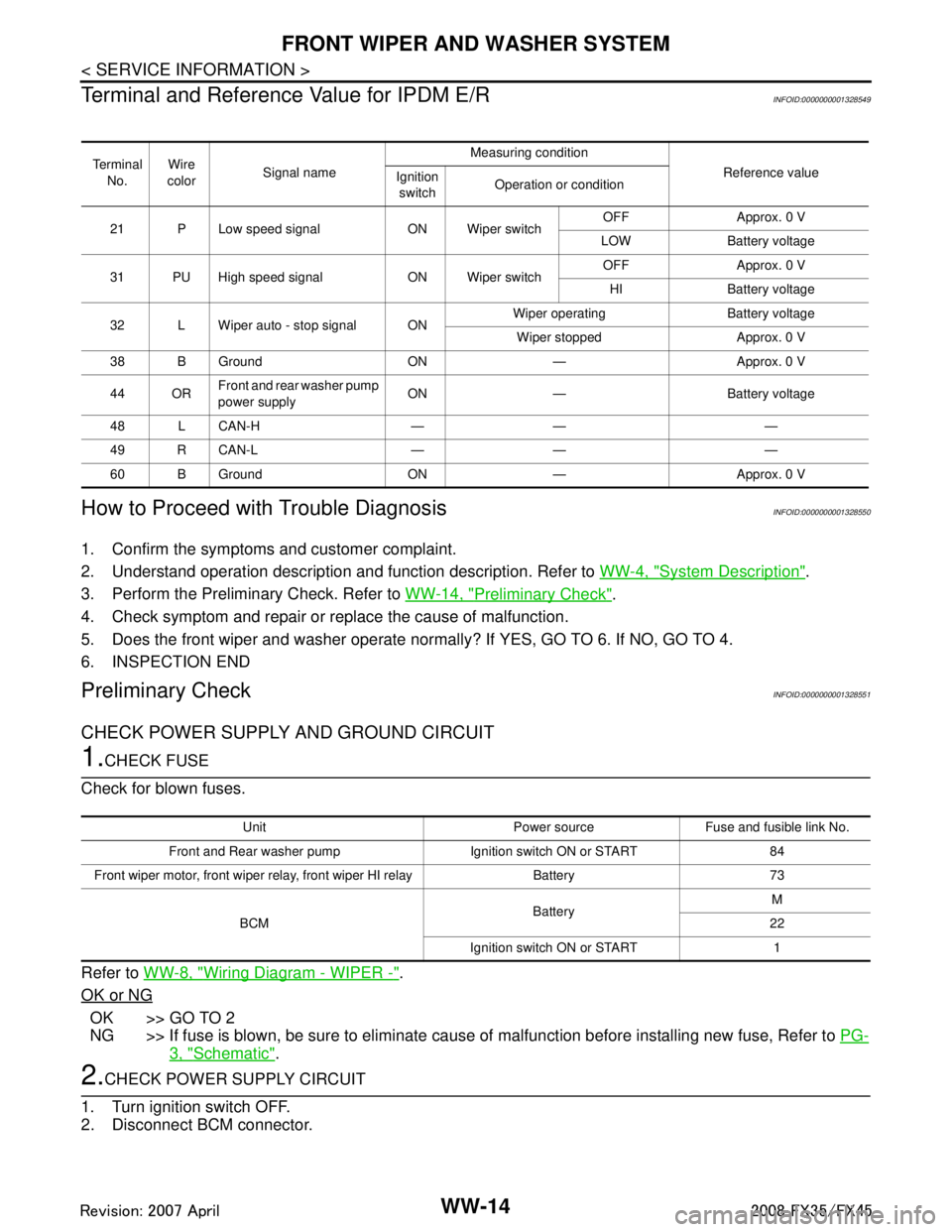
Terminal and Reference Value for IPDM E/R
INFOID:0000000001328549
How to Proceed with Trouble DiagnosisINFOID:0000000001328550
1. Confirm the symptoms and customer complaint.
2. Understand operation description and function description. Refer to WW-4, "
System Description".
3. Perform the Preliminary Check. Refer to WW-14, "
Preliminary Check".
4. Check symptom and repair or r eplace the cause of malfunction.
5. Does the front wiper and washer operate norma lly? If YES, GO TO 6. If NO, GO TO 4.
6. INSPECTION END
Preliminary CheckINFOID:0000000001328551
CHECK POWER SUPPLY AND GROUND CIRCUIT
1.CHECK FUSE
Check for blown fuses.
Refer to WW-8, "
Wiring Diagram - WIPER -".
OK or NG
OK >> GO TO 2
NG >> If fuse is blown, be sure to eliminate caus e of malfunction before installing new fuse, Refer to PG-
3, "Schematic".
2.CHECK POWER SUPPLY CIRCUIT
1. Turn ignition switch OFF.
2. Disconnect BCM connector.
Te r m i n a l No. Wire
color Signal name Measuring condition
Reference value
Ignition
switch Operation or condition
21 P Low speed signal ON Wiper switch OFF Approx. 0 V
LOW Battery voltage
31 PU High speed signal ON Wiper switch OFF Approx. 0 V
HI Battery voltage
32 L Wiper auto - stop signal ON Wiper operating Battery voltage
Wiper stopped Approx. 0 V
38 B Ground ON — Approx. 0 V
44 OR Front and rear washer pump
power supply ON — Battery voltage
48 L CAN-H — — —
49 R CAN-L — — —
60 B Ground ON — Approx. 0 V
Unit Power source Fuse and fusible link No.
Front and Rear washer pump Ignition switch ON or START 84
Front wiper motor, front wiper rela y, front wiper HI relay Battery 73
BCM BatteryM
22
Ignition switch ON or START 1
3AA93ABC3ACD3AC03ACA3AC03AC63AC53A913A773A893A873A873A8E3A773A983AC73AC93AC03AC3
3A893A873A873A8F3A773A9D3AAF3A8A3A8C3A863A9D3AAF3A8B3A8C
Page 3894 of 3924

FRONT WIPER AND WASHER SYSTEMWW-19
< SERVICE INFORMATION >
C
DE
F
G H
I
J
L
M A
B
WW
N
O P
OK or NG
OK >> Replace IPDM E/R.
NG >> GO TO 2.
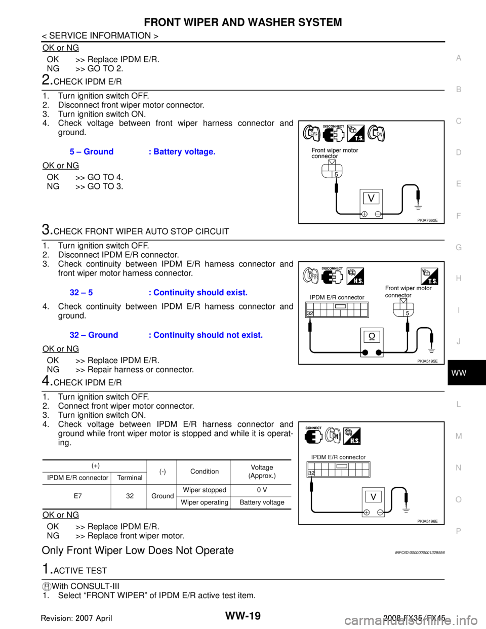
2.CHECK IPDM E/R
1. Turn ignition switch OFF.
2. Disconnect front wiper motor connector.
3. Turn ignition switch ON.
4. Check voltage between front wiper harness connector and ground.
OK or NG
OK >> GO TO 4.
NG >> GO TO 3.
3.CHECK FRONT WIPER AUTO STOP CIRCUIT
1. Turn ignition switch OFF.
2. Disconnect IPDM E/R connector.
3. Check continuity between IPDM E/R harness connector and front wiper motor harness connector.
4. Check continuity between IPDM E/R harness connector and ground.
OK or NG
OK >> Replace IPDM E/R.
NG >> Repair harness or connector.
4.CHECK IPDM E/R
1. Turn ignition switch OFF.
2. Connect front wiper motor connector.
3. Turn ignition switch ON.
4. Check voltage between IPDM E/R harness connector and ground while front wiper motor is stopped and while it is operat-
ing.
OK or NG
OK >> Replace IPDM E/R.
NG >> Replace front wiper motor.
Only Front Wiper Low Does Not OperateINFOID:0000000001328556
1.ACTIVE TEST
With CONSULT-III
1. Select “FRONT WIPER” of IPDM E/R active test item.
5 – Ground : Battery voltage.
PKIA7662E
32 – 5 : Continuity should exist.
32 – Ground : Continuity should not exist.
PKIA5195E
(+)
(-) Condition Voltag e
(Approx.)
IPDM E/R connector Terminal
E7 32 Ground Wiper stopped 0 V
Wiper operating Battery voltage
PKIA5196E
3AA93ABC3ACD3AC03ACA3AC03AC63AC53A913A773A893A873A873A8E3A773A983AC73AC93AC03AC3
3A893A873A873A8F3A773A9D3AAF3A8A3A8C3A863A9D3AAF3A8B3A8C
Page 3898 of 3924

FRONT WIPER AND WASHER SYSTEMWW-23
< SERVICE INFORMATION >
C
DE
F
G H
I
J
L
M A
B
WW
N
O P
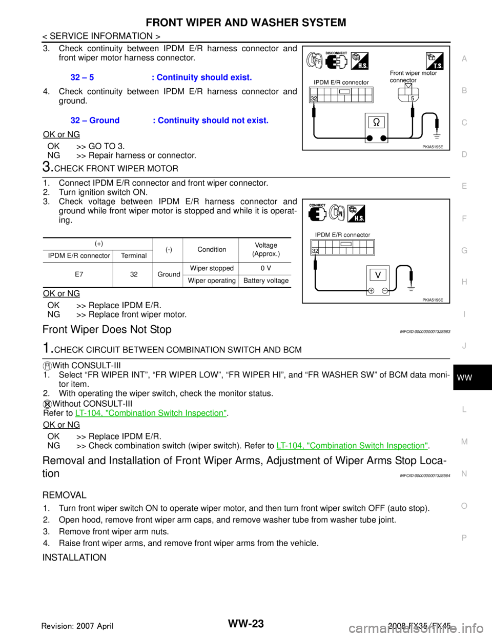
3. Check continuity between IPDM E/R harness connector and front wiper motor harness connector.
4. Check continuity between IPDM E/R harness connector and ground.
OK or NG
OK >> GO TO 3.
NG >> Repair harness or connector.
3.CHECK FRONT WIPER MOTOR
1. Connect IPDM E/R connector and front wiper connector.
2. Turn ignition switch ON.
3. Check voltage between IPDM E/R harness connector and ground while front wiper motor is stopped and while it is operat-
ing.
OK or NG
OK >> Replace IPDM E/R.
NG >> Replace front wiper motor.
Front Wiper Does Not StopINFOID:0000000001328563
1.CHECK CIRCUIT BETWEEN COMB INATION SWITCH AND BCM
With CONSULT-III
1. Select “FR WIPER INT”, “FR WI PER LOW”, “FR WIPER HI”, and “FR WASHER SW” of BCM data moni-
tor item.
2. With operating the wiper switch, check the monitor status.
Without CONSULT-III
Refer to LT-104, "
Combination Switch Inspection".
OK or NG
OK >> Replace IPDM E/R.
NG >> Check combination switch (wiper switch). Refer to LT-104, "
Combination Switch Inspection".
Removal and Installation of Front Wiper Arms, Adjustment of Wiper Arms Stop Loca-
tion
INFOID:0000000001328564
REMOVAL
1. Turn front wiper switch ON to operate wiper moto r, and then turn front wiper switch OFF (auto stop).
2. Open hood, remove front wiper arm caps, and remove washer tube from washer tube joint.
3. Remove front wiper arm nuts.
4. Raise front wiper arms, and remove front wiper arms from the vehicle.
INSTALLATION
32 – 5 : Continuity should exist.
32 – Ground : Continuity should not exist.
PKIA5195E
(+) (-) Condition Vo l ta g e
(Approx.)
IPDM E/R connector Terminal
E7 32 Ground Wiper stopped 0 V
Wiper operating Battery voltage
PKIA5196E
3AA93ABC3ACD3AC03ACA3AC03AC63AC53A913A773A893A873A873A8E3A773A983AC73AC93AC03AC3
3A893A873A873A8F3A773A9D3AAF3A8A3A8C3A863A9D3AAF3A8B3A8C
Page 3914 of 3924

REAR WIPER AND WASHER SYSTEMWW-39
< SERVICE INFORMATION >
C
DE
F
G H
I
J
L
M A
B
WW
N
O P
Rear Wiper Does Not Re turn to Stop PositionINFOID:0000000001328584
1.CHECK REAR WIPER MOTOR CIRCUIT
With CONSULT-III
1. Select “RR WIPER STOP” of BCM data monitor item.
2. Check that “RR WIPER STOP”, turn ON-O FF linked with rear wiper switch operation.
Without CONSULT-III
GO TO 2.
OK or NG
OK >> Replace BCM. Refer to BCS-13, "Removal and Installation of BCM".
NG >> GO TO 2.
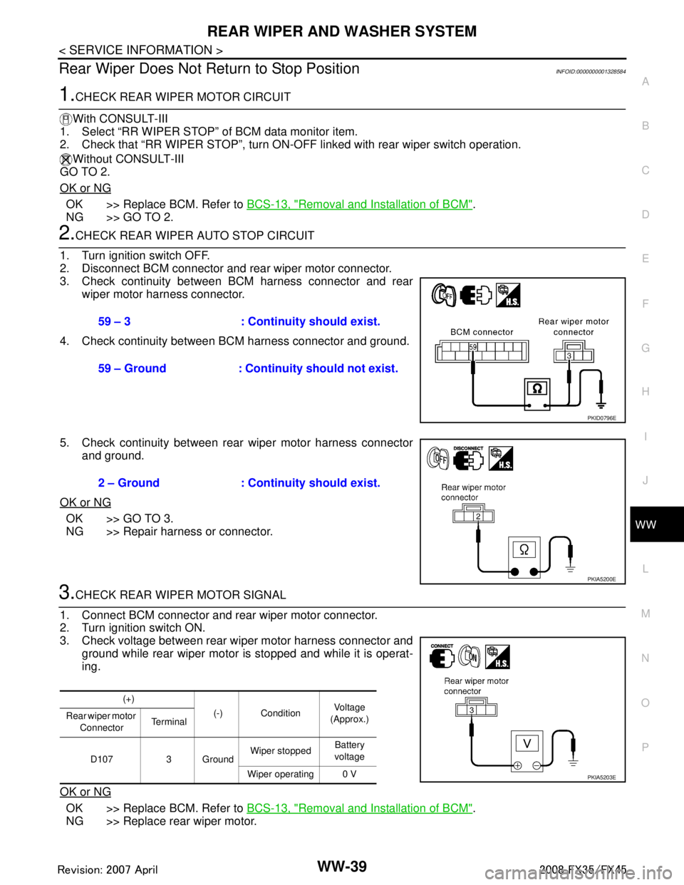
2.CHECK REAR WIPER AUTO STOP CIRCUIT
1. Turn ignition switch OFF.
2. Disconnect BCM connector and rear wiper motor connector.
3. Check continuity between BCM harness connector and rear wiper motor harness connector.
4. Check continuity between BCM harness connector and ground.
5. Check continuity between rear wiper motor harness connector and ground.
OK or NG
OK >> GO TO 3.
NG >> Repair harness or connector.
3.CHECK REAR WIPER MOTOR SIGNAL
1. Connect BCM connector and rear wiper motor connector.
2. Turn ignition switch ON.
3. Check voltage between rear wiper motor harness connector and ground while rear wiper motor is stopped and while it is operat-
ing.
OK or NG
OK >> Replace BCM. Refer to BCS-13, "Removal and Installation of BCM".
NG >> Replace rear wiper motor.
59 – 3 : Continuity should exist.
59 – Ground : Continuity should not exist.
PKID0796E
2 – Ground : Continuity should exist.
PKIA5200E
(+)
(-) Condition Vo l ta g e
(Approx.)
Rear wiper motor
Connector Te r m i n a l
D107 3 Ground Wiper stopped
Battery
voltage
Wiper operating 0 V
PKIA5203E
3AA93ABC3ACD3AC03ACA3AC03AC63AC53A913A773A893A873A873A8E3A773A983AC73AC93AC03AC3
3A893A873A873A8F3A773A9D3AAF3A8A3A8C3A863A9D3AAF3A8B3A8C