2008 INFINITI FX35 air condition
[x] Cancel search: air conditionPage 3715 of 3924
SE-76
< SERVICE INFORMATION >
AUTOMATIC DRIVE POSITIONER
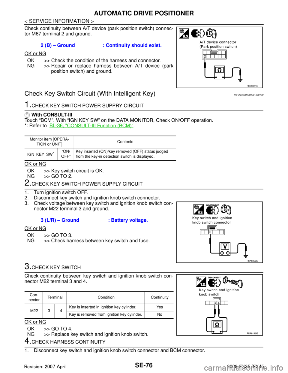
Check continuity between A/T device (park position switch) connec-
tor M67 terminal 2 and ground.
OK or NG
OK >> Check the condition of the harness and connector.
NG >> Repair or replace harness between A/T device (park position switch) and ground.
Check Key Switch Circuit (With Intelligent Key)INFOID:0000000001328139
1.CHECK KEY SWITCH POWER SUPPRY CIRCUIT
With CONSULT-III
Touch “BCM”. With “IGN KEY SW” on the DATA MONITOR, Check ON/OFF operation.
*: Refer to BL-36, "
CONSULT-III Function (BCM)".
OK or NG
OK >> Key switch circuit is OK.
NG >> GO TO 2.
2.CHECK KEY SWITCH PO WER SUPPLY CIRCUIT
1. Turn ignition switch OFF.
2. Disconnect key switch and ignition knob switch connector.
3. Check voltage between key switch and ignition knob switch con- nector M22 terminal 3 and ground.
OK or NG
OK >> GO TO 3.
NG >> Check harness between key switch and fuse.
3.CHECK KEY SWITCH
Check continuity between key switch and ignition knob switch con-
nector M22 terminal 3 and 4.
OK or NG
OK >> GO TO 4.
NG >> Replace key switch and ignition knob switch.
4.CHECK HARNESS CONTINUITY
1. Disconnect key switch and ignition knob switch connector and BCM connector. 2 (B) – Ground : Continuity should exist.
PIIB9071E
Monitor item [OPERA-
TION or UNIT] Contents
IGN KEY SW
*“ON/
OFF” Key inserted (ON)/key removed (OFF) status judged
from the key-in detection switch is displayed.
3 (L/R) – Ground : Battery voltage.
PIIA5093E
Con-
nector Terminal Condition Continuity
M22 3 4 Key is inserted in ignition key cylinder. Yes
Key is removed from ignition key cylinder. No
PIIA6140E
3AA93ABC3ACD3AC03ACA3AC03AC63AC53A913A773A893A873A873A8E3A773A983AC73AC93AC03AC3
3A893A873A873A8F3A773A9D3AAF3A8A3A8C3A863A9D3AAF3A8B3A8C
Page 3716 of 3924
AUTOMATIC DRIVE POSITIONERSE-77
< SERVICE INFORMATION >
C
DE
F
G H
J
K L
M A
B
SE
N
O P
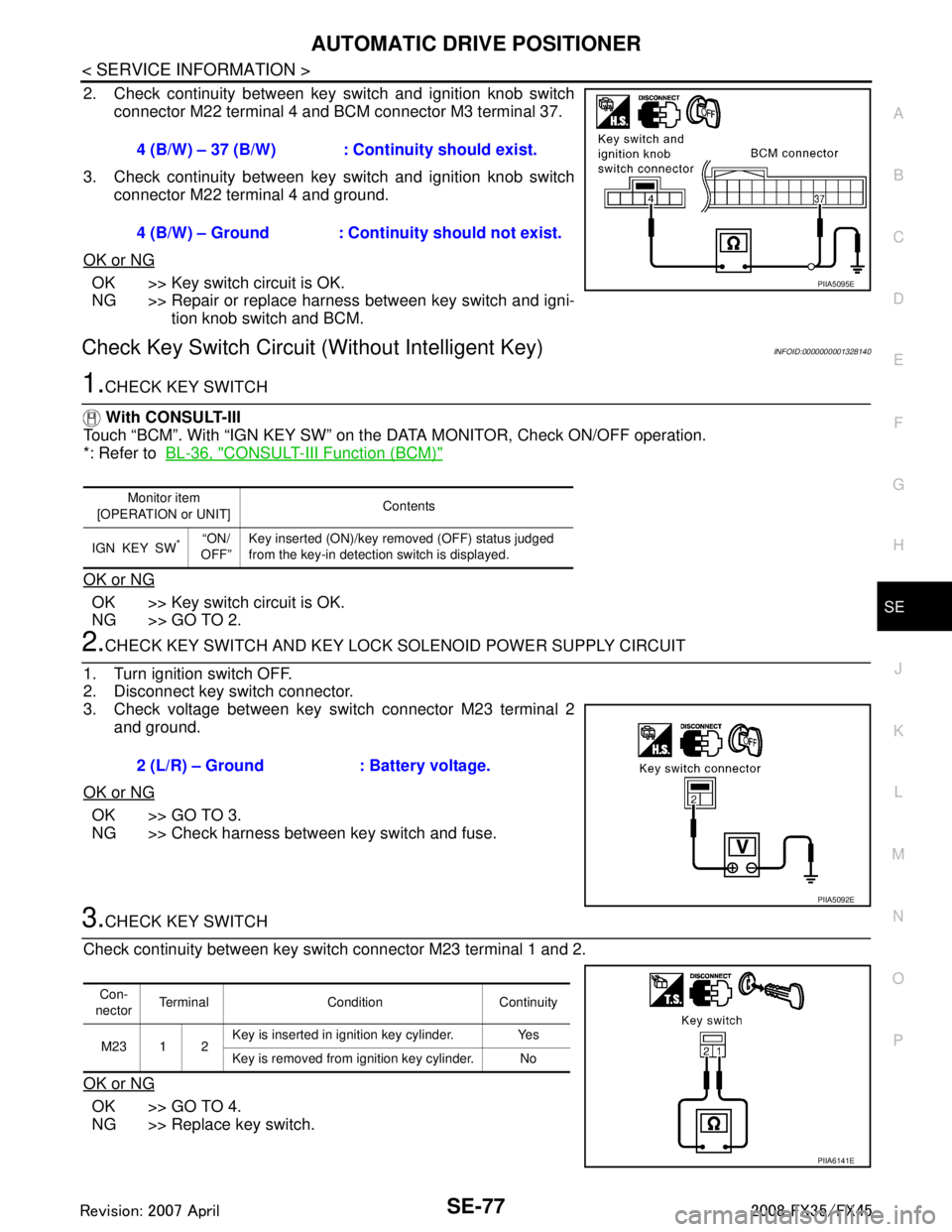
2. Check continuity between key switch and ignition knob switch connector M22 terminal 4 and BCM connector M3 terminal 37.
3. Check continuity between key switch and ignition knob switch connector M22 terminal 4 and ground.
OK or NG
OK >> Key switch circuit is OK.
NG >> Repair or replace harness between key switch and igni- tion knob switch and BCM.
Check Key Switch Circui t (Without Intelligent Key)INFOID:0000000001328140
1.CHECK KEY SWITCH
With CONSULT-III
Touch “BCM”. With “IGN KEY SW” on the DATA MONITOR, Check ON/OFF operation.
*: Refer to BL-36, "
CONSULT-III Function (BCM)"
OK or NG
OK >> Key switch circuit is OK.
NG >> GO TO 2.
2.CHECK KEY SWITCH AND KEY LOCK SOLENOID POWER SUPPLY CIRCUIT
1. Turn ignition switch OFF.
2. Disconnect key switch connector.
3. Check voltage between key switch connector M23 terminal 2 and ground.
OK or NG
OK >> GO TO 3.
NG >> Check harness between key switch and fuse.
3.CHECK KEY SWITCH
Check continuity between key switch connector M23 terminal 1 and 2.
OK or NG
OK >> GO TO 4.
NG >> Replace key switch. 4 (B/W) – 37 (B/W) : Cont
inuity should exist.
4 (B/W) – Ground : Continuity should not exist.
PIIA5095E
Monitor item
[OPERATION or UNIT] Contents
IGN KEY SW
*“ON/
OFF” Key inserted (ON)/key removed (OFF) status judged
from the key-in detection switch is displayed.
2 (L/R) – Ground : Battery voltage.
PIIA5092E
Con-
nector Terminal Condition Continuity
M23 1 2 Key is inserted in ignition key cylinder. Yes
Key is removed from ignition key cylinder. No
PIIA6141E
3AA93ABC3ACD3AC03ACA3AC03AC63AC53A913A773A893A873A873A8E3A773A983AC73AC93AC03AC3
3A893A873A873A8F3A773A9D3AAF3A8A3A8C3A863A9D3AAF3A8B3A8C
Page 3717 of 3924
SE-78
< SERVICE INFORMATION >
AUTOMATIC DRIVE POSITIONER
4.CHECK HARNESS CONTINUITY
1. Disconnect key switch connector and BCM connector.
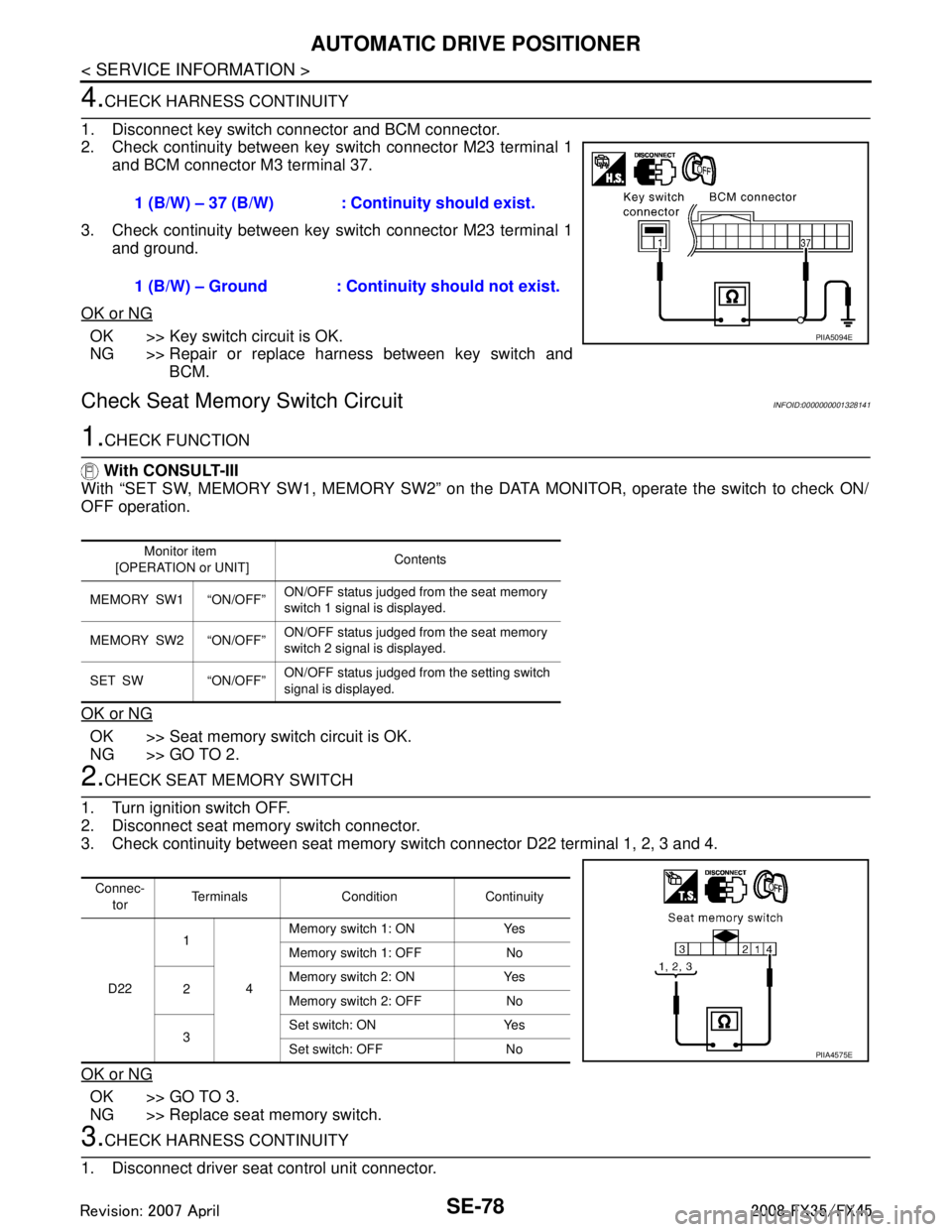
2. Check continuity between key switch connector M23 terminal 1 and BCM connector M3 terminal 37.
3. Check continuity between key switch connector M23 terminal 1 and ground.
OK or NG
OK >> Key switch circuit is OK.
NG >> Repair or replace harness between key switch and BCM.
Check Seat Memory Switch CircuitINFOID:0000000001328141
1.CHECK FUNCTION
With CONSULT-III
With “SET SW, MEMORY SW1, MEMO RY SW2” on the DATA MONITOR, operate the switch to check ON/
OFF operation.
OK or NG
OK >> Seat memory switch circuit is OK.
NG >> GO TO 2.
2.CHECK SEAT MEMORY SWITCH
1. Turn ignition switch OFF.
2. Disconnect seat memory switch connector.
3. Check continuity between seat memory s witch connector D22 terminal 1, 2, 3 and 4.
OK or NG
OK >> GO TO 3.
NG >> Replace seat memory switch.
3.CHECK HARNESS CONTINUITY
1. Disconnect driver seat control unit connector. 1 (B/W) – 37 (B/W) : Cont
inuity should exist.
1 (B/W) – Ground : Conti nuity should not exist.
PIIA5094E
Monitor item
[OPERATION or UNIT] Contents
MEMORY SW1 “ON/OFF” ON/OFF status judged from the seat memory
switch 1 signal is displayed.
MEMORY SW2 “ON/OFF” ON/OFF status judged from the seat memory
switch 2 signal is displayed.
SET SW “ON/OFF” ON/OFF status judged from the setting switch
signal is displayed.
Connec-
tor Terminals Condition Continuity
D22 1
4Memory switch 1: ON Yes
Memory switch 1: OFF No
2 Memory switch 2: ON Yes
Memory switch 2: OFF No
3 Set switch: ON Yes
Set switch: OFF No
PIIA4575E
3AA93ABC3ACD3AC03ACA3AC03AC63AC53A913A773A893A873A873A8E3A773A983AC73AC93AC03AC3
3A893A873A873A8F3A773A9D3AAF3A8A3A8C3A863A9D3AAF3A8B3A8C
Page 3720 of 3924
AUTOMATIC DRIVE POSITIONERSE-81
< SERVICE INFORMATION >
C
DE
F
G H
J
K L
M A
B
SE
N
O P
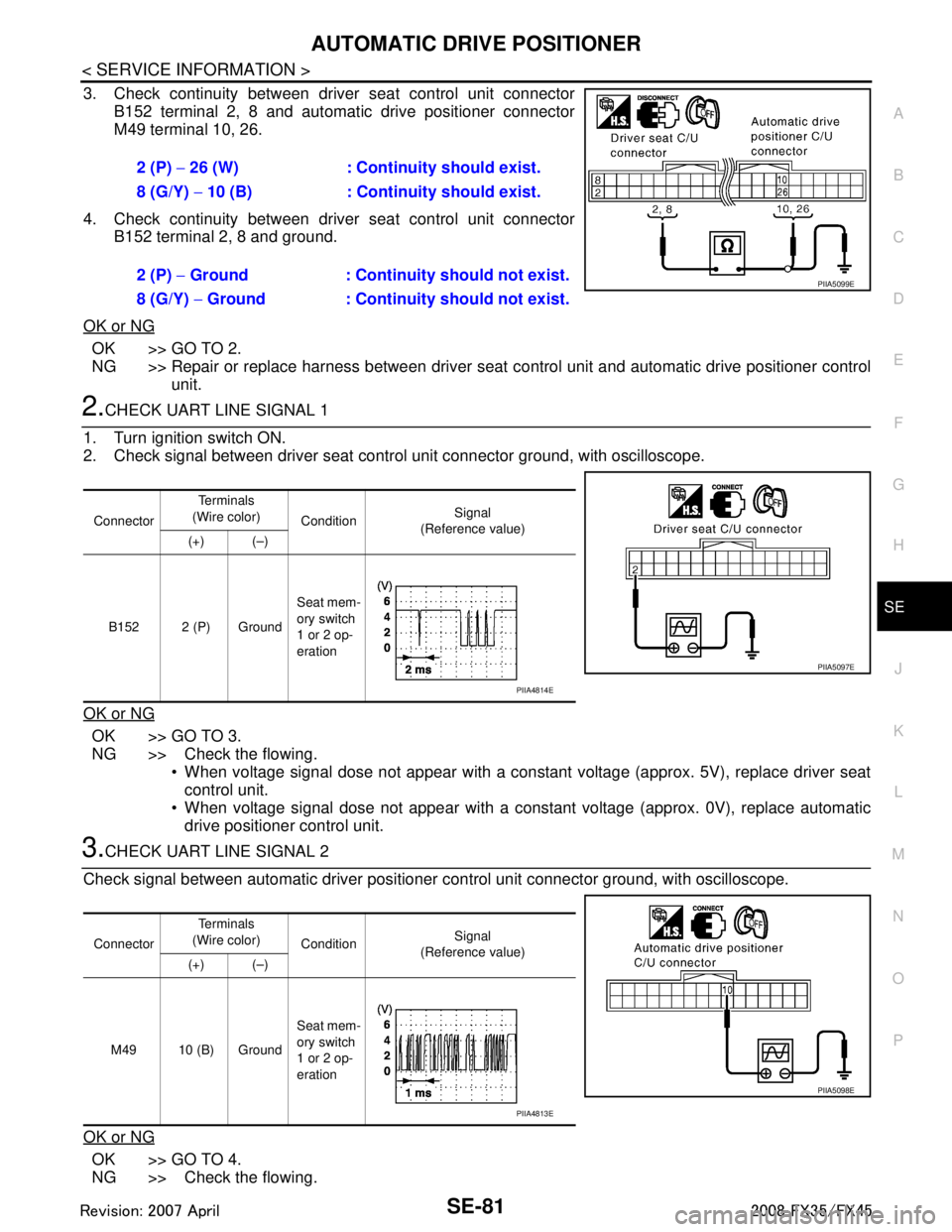
3. Check continuity between driver seat control unit connector B152 terminal 2, 8 and automatic drive positioner connector
M49 terminal 10, 26.
4. Check continuity between driver seat control unit connector B152 terminal 2, 8 and ground.
OK or NG
OK >> GO TO 2.
NG >> Repair or replace harness between driver seat control unit and automatic drive positioner control
unit.
2.CHECK UART LINE SIGNAL 1
1. Turn ignition switch ON.
2. Check signal between driver seat contro l unit connector ground, with oscilloscope.
OK or NG
OK >> GO TO 3.
NG >> Check the flowing. When voltage signal dose not appear with a constant voltage (approx. 5V), replace driver seat
control unit.
When voltage signal dose not appear with a const ant voltage (approx. 0V), replace automatic
drive positioner control unit.
3.CHECK UART LINE SIGNAL 2
Check signal between automatic driver positioner control unit connector ground, with oscilloscope.
OK or NG
OK >> GO TO 4.
NG >> Check the flowing. 2 (P)
− 26 (W) : Continuity should exist.
8 (G/Y) − 10 (B) : Continui ty should exist.
2 (P) − Ground : Continuity should not exist.
8 (G/Y) − Ground : Continuity should not exist.
PIIA5099E
Connector Te r m i n a l s
(Wire color) Condition Signal
(Reference value)
(+) (–)
B152 2 (P) Ground Seat mem-
ory switch
1 or 2 op-
eration
PIIA5097E
PIIA4814E
Connector
Te r m i n a l s
(Wire color) Condition Signal
(Reference value)
(+) (–)
M49 10 (B) Ground Seat mem-
ory switch
1 or 2 op-
eration
PIIA5098E
PIIA4813E
3AA93ABC3ACD3AC03ACA3AC03AC63AC53A913A773A893A873A873A8E3A773A983AC73AC93AC03AC3
3A893A873A873A8F3A773A9D3AAF3A8A3A8C3A863A9D3AAF3A8B3A8C
Page 3721 of 3924
SE-82
< SERVICE INFORMATION >
AUTOMATIC DRIVE POSITIONER
When voltage signal dose not appear with a constant voltage (approx. 5V), replace automatic
driver seat control unit.
When voltage signal dose not appear with a constant voltage (approx. 0V), replace driver seat
control unit.
4.CHECK DRIVER SEAT CONTROL UNIT
Dose the automatic drive positioner operate, when the driver seat control unit exchanged?
Does seat memory function operate?
YES >> Replace automatic drive positioner control unit.
NG >> Replace driver seat control unit.
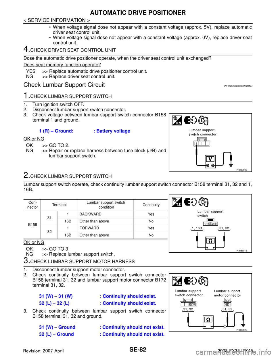
Check Lumbar Support CircuitINFOID:0000000001328144
1.CHECK LUMBAR SUPPORT SWITCH
1. Turn ignition switch OFF.
2. Disconnect lumbar support switch connector.
3. Check voltage between lumbar support switch connector B158 terminal 1 and ground.
OK or NG
OK >> GO TO 2.
NG >> Repair or replace harness between fuse block (J/B) and lumbar support switch.
2.CHECK LUMBAR SUPPORT SWITCH
Lumbar support switch operate, check continuity lum bar support switch connector B158 terminal 31, 32 and 1,
16B.
OK or NG
OK >> GO TO 3.
NG >> Replace lumbar support switch.
3.CHECK LUMBAR SUPPORT MOTOR HARNESS
1. Disconnect lumbar support motor connector.
2. Check continuity between lumbar support switch connector B158 terminal 31, 32 and lumbar support motor connector B172
terminal 31, 32.
3. Check continuity between lumbar support switch connector B158 terminal 31, 32 and ground.1 (R) – Ground: : Battery voltage
PIIB8600E
Con-
nector Te r m i n a l
Lumbar support switch
condition Continuity
B158 31
1 BACKWARD Yes
16B Other than above No
32 1FORWARD Yes
16B Other than above No
PIIB8601E
31 (W) − 31 (W) : Continuity should exist.
32 (L) − 32 (L) : Continuity should exist.
31 (W) − Ground : Continuity should not exist.
32 (L) − Ground : Continuity should not exist.
PIIB8602E
3AA93ABC3ACD3AC03ACA3AC03AC63AC53A913A773A893A873A873A8E3A773A983AC73AC93AC03AC3
3A893A873A873A8F3A773A9D3AAF3A8A3A8C3A863A9D3AAF3A8B3A8C
Page 3722 of 3924
AUTOMATIC DRIVE POSITIONERSE-83
< SERVICE INFORMATION >
C
DE
F
G H
J
K L
M A
B
SE
N
O P
OK or NG
OK >> GO TO 4.
NG >> Repair or replace harness between lumbar support switch and lumbar support motor.
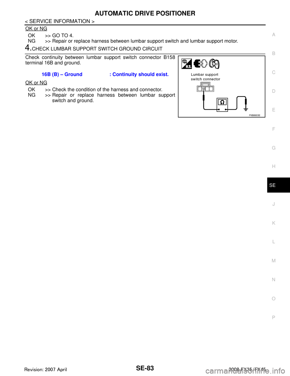
4.CHECK LUMBAR SUPPORT SWITCH GROUND CIRCUIT
Check continuity between lumbar support switch connector B158
terminal 16B and ground.
OK or NG
OK >> Check the condition of the harness and connector.
NG >> Repair or replace harness between lumbar support switch and ground.
16B (B) – Ground : Continuity should exist.
PIIB8603E
3AA93ABC3ACD3AC03ACA3AC03AC63AC53A913A773A893A873A873A8E3A773A983AC73AC93AC03AC3
3A893A873A873A8F3A773A9D3AAF3A8A3A8C3A863A9D3AAF3A8B3A8C
Page 3738 of 3924

SRS-1
RESTRAINTS
C
DE
F
G
I
J
K L
M
SECTION SRS
A
B
SRS
N
O P
CONTENTS
SUPPLEMENTAL RESTRAINT SYSTEM (SRS)
SERVICE INFORMATION .. ..........................2
DTC INDEX ..................................................... .....2
B1001-B1015 ...................................................... ......2
B1017-B1035 ............................................................2
B1042-B1057 ............................................................3
B1058-B1073 ............................................................3
B1074-B1089 ............................................................4
B1106-B1120 ............................................................4
B1122-B1137 ............................................................5
B1138-B1153 ............................................................5
B1202-B1210 ............................................................5
PRECAUTIONS ...................................................7
Precaution for Supplemental Restraint System
(SRS) "AIR BAG" and "SEAT BELT PRE-TEN-
SIONER" ............................................................. ......
7
Precaution for SRS "AIR BAG" and "SEAT BELT
PRE-TENSIONER" Service ......................................
7
Occupant Classification System Precaution .............7
PREPARATION ...................................................8
Commercial Service Tool .................................... ......8
SUPPLEMENTAL RESTRAINT SYSTEM
(SRS) ...................................................................
9
SRS Configuration .............................................. ......9
Front Seat Belt Pre-tensioner with Load Limiter .....10
Front Side Air Bag ...................................................10
Side Curtain Air Bag ................................................10
Occupant Classification System (OCS) ..................10
Passenger Air Bag Status Condition .......................11
Component Parts of Occupant Classification Sys-
tem ..........................................................................
11
TROUBLE DIAGNOSIS .....................................12
Trouble Diagnosis Introduction ........................... ....12
Component Parts Location ......................................14
Schematic ...............................................................15
Wiring Diagram - SRS - ...........................................16
CONSULT-III Function ........................................
....21
Self-Diagnosis Function (Without CONSULT-III) .....22
SRS Operation Check .............................................23
Trouble Diagnosis with CONSULT-III ......................24
Trouble Diagnosis without CONSULT-III .................28
Trouble Diagnosis: "AIR BAG" Warning Lamp
Does Not Turn OFF .................................................
32
Trouble Diagnosis: "AIR BAG" Warning Lamp
Does Not Turn ON ...................................................
32
DRIVER AIR BAG MODULE ............................34
Removal and Installation .........................................34
SPIRAL CABLE ................................................36
Removal and Installation .........................................36
FRONT PASSENGER AIR BAG MODULE ......38
Removal and Installation .........................................38
SIDE CURTAIN AIR BAG MODULE ................40
Removal and Installation .........................................40
CRASH ZONE SENSOR ...................................42
Removal and Installation ..................................... ....42
SIDE AIR BAG (SATELLITE) SENSOR ...........43
Removal and Installation .........................................43
DIAGNOSIS SENSOR UNIT .............................44
Removal and Installation .........................................44
FRONT SEAT BELT PRE-TENSIONER ...........45
Removal and Installation .........................................45
OCCUPANT CLASSIFICATION SYSTEM
CONTROL UNIT ................................................
46
Removal and Installation .........................................46
COLLISION DIAGNOSIS ..................................47
For Frontal Collision ................................................47
For Side Collision ....................................................48
3AA93ABC3ACD3AC03ACA3AC03AC63AC53A913A773A893A873A873A8E3A773A983AC73AC93AC03AC3
3A893A873A873A8F3A773A9D3AAF3A8A3A8C3A863A9D3AAF3A8B3A8C
Page 3748 of 3924
SUPPLEMENTAL RESTRAINT SYSTEM (SRS)SRS-11
< SERVICE INFORMATION >
C
DE
F
G
I
J
K L
M A
B
SRS
N
O P
Passenger Air Bag Status ConditionINFOID:0000000001524159
NOTE:
Passenger does not meet Ocuupant classification System specifications for passenger air bag activation.
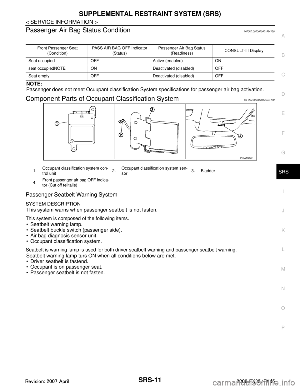
Component Parts of Occupant Classification SystemINFOID:0000000001524160
Passenger Seatbelt Warning System
SYSTEM DESCRIPTION
This system warns when passenger seatbelt is not fasten.
This system is composed of the following items.
Seatbelt warning lamp.
Seatbelt buckle switch (passenger side).
Air bag diagnosis sensor unit.
Occupant classification system.
Seatbelt is warning lamp is used for both driver seatbelt warning and passenger seatbelt warning.
Seatbelt warning lamp turs ON when all conditions below are met.
Driver seatbelt is fastend.
Occupant is on passenger seat.
Passenger seatbelt is not fasten.
Front Passenger Seat
(Condition) PASS AIR BAG OFF Indicator
(Status) Passenger Air Bag Status
(Readiness) CONSULT-III Display
Seat occupied OFF Active (enabled) ON
seat occupiedNOTE ON Deactivated (disabled) OFF
Seat empty OFF Deactivated (disabled) OFF
PHIA1334E
1. Occupant classification system con-
trol unit 2.Occupant classification system sen-
sor 3. Bladder
4. Front passenger air bag OFF indica-
tor (Cut off telltaile)
3AA93ABC3ACD3AC03ACA3AC03AC63AC53A913A773A893A873A873A8E3A773A983AC73AC93AC03AC3
3A893A873A873A8F3A773A9D3AAF3A8A3A8C3A863A9D3AAF3A8B3A8C