2008 INFINITI FX35 battery
[x] Cancel search: batteryPage 1155 of 3924

UNIFIED METER AND A/C AMPDI-29
< SERVICE INFORMATION >
C
DE
F
G H
I
J
L
M A
B
DI
N
O P
NOTE:
Monitored item that does not match the vehicle is deleted from the display automatically.
*1: It dose not change when fastening or unfastening the passenger seat belt.
*2: Monitor keeps indicating “off” when brake warning lamp is on by the parking brake operation or low brake fluid level.
Power Supply and Gro und Circuit InspectionINFOID:0000000001328459
1.CHECK FUSE
Check for blown unified meter and A/C amp. fuses.
OK or NG
OK >> GO TO 2.
NG >> Be sure to eliminate cause of malfunction before installing new fuse. Refer to PG-3, "
Schematic".
2.CHECK POWER SUPPLY CIRCUIT
OIL W/L [On/Off] X Indicates [On/Off] condition of oil pressure warning lamp.
VDC/TCS IND [On/Off] X Indicates [On/Off] condition of VDC OFF indicator lamp.
ABS W/L [On/Off] X Indicates [On/Off] condition of ABS warning lamp.
SLIP IND [On/Off] X Indicates [On/Off] condition of SLIP indicator lamp.
BRAKE W/L [On/Off]
*2X Indicates [On/Off] condition of brake warning lamp.
KEY G W/L [On/Off] X Indicates [On/Off] condition of key warning lamp (green).
KEY R W/L [On/Off] X Indicates [On/Off] condition of key warning lamp (red).
KEY KNOB W/L [On/Off] X Indicates [On/Off] condition of key knob warning lamp.
M RANGE SW [On/Off] X X Indicates [On/Off] condition of manual mode range switch.
NM RANGE SW [On/Off] X X Indicates [On/Off] condition of except for manual mode range
switch.
AT SFT UP SW [On/Off] X X Indicates [On/Off] condition of A/T shift-up switch.
AT SFT DWN SW [On/Off] X X Indicates [On/Off] condition of A/T shift-down switch.
BRAKE SW [On/Off] X Indicates [On/Off] condition of brake switch (stop lamp switch).
AT-M IND [On/Off] X X Indicates [On/Off] condition of A/T manual mode indicator.
AT-M GEAR [5-1] X X Indicates [5-1] condition of A/T manual mode gear position.
P RANGE IND [On/Off] X X Indicates [On/Off] condition of A/T shift P range indicator.
R RANGE IND [On/Off] X X Indicates [On/Off] condition of A/T shift R range indicator.
N RANGE IND [On/Off] X X Indicates [On/Off] condition of A/T shift N range indicator.
D RANGE IND [On/Off] X X Indicates [On/Off] condition of A/T shift D range indicator.
AT CHECK W/L X Indicates [On/Off] cond ition of AT CHECK warning lamp.
CRUISE IND [On/Off] X Indicates [On/Off] condition of CRUISE indicator lamp.
SET IND [On/Off] X Indicates [On/Off] condition of SET indicator lamp.
CRUISE W/L [On/Off] X Indicates [On/Of f] condition of ICC warning lamp.
4WD LOCK SW [On/Off] X This item is not used for this model. “off” is always displayed.
4WD LOCK IND [On/Off] X This item is not used for this model. “off” is always displayed.
4WD W/L [On/Off] X Indicates [On/Off] condition of AWD warning lamp.
RR COMB STATE [OK/NG] X Indicates [OK/NG] condition of rear combination lamp circuit. Display item [Unit]
MAIN
SIGNALS SELECTION
FROM MENU Contents
Power source Fuse No.
Battery power supply 19 ACC power supply 10, 11
Ignition power supply 12
3AA93ABC3ACD3AC03ACA3AC03AC63AC53A913A773A893A873A873A8E3A773A983AC73AC93AC03AC3
3A893A873A873A8F3A773A9D3AAF3A8A3A8C3A863A9D3AAF3A8B3A8C
Page 1156 of 3924
DI-30
< SERVICE INFORMATION >
UNIFIED METER AND A/C AMP
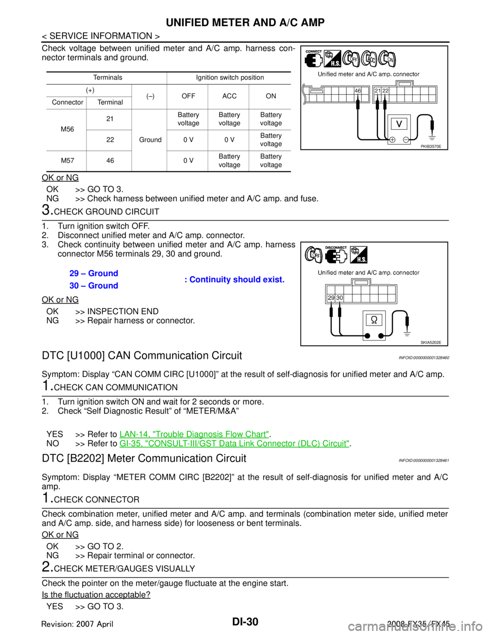
Check voltage between unified meter and A/C amp. harness con-
nector terminals and ground.
OK or NG
OK >> GO TO 3.
NG >> Check harness between unified meter and A/C amp. and fuse.
3.CHECK GROUND CIRCUIT
1. Turn ignition switch OFF.
2. Disconnect unified meter and A/C amp. connector.
3. Check continuity between unified meter and A/C amp. harness connector M56 terminals 29, 30 and ground.
OK or NG
OK >> INSPECTION END
NG >> Repair harness or connector.
DTC [U1000] CAN Communication CircuitINFOID:0000000001328460
Symptom: Display “CAN COMM CIRC [U1000]” at the re sult of self-diagnosis for unified meter and A/C amp.
1.CHECK CAN COMMUNICATION
1. Turn ignition switch ON and wait for 2 seconds or more.
2. Check “Self Diagnostic Result” of “METER/M&A”
YES >> Refer to LAN-14, "
Trouble Diagnosis Flow Chart".
NO >> Refer to GI-35, "
CONSULT-III/GST Data Link Connector (DLC) Circuit".
DTC [B2202] Meter Communication CircuitINFOID:0000000001328461
Symptom: Display “METER COMM CI RC [B2202]” at the result of self-diagnosis for unified meter and A/C
amp.
1.CHECK CONNECTOR
Check combination meter, unified meter and A/C amp. and terminals (combination meter side, unified meter
and A/C amp. side, and harness side) for looseness or bent terminals.
OK or NG
OK >> GO TO 2.
NG >> Repair terminal or connector.
2.CHECK METER/GAUGES VISUALLY
Check the pointer on the meter/gauge fluctuate at the engine start.
Is the fluctuation acceptable?
YES >> GO TO 3.
Terminals Ignition switch position
(+) (–) OFF ACC ON
Connector Terminal
M56 21
Ground Battery
voltage Battery
voltage Battery
voltage
22 0 V 0 V Battery
voltage
M57 46 0 V Battery
voltage Battery
voltage
PKIB3570E
29 – Ground : Continuity should exist.
30 – Ground
SKIA5202E
3AA93ABC3ACD3AC03ACA3AC03AC63AC53A913A773A893A873A873A8E3A773A983AC73AC93AC03AC3
3A893A873A873A8F3A773A9D3AAF3A8A3A8C3A863A9D3AAF3A8B3A8C
Page 1184 of 3924
DI-58
< SERVICE INFORMATION >
WARNING CHIME
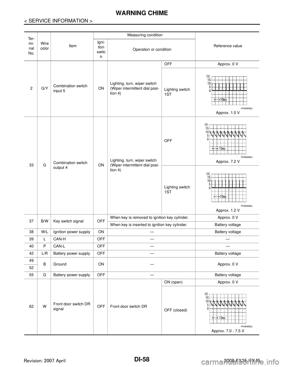
Te r -mi-
nal
No. Wire
color Item Measuring condition
Reference value
Igni-
tion
switc h Operation or condition
2G/Y Combination switch
input 5 ONLighting, turn, wiper switch
(Wiper intermittent dial posi-
tion 4) OFF Approx. 0 V
Lighting switch
1ST
Approx. 1.0 V
33 G Combination switch
output 4 ONLighting, turn, wiper switch
(Wiper intermittent dial posi-
tion 4) OFF
Approx. 7.2 V
Lighting switch
1ST Approx. 1.2 V
37 B/W Key switch signal OFF When key is removed to ignition key cylinder. Approx. 0 V
When key is inserted to ignition key cylinder. Battery voltage
38 W/L Ignition power supply ON — Battery voltage
39 L CAN-H OFF — —
40 P CAN-L OFF — —
42 L/R Battery power supply OFF — Battery voltage
49 B Ground ON — Approx. 0 V
52
55 G Battery power supp ly OFF — Battery voltage
62 W Front door switch DR
signal
OFF Front door switch DR ON (open) Approx. 0 V
OFF (closed)
Approx. 7.0 - 7.5 V
PKIB4959J
PKIB4960J
PKIB4958J
PKIB4960J
3AA93ABC3ACD3AC03ACA3AC03AC63AC53A913A773A893A873A873A8E3A773A983AC73AC93AC03AC3
3A893A873A873A8F3A773A9D3AAF3A8A3A8C3A863A9D3AAF3A8B3A8C
Page 1185 of 3924
WARNING CHIMEDI-59
< SERVICE INFORMATION >
C
DE
F
G H
I
J
L
M A
B
DI
N
O P
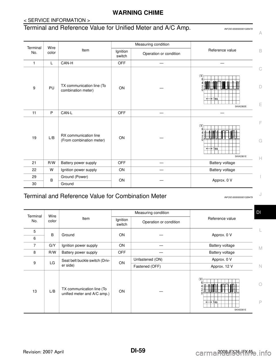
Terminal and Reference Value for Unified Meter and A/C Amp.INFOID:0000000001328478
Terminal and Reference Value for Combination MeterINFOID:0000000001328479
Te r m i n a l
No. Wire
color Item Measuring condition
Reference value
Ignition
switch Operation or condition
1 L CAN-H OFF — —
9PU TX communication line (To
combination meter) ON —
11 P C A N - L O F F — —
19 L/B RX communication line
(From combination meter) ON —
21 R/W Battery power supply OFF — Battery voltage
22 W Ignition power supply ON — Battery voltage
29 BGround (Power)
ON — Approx. 0 V
30 Ground
SKIA3362E
SKIA3361E
Te r m i n a l
No. Wire
color Item Measuring condition
Reference value
Ignition
switch Operation or condition
5 B Ground ON — Approx. 0 V
6
7 G/Y Ignition power supply ON — Battery voltage
8 R/W Battery power supply OFF — Battery voltage
9LG Seat belt buckle switch (Driv-
er side) ONUnfastened (ON) Approx. 0 V
Fastened (OFF) Approx. 12 V
13 L/B TX communication line (To
unified meter and A/C amp.)
ON —
SKIA3361E
3AA93ABC3ACD3AC03ACA3AC03AC63AC53A913A773A893A873A873A8E3A773A983AC73AC93AC03AC3
3A893A873A873A8F3A773A9D3AAF3A8A3A8C3A863A9D3AAF3A8B3A8C
Page 1188 of 3924
DI-62
< SERVICE INFORMATION >
WARNING CHIME
OK or NG
OK >> GO TO 2.
NG >> Be sure to eliminate cause of malfunction before installing new fuse or fusible link. Refer to PG-3
.
2.CHECK POWER SUPPLY CIRCUIT
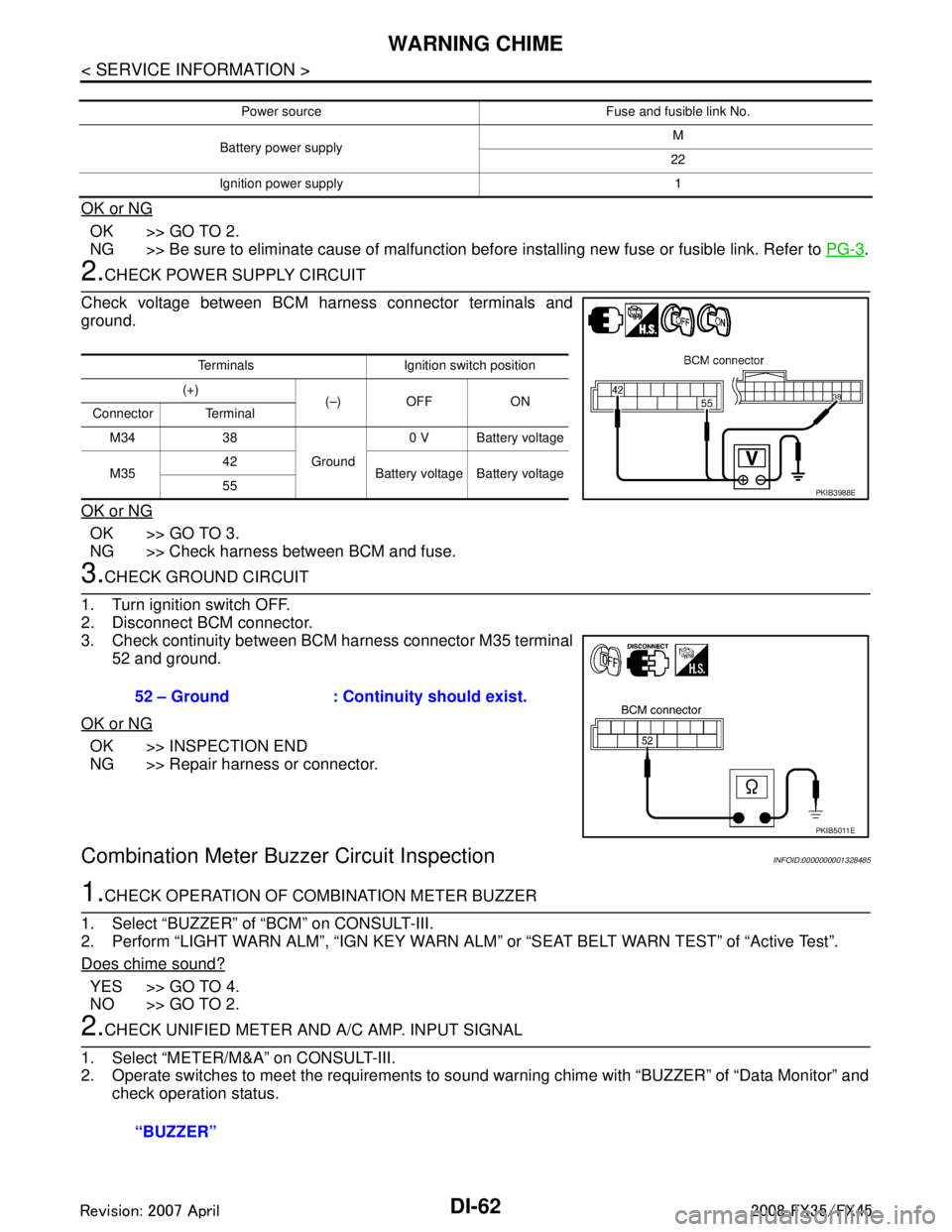
Check voltage between BCM harness connector terminals and
ground.
OK or NG
OK >> GO TO 3.
NG >> Check harness between BCM and fuse.
3.CHECK GROUND CIRCUIT
1. Turn ignition switch OFF.
2. Disconnect BCM connector.
3. Check continuity between BCM harness connector M35 terminal 52 and ground.
OK or NG
OK >> INSPECTION END
NG >> Repair harness or connector.
Combination Meter Buzzer Circuit InspectionINFOID:0000000001328485
1.CHECK OPERATION OF COMBINATION METER BUZZER
1. Select “BUZZER” of “BCM” on CONSULT-III.
2. Perform “LIGHT WARN ALM”, “IGN KEY WARN AL M” or “SEAT BELT WARN TEST” of “Active Test”.
Does chime sound?
YES >> GO TO 4.
NO >> GO TO 2.
2.CHECK UNIFIED METER AND A/C AMP. INPUT SIGNAL
1. Select “METER/M&A” on CONSULT-III.
2. Operate switches to meet the requirements to s ound warning chime with “BUZZER” of “Data Monitor” and
check operation status.
Power source Fuse and fusible link No.
Battery power supply M
22
Ignition power supply 1
Terminals Ignition switch position
(+) (–) OFF ON
Connector Terminal
M34 38 Ground0 V Battery voltage
M35 42
Battery voltage Battery voltage
55
PKIB3988E
52 – Ground : Continui ty should exist.
PKIB5011E
“BUZZER”
3AA93ABC3ACD3AC03ACA3AC03AC63AC53A913A773A893A873A873A8E3A773A983AC73AC93AC03AC3
3A893A873A873A8F3A773A9D3AAF3A8A3A8C3A863A9D3AAF3A8B3A8C
Page 1189 of 3924

WARNING CHIMEDI-63
< SERVICE INFORMATION >
C
DE
F
G H
I
J
L
M A
B
DI
N
O P
OK or NG
OK >> GO TO 3.
NG >> Replace BCM. Refer to BCS-13, "
Removal and Installation of BCM".
3.CHECK BATTERY POWER SUPPLY CIRCUIT OF COMBINATION METER
Check battery power supply circuit of combination meter. Refer to DI-16, "
Power Supply and Ground Circuit
Inspection".
OK or NG
OK >> Replace combination meter.
NG >> Check harness between combination meter and fuse.
4.CHECK BATTERY POWER SUPPLY CIRCUI T OF UNIFIED METER AND A/C AMP.
Check battery power supply circuit of unified meter and A/C amp. Refer to DI-29, "
Power Supply and Ground
Circuit Inspection".
OK or NG
OK >> INSPECTION END
NG >> Check harness between unified meter and A/C amp. and fuse.
Front Door Switch (Drive r Side) Signal InspectionINFOID:0000000001328486
1.CHECK BCM INPUT SIGNAL
With CONSULT-III
1. Select “BCM” on consult-III.
2. With “Data Monitor” of “BUZZER”, confirm “D OOR SW-DR” when the driver side door is operated.
Without CONSULT-III
Check voltage between BCM harness connector B14 terminal 62 and ground.
OK or NG
OK >> INSPECTION END
NG >> GO TO 2.
2.CHECK FRONT DOOR SWIT CH (DRIVER SIDE) CIRCUIT
1. Turn ignition switch OFF.
2. Disconnect BCM connector and front door switch (driver side) connector. When meeting the requirements
to sound warning chime
: On
Except above : Off
“DOOR SW-DR”
When driver side door is opened : On
When driver side door is closed : Off
62 – Ground
When driver side door is opened : Approx. 0 V
When driver side door is closed : Approx. 12 V
3AA93ABC3ACD3AC03ACA3AC03AC63AC53A913A773A893A873A873A8E3A773A983AC73AC93AC03AC3
3A893A873A873A8F3A773A9D3AAF3A8A3A8C3A863A9D3AAF3A8B3A8C
Page 1191 of 3924
WARNING CHIMEDI-65
< SERVICE INFORMATION >
C
DE
F
G H
I
J
L
M A
B
DI
N
O P
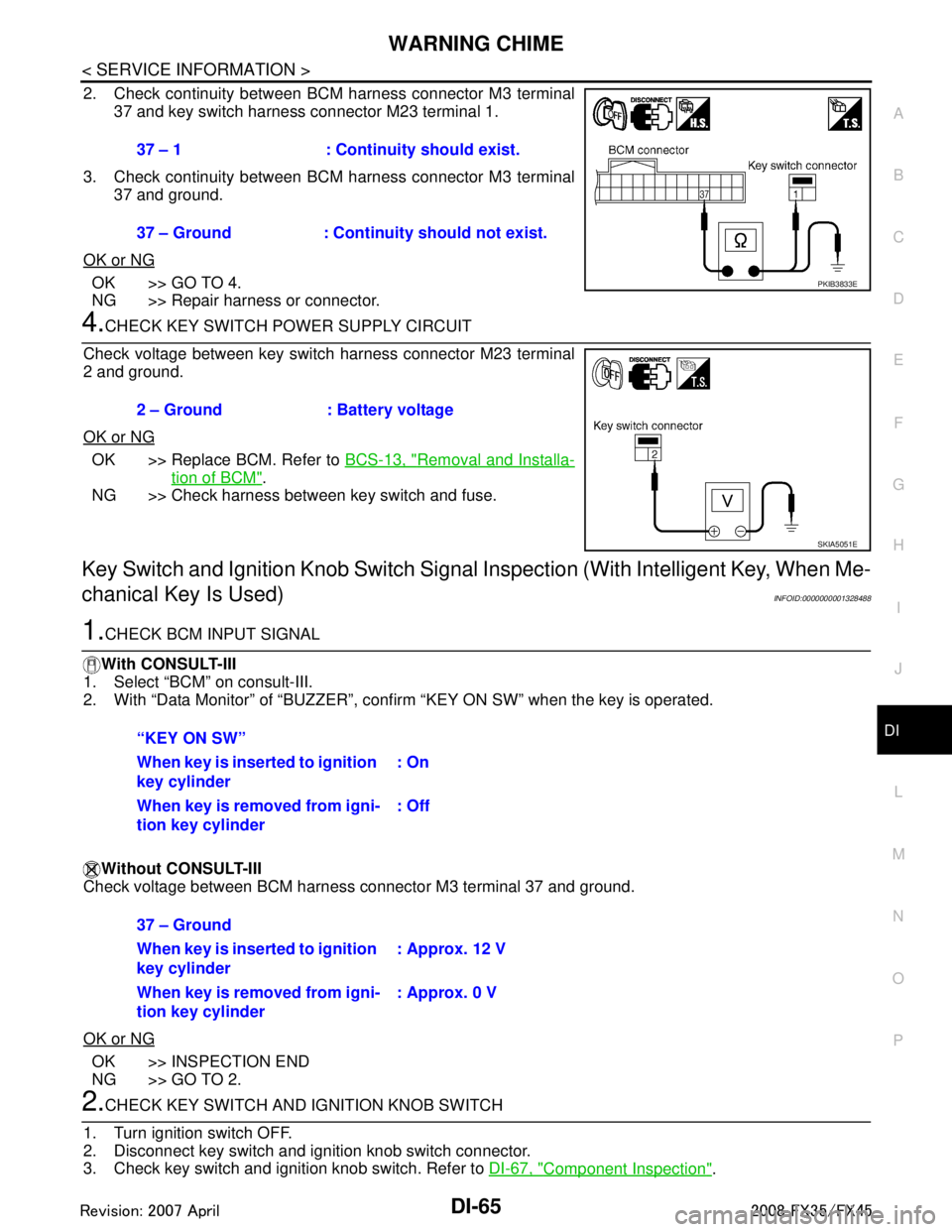
2. Check continuity between BCM harness connector M3 terminal 37 and key switch harness connector M23 terminal 1.
3. Check continuity between BCM harness connector M3 terminal 37 and ground.
OK or NG
OK >> GO TO 4.
NG >> Repair harness or connector.
4.CHECK KEY SWITCH POWER SUPPLY CIRCUIT
Check voltage between key switch harness connector M23 terminal
2 and ground.
OK or NG
OK >> Replace BCM. Refer to BCS-13, "Removal and Installa-
tion of BCM".
NG >> Check harness between key switch and fuse.
Key Switch and Ignition Knob Switch Signal Inspection (With Intelligent Key, When Me-
chanical Key Is Used)
INFOID:0000000001328488
1.CHECK BCM INPUT SIGNAL
With CONSULT-III
1. Select “BCM” on consult-III.
2. With “Data Monitor” of “BUZZER”, conf irm “KEY ON SW” when the key is operated.
Without CONSULT-III
Check voltage between BCM harness connector M3 terminal 37 and ground.
OK or NG
OK >> INSPECTION END
NG >> GO TO 2.
2.CHECK KEY SWITCH AND IG NITION KNOB SWITCH
1. Turn ignition switch OFF.
2. Disconnect key switch and i gnition knob switch connector.
3. Check key switch and ignition knob switch. Refer to DI-67, "
Component Inspection".
37 – 1 : Continuity should exist.
37 – Ground : Continuity should not exist.
PKIB3833E
2 – Ground : Battery voltage
SKIA5051E
“KEY ON SW”
When key is inserted to ignition
key cylinder
: On
When key is removed from igni-
tion key cylinder : Off
37 – Ground
When key is inserted to ignition
key cylinder: Approx. 12 V
When key is removed from igni-
tion key cylinder : Approx. 0 V
3AA93ABC3ACD3AC03ACA3AC03AC63AC53A913A773A893A873A873A8E3A773A983AC73AC93AC03AC3
3A893A873A873A8F3A773A9D3AAF3A8A3A8C3A863A9D3AAF3A8B3A8C
Page 1192 of 3924
DI-66
< SERVICE INFORMATION >
WARNING CHIME
OK or NG
OK >> GO TO 3.
NG >> Replace key switch and ignition knob switch.
3.CHECK KEY SWITCH AND IGNITION KNOB SWITCH CIRCUIT
1. Disconnect BCM connector.
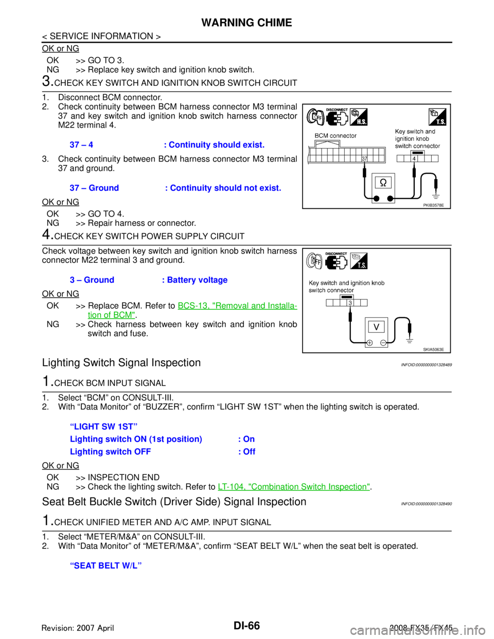
2. Check continuity between BCM harness connector M3 terminal 37 and key switch and ignition knob switch harness connector
M22 terminal 4.
3. Check continuity between BCM harness connector M3 terminal 37 and ground.
OK or NG
OK >> GO TO 4.
NG >> Repair harness or connector.
4.CHECK KEY SWITCH PO WER SUPPLY CIRCUIT
Check voltage between key switch and ignition knob switch harness
connector M22 terminal 3 and ground.
OK or NG
OK >> Replace BCM. Refer to BCS-13, "Removal and Installa-
tion of BCM".
NG >> Check harness between key switch and ignition knob switch and fuse.
Lighting Switch Signal InspectionINFOID:0000000001328489
1.CHECK BCM INPUT SIGNAL
1. Select “BCM” on CONSULT-III.
2. With “Data Monitor” of “BUZZER”, confirm “LIG HT SW 1ST” when the lighting switch is operated.
OK or NG
OK >> INSPECTION END
NG >> Check the lighting switch. Refer to LT-104, "
Combination Switch Inspection".
Seat Belt Buckle Switch (Driver Side) Signal InspectionINFOID:0000000001328490
1.CHECK UNIFIED METER AND A/C AMP. INPUT SIGNAL
1. Select “METER/M&A” on CONSULT-III.
2. With “Data Monitor” of “MET ER/M&A”, confirm “SEAT BELT W/L” when the seat belt is operated.
37 – 4 : Continuity should exist.
37 – Ground : Continuity should not exist.
PKIB3578E
3 – Ground : Battery voltage
SKIA5063E
“LIGHT SW 1ST”
Lighting switch ON (1st position) : On
Lighting switch OFF : Off
“SEAT BELT W/L”
3AA93ABC3ACD3AC03ACA3AC03AC63AC53A913A773A893A873A873A8E3A773A983AC73AC93AC03AC3
3A893A873A873A8F3A773A9D3AAF3A8A3A8C3A863A9D3AAF3A8B3A8C