2008 INFINITI FX35 battery
[x] Cancel search: batteryPage 1060 of 3924
![INFINITI FX35 2008 Service Manual
TROUBLE DIAGNOSIS FOR SYSTEMBRC-45
< SERVICE INFORMATION > [VDC/TCS/ABS]
C
D
E
G H
I
J
K L
M A
B
BRC
N
O P
2. Reconnect connectors and perform an ABS actuator and electric unit (control unit) self-d INFINITI FX35 2008 Service Manual
TROUBLE DIAGNOSIS FOR SYSTEMBRC-45
< SERVICE INFORMATION > [VDC/TCS/ABS]
C
D
E
G H
I
J
K L
M A
B
BRC
N
O P
2. Reconnect connectors and perform an ABS actuator and electric unit (control unit) self-d](/manual-img/42/57017/w960_57017-1059.png)
TROUBLE DIAGNOSIS FOR SYSTEMBRC-45
< SERVICE INFORMATION > [VDC/TCS/ABS]
C
D
E
G H
I
J
K L
M A
B
BRC
N
O P
2. Reconnect connectors and perform an ABS actuator and electric unit (control unit) self-diagnosis again.
OK or NG
OK >> Connector terminal contact is loose, damaged, open or shorted.
NG >> GO TO 3.
3.CHECK STEERING ANGLE SENSOR HARNESS
1. Check CAN communication circuit. Refer to BRC-48, "
DTC U1000 CAN COMM CIRCUIT".
2. Turn ignition switch OFF and disconnec t steering angle sensor connector M14.
3. Check continuity between steering angle sensor harness con- nector and ground.
4. Check voltage between steering angle sensor harness connec- tor and ground.
OK or NG
OK >> GO TO 4.
NG >> If the open or short in harness, repair or replace har- ness.
4.CHECK STEERING WHEEL PLAY
Check steering wheel play. Refer to PS-9, "
On-Vehicle Inspection and Service".
OK or NG
OK >> GO TO 5
NG >> Adjust steering wheel play.
5.PERFORM DATA MONITOR
1. Connect steering angle sensor and ABS actuator and electric unit (control unit) connectors.
2. Perform “DATA MONITOR” of the “STEERING ANGL E SIGNAL” to check if the status is normal.
OK or NG
OK >> Perform ABS actuator and electric unit (control unit) self-diagnosis again.
NG >> Replace steering angle sensor and adjust neutra l position of steering angle sensor. Refer to BRC-
8, "Adjustment of Steering Angle Sensor Neutral Position".
DTC C1144 ST ANG SEN SIGNALINFOID:0000000001327688
INSPECTION PROCEDURE
1.CHECK SELF-DIAGNOSTIC RESULTS (1)
Check self-diagnostic results.
Steering angle sensor Ground Continuity
2—Yes
SFIA1189E
Steering angle sensor Ground Voltage
3— Battery voltage
(Approx. 12 V)
SFIA1190E
Steering condition Data monitor display
Straight-ahead -3.5 deg - +3.5 deg
Turn wheel to the right by 90 °. Approx. -90 deg
Turn wheel to the left by 90 °. Approx. +90 deg
3AA93ABC3ACD3AC03ACA3AC03AC63AC53A913A773A893A873A873A8E3A773A983AC73AC93AC03AC3
3A893A873A873A8F3A773A9D3AAF3A8A3A8C3A863A9D3AAF3A8B3A8C
Page 1069 of 3924
![INFINITI FX35 2008 Service Manual
BRC-54
< SERVICE INFORMATION >[VDC/TCS/ABS]
ACTUATOR AND ELECTRIC UNIT (ASSEMBLY)
ACTUATOR AND ELECTRIC UNIT (ASSEMBLY)
Removal and InstallationINFOID:0000000001327700
REMOVAL
1. Disconnect ABS actua INFINITI FX35 2008 Service Manual
BRC-54
< SERVICE INFORMATION >[VDC/TCS/ABS]
ACTUATOR AND ELECTRIC UNIT (ASSEMBLY)
ACTUATOR AND ELECTRIC UNIT (ASSEMBLY)
Removal and InstallationINFOID:0000000001327700
REMOVAL
1. Disconnect ABS actua](/manual-img/42/57017/w960_57017-1068.png)
BRC-54
< SERVICE INFORMATION >[VDC/TCS/ABS]
ACTUATOR AND ELECTRIC UNIT (ASSEMBLY)
ACTUATOR AND ELECTRIC UNIT (ASSEMBLY)
Removal and InstallationINFOID:0000000001327700
REMOVAL
1. Disconnect ABS actuator and electric unit (control unit) connector.
2. Loosen brake tube flare nuts, then remove brake tubes
from ABS actuator and electric unit (control unit).
3. Remove LH side fender protector. Refer to EI-24
.
4. Remove ABS actuator and electric unit (control unit) mounting nuts.
5. Remove ABS actuator and electric unit (control unit) from vehicle.
CAUTION:
Be careful of the following wh en removing ABS actuator and electric unit (control unit).
If the part number on the part number label (p asted on actuator upper surface) is the same, ABS
actuator and electric unit (c ontrol unit) can not be used on another vehicle.
If it is used on another vehicle, ABS warning lamp, SLIP indicator lamp and VDC OFF indicator lamp
may turn ON or VDC/TCS/ABS may not operate normally.
When replacing ABS actuator an d electric unit (control unit), must use new service parts.
Before servicing, disconnect battery cables.
To remove brake tube, use a flare nut torque wrench to prevent flare nuts and brake tube from being
damaged. To install, use a flare nut torque wren ch (commercial service tool) and tighten to the spec-
ified torque.
Do not apply excessive impact to actuator, such as dropping it.
Do not remove and install ABS actuator and el ectric unit (control unit) by holding harness.
INSTALLATION
Note the following, and install in the reverse order of removal.
CAUTION:
Be careful of the following wh en installing ABS actuator and electric unit (control unit).
Tighten the mounting bolts and nuts to the specified torque.
After the work, bleed air from brake piping. Refer to BR-8, "
Bleeding Brake System".
After installing vehicle harness connector in th e actuator, make sure connector is securely locked.
When replacing ABS actuator and el ectric unit (control unit), calibrate steering angle sensor neutral
position and decel G sensor. Refer to BRC-8
.
PFIA0601E
3AA93ABC3ACD3AC03ACA3AC03AC63AC53A913A773A893A873A873A8E3A773A983AC73AC93AC03AC3
3A893A873A873A8F3A773A9D3AAF3A8A3A8C3A863A9D3AAF3A8B3A8C
Page 1133 of 3924
COMBINATION METERSDI-7
< SERVICE INFORMATION >
C
DE
F
G H
I
J
L
M A
B
DI
N
O P
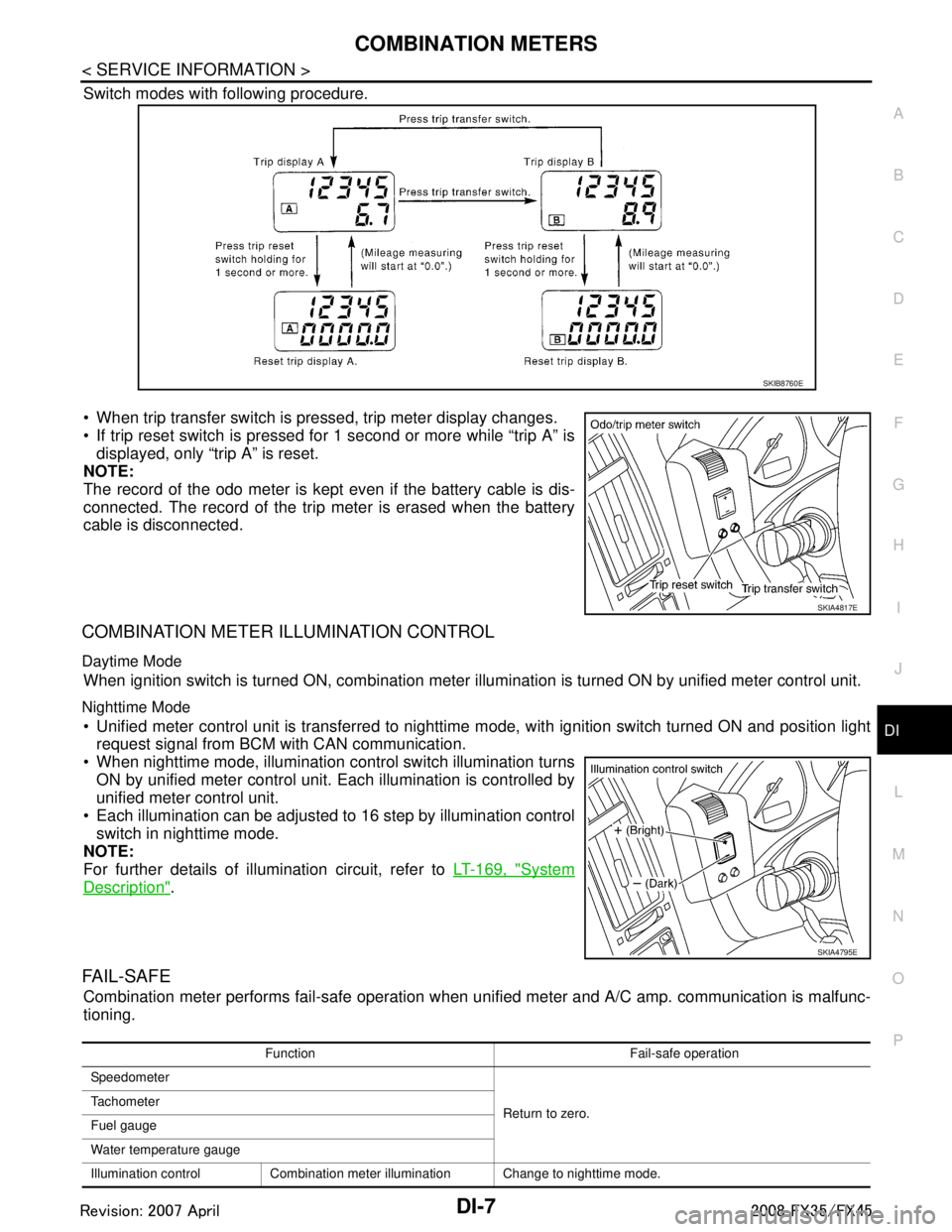
Switch modes with following procedure.
When trip transfer switch is pressed, trip meter display changes.
If trip reset switch is pressed for 1 second or more while “trip A” is displayed, only “trip A” is reset.
NOTE:
The record of the odo meter is kept even if the battery cable is dis-
connected. The record of the trip meter is erased when the battery
cable is disconnected.
COMBINATION METER ILLUMINATION CONTROL
Daytime Mode
When ignition switch is turned ON, combination meter il lumination is turned ON by unified meter control unit.
Nighttime Mode
Unified meter control unit is transferred to nighttime mode, with ignitio\
n switch turned ON and position light
request signal from BCM with CAN communication.
When nighttime mode, illumination c ontrol switch illumination turns
ON by unified meter control unit. Each illumination is controlled by
unified meter control unit.
Each illumination can be adjusted to 16 step by illumination control switch in nighttime mode.
NOTE:
For further details of illumination circuit, refer to LT-169, "
System
Description".
FA I L - S A F E
Combination meter performs fail-safe operation when unified meter and A/C amp. communication is malfunc-
tioning.
SKIB8760E
SKIA4817E
SKIA4795E
Function Fail-safe operation
Speedometer
Return to zero.
Tachometer
Fuel gauge
Water temperature gauge
Illumination control Combination meter illumination Change to nighttime mode.
3AA93ABC3ACD3AC03ACA3AC03AC63AC53A913A773A893A873A873A8E3A773A983AC73AC93AC03AC3
3A893A873A873A8F3A773A9D3AAF3A8A3A8C3A863A9D3AAF3A8B3A8C
Page 1139 of 3924
COMBINATION METERSDI-13
< SERVICE INFORMATION >
C
DE
F
G H
I
J
L
M A
B
DI
N
O P
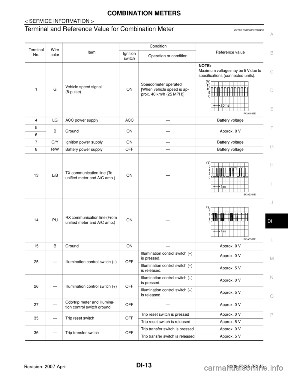
Terminal and Reference Va lue for Combination MeterINFOID:0000000001328438
Te r m i n a l
No. Wire
color Item Condition
Reference value
Ignition
switch Operation or condition
1G Vehicle speed signal
(8-pulse)
ONSpeedometer operated
[When vehicle speed is ap-
prox. 40 km/h (25 MPH)] NOTE:
Maximum voltage may be 5 V due to
specifications (connected units).
4 LG ACC power supply ACC — Battery voltage
5 B Ground ON — Approx. 0 V
6
7 G/Y Ignition power supply ON — Battery voltage
8 R/W Battery power supply OFF — Battery voltage
13 L/B TX communication line (To
unified meter and A/C amp.)
ON —
14 PU RX communication line (From
unified meter and A/C amp.) ON —
15 B Ground ON — Approx. 0 V
25 — Illumination control switch (–) OFF Illumination control switch (–)
is pressed.
Approx. 0 V
Illumination control switch (–)
is released. Approx. 5 V
26 — Illumination control switch (+) OFF Illumination control switch (+)
is pressed.
Approx. 0 V
Illumination control switch (+)
is released. Approx. 5 V
27 — Odo/trip meter and illumina-
tion control switch ground
OFF — Approx. 0 V
35 — Trip reset switch OFF Trip reset switch is pressed Approx. 0 V
Trip reset switch is released Approx. 5 V
36 — Trip transfer switch OFF Trip transfer switch is pressed Approx. 0 V
Trip transfer switch is released Approx. 5 V
PKIA1935E
SKIA3361E
SKIA3362E
3AA93ABC3ACD3AC03ACA3AC03AC63AC53A913A773A893A873A873A8E3A773A983AC73AC93AC03AC3
3A893A873A873A8F3A773A9D3AAF3A8A3A8C3A863A9D3AAF3A8B3A8C
Page 1140 of 3924
DI-14
< SERVICE INFORMATION >
COMBINATION METERS
Terminal and Reference Value for Unified Meter and A/C Amp
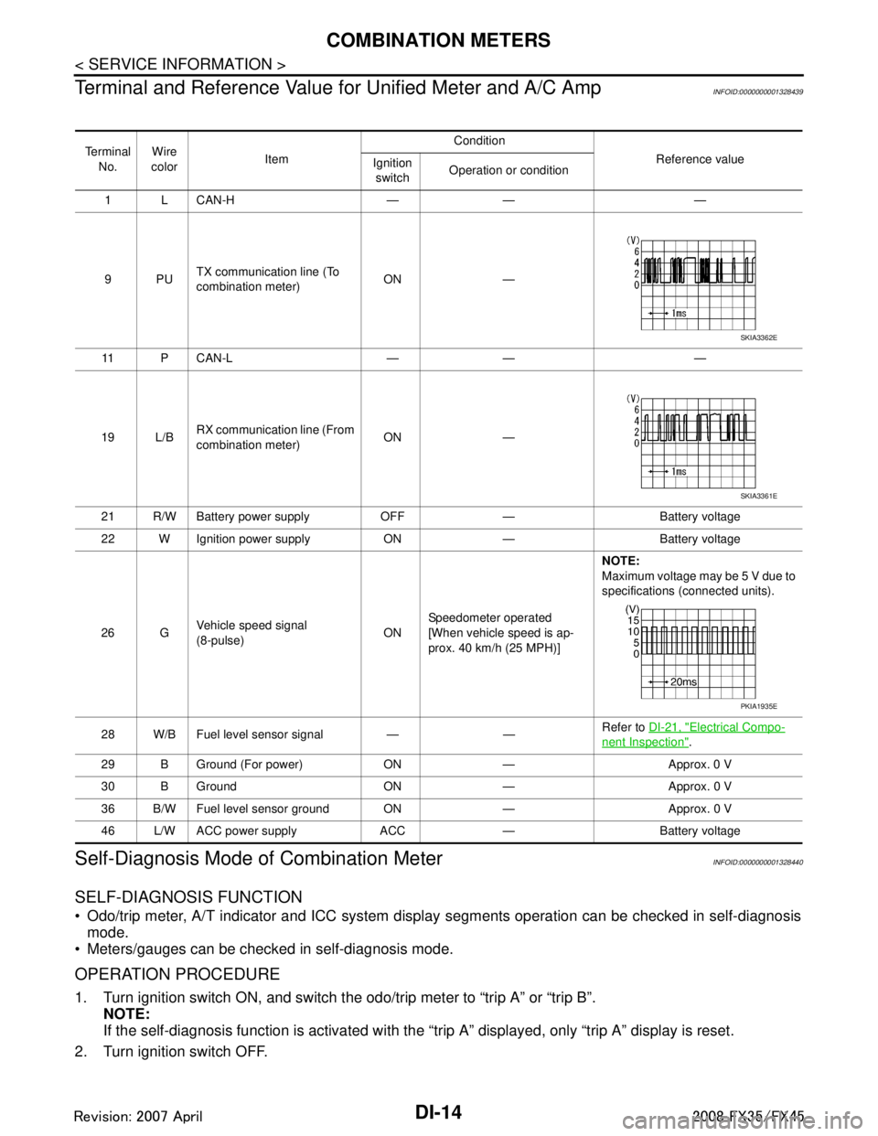
INFOID:0000000001328439
Self-Diagnosis Mode of Combination MeterINFOID:0000000001328440
SELF-DIAGNOSIS FUNCTION
Odo/trip meter, A/T indicator and ICC system disp lay segments operation can be checked in self-diagnosis
mode.
Meters/gauges can be checked in self-diagnosis mode.
OPERATION PROCEDURE
1. Turn ignition switch ON, and switch the odo/trip meter to “trip A” or “trip B”. NOTE:
If the self-diagnosis function is activated with the “t rip A” displayed, only “trip A” display is reset.
2. Turn ignition switch OFF.
Te r m i n a l No. Wire
color Item Condition
Reference value
Ignition
switch Operation or condition
1 L CAN-H — — —
9PU TX communication line (To
combination meter) ON —
11 P C A N - L — — —
19 L/B RX communication line (From
combination meter) ON —
21 R/W Battery power supply OFF — Battery voltage
22 W Ignition power supply ON — Battery voltage
26 G Vehicle speed signal
(8-pulse)
ONSpeedometer operated
[When vehicle speed is ap-
prox. 40 km/h (25 MPH)] NOTE:
Maximum voltage may be 5 V due to
specifications (connected units).
28 W/B Fuel level sensor signal — — Refer to
DI-21, "
Electrical Compo-
nent Inspection".
29 B Ground (For power) ON — Approx. 0 V
30 B Ground ON — Approx. 0 V
36 B/W Fuel level sensor ground ON — Approx. 0 V
46 L/W ACC power supply ACC — Battery voltage
SKIA3362E
SKIA3361E
PKIA1935E
3AA93ABC3ACD3AC03ACA3AC03AC63AC53A913A773A893A873A873A8E3A773A983AC73AC93AC03AC3
3A893A873A873A8F3A773A9D3AAF3A8A3A8C3A863A9D3AAF3A8B3A8C
Page 1142 of 3924
DI-16
< SERVICE INFORMATION >
COMBINATION METERS
Perform self-diagnosis mode of combination meter. Refer to DI-14, "Self-Diagnosis Mode of Combination
Meter".
Does self-diagnosis function operate?
YES >> GO TO 2.
NO >> GO TO 3.
2.CHECK UNIFIED METER AND A/C AMP. (CONSULT-III)
Perform self-diagnosis of unified meter and A/C amp. Refer to DI-27, "
CONSULT-III Function (METER/M&A)".
Self-diagnosis results
No malfunction detected >> INSPECTION END
Malfunction detected >> Check applicable parts, and repair or replace corresponding parts.
3.CHECK POWER SUPPLY AND GROUND CIRCUIT OF COMBINATION METER
Check power supply and ground circuit of combination meter. Refer to DI-16, "
Power Supply and Ground Cir-
cuit Inspection".
OK or NG
OK >> Check odo/trip meter switch. Refer to DI-21, "Odo/Trip Meter and Illumination Control Switch
Inspection".
NG >> Repair malfunctioning part.
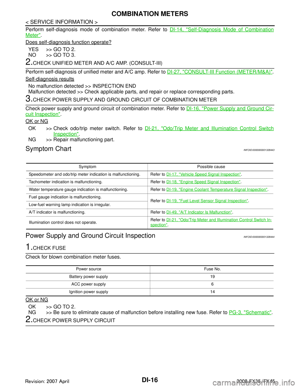
Symptom ChartINFOID:0000000001328443
Power Supply and Ground Circuit InspectionINFOID:0000000001328444
1.CHECK FUSE
Check for blown combination meter fuses.
OK or NG
OK >> GO TO 2.
NG >> Be sure to eliminate cause of malfunction before installing new fuse. Refer to PG-3, "
Schematic".
2.CHECK POWER SUPPLY CIRCUIT
Symptom Possible cause
Speedometer and odo/trip meter indication is malfunctioning. Refer to DI-17, "
Vehicle Speed Signal Inspection".
Tachometer indication is malfunctioning. Refer to DI-18, "
Engine Speed Signal Inspection".
Water temperature gauge indication is malfunctioning. Refer to DI-19, "
Engine Coolant Temperature Signal Inspection".
Fuel gauge indication is malfunctioning. Refer to DI-19, "
Fuel Level Sensor Signal Inspection".
Low-fuel warning lamp indication is irregular.
A/T indicator is malfunctioning. Refer to DI-49, "
A/T Indicator Is Malfunction".
Illumination control does not operate. Refer to
DI-21, "
Odo/Trip Meter and Illumination Control Switch In-
spection".
Power source Fuse No.
Battery power supply 19 ACC power supply 6
Ignition power supply 14
3AA93ABC3ACD3AC03ACA3AC03AC63AC53A913A773A893A873A873A8E3A773A983AC73AC93AC03AC3
3A893A873A873A8F3A773A9D3AAF3A8A3A8C3A863A9D3AAF3A8B3A8C
Page 1143 of 3924
COMBINATION METERSDI-17
< SERVICE INFORMATION >
C
DE
F
G H
I
J
L
M A
B
DI
N
O P
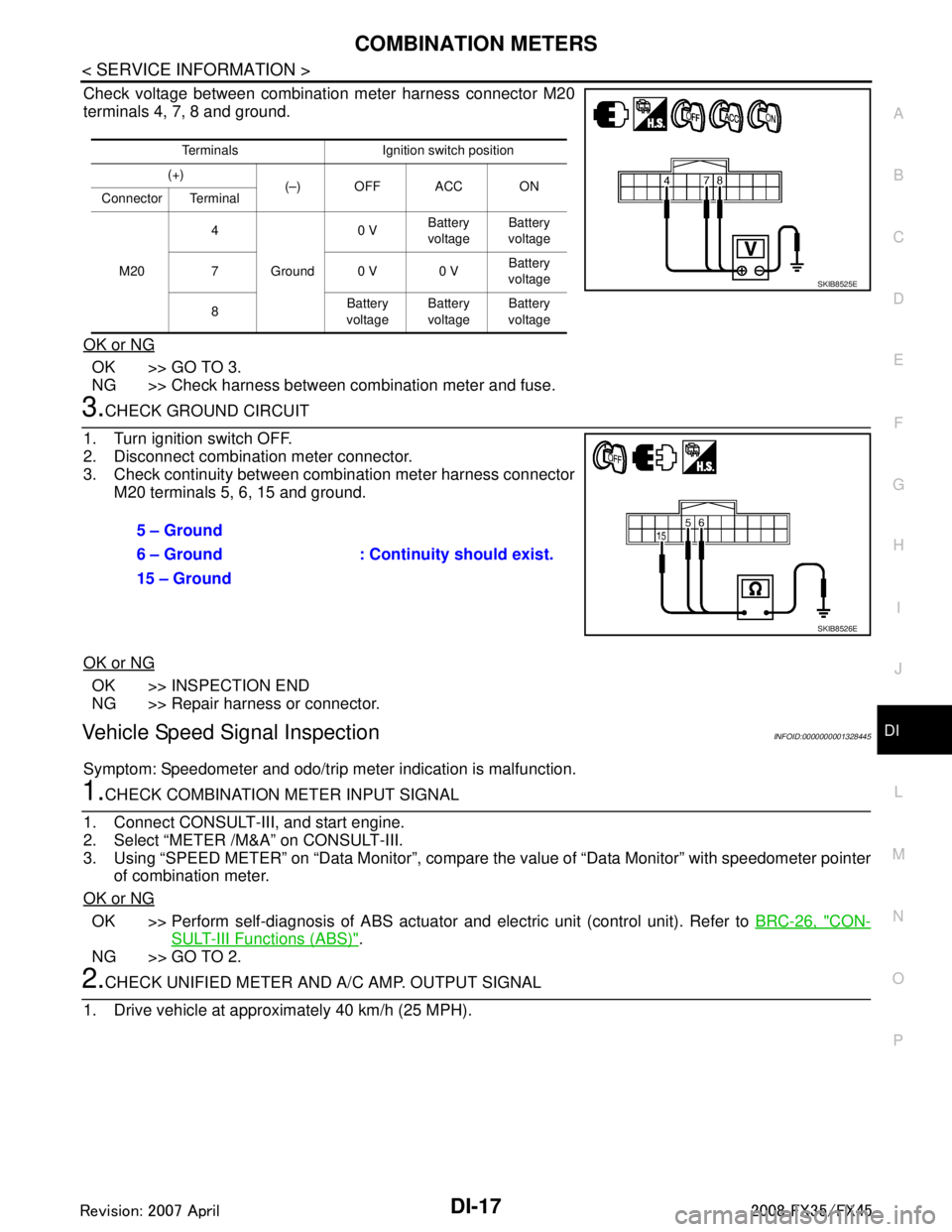
Check voltage between combination meter harness connector M20
terminals 4, 7, 8 and ground.
OK or NG
OK >> GO TO 3.
NG >> Check harness between combination meter and fuse.
3.CHECK GROUND CIRCUIT
1. Turn ignition switch OFF.
2. Disconnect combination meter connector.
3. Check continuity between combination meter harness connector M20 terminals 5, 6, 15 and ground.
OK or NG
OK >> INSPECTION END
NG >> Repair harness or connector.
Vehicle Speed Signal InspectionINFOID:0000000001328445
Symptom: Speedometer and odo/trip meter indication is malfunction.
1.CHECK COMBINATION METER INPUT SIGNAL
1. Connect CONSULT-III, and start engine.
2. Select “METER /M&A” on CONSULT-III.
3. Using “SPEED METER” on “Data Moni tor”, compare the value of “Data Monitor” with speedometer pointer
of combination meter.
OK or NG
OK >> Perform self-diagnosis of ABS actuator and electric unit (control unit). Refer to BRC-26, "CON-
SULT-III Functions (ABS)".
NG >> GO TO 2.
2.CHECK UNIFIED METER AND A/ C AMP. OUTPUT SIGNAL
1. Drive vehicle at approximately 40 km/h (25 MPH).
Terminals Ignition switch position
(+) (–) OFF ACC ON
Connector Terminal
M20 4
Ground 0 V
Battery
voltage Battery
voltage
70 V0 V Battery
voltage
8 Battery
voltage Battery
voltage Battery
voltage
SKIB8525E
5 – Ground
: Continuity should exist.
6 – Ground
15 – Ground
SKIB8526E
3AA93ABC3ACD3AC03ACA3AC03AC63AC53A913A773A893A873A873A8E3A773A983AC73AC93AC03AC3
3A893A873A873A8F3A773A9D3AAF3A8A3A8C3A863A9D3AAF3A8B3A8C
Page 1154 of 3924

DI-28
< SERVICE INFORMATION >
UNIFIED METER AND A/C AMP
SELF-DIAG RESULTS
Display Item List
NOTE:
“TIME” means the following.
0: Means detected malfunction at present. (From malfunction detection to turning ignition switch OFF)
1 - 63: Means detected malfunction in the past . (Displays the number of ignition switch OFF → ON after
detecting malfunction. “Self Diagnostic Result” is erased when exceeding “63”.)
DATA MONITOR
Display Item List
X: Applicable
System Diagnosis mode Description
METER A/C AMP Self Diagnostic Result
Unified meter and A/C amp. checks the conditions and displays
memorized error.
CAN DIAG SUPPORT MNTR The results of transmit/receive diagnosis of CAN communication
can be read.
Data Monitor Displays unified meter and A/C amp. input data in real time.
Display item [Code] Malfunction is detected when... Reference
page
CAN COMM CIRC [U1000] When unified meter and A/C amp. is not transmitting or receiving CAN communication
signal for 2 seconds or more. DI-30
METER COMM CIRC [B2202]Malfunction is detected in communication of between combination meter and unified
meter and A/C amp.
DI-30
VEHICLE SPEED CIRC [B2205]When an erroneous speed signal is input for 1 second.
NOTE:
Even when there is no malfunction on speed signal system, malfunction may be misin-
terpreted when battery has low voltage (when maintaining 7 - 8 V for about 2 seconds). DI-32
Display item [Unit]
MAIN
SIGNALS SELECTION
FROM MENU Contents
SPEED METER [km/h] or [mph] X X Displays the value of vehicle speed signal, which is input from
ABS actuator and electric unit (control unit).
SPEED OUTPUT [km/h] or [mph] X X Displays the value of vehicle speed signal, which is transmitted
to each unit with CAN communication.
TACHO METER [rpm] X X Displays the value of engine speed signal, which is input from
ECM.
W TEMP METER [ °C] or [ °F] X X Displays the value of engine coolant temperature signal, which is
input from ECM.
FUEL METER [lit.] X X Displays the value, which processes a resistance signal from fuel
gauge.
DISTANCE [km] or [mile] X X Displays the value, which is calculated by vehicle speed signal
from ABS actuator and electric unit
(control unit), fuel gauge and
fuel consumption from ECM.
FUEL W/L [On/Off] X X Indicates [On/Off] condition of low-fuel warning lamp.
MIL [On/Off] X Indicates [On/Off] condition of malfunction indicator lamp.
AIR PRES W/L [On/Off] X Indicates [On/Off] condition of low tire pressure warning lamp.
SEAT BELT W/L [On/Off]
*1X Indicates [On/Off] condition of seat belt warning lamp.
BUZZER [On/Off] X X Indicates [On/Off] condition of buzzer.
DOOR W/L [On/Off] X Indicates [On/Off] condition of door warning lamp.
HI-BEAM IND [On/Off] X Indicates [On/Off] condition of high beam indicator.
TURN IND [On/Off] X Indicates [On/Off] condition of turn indicator.
3AA93ABC3ACD3AC03ACA3AC03AC63AC53A913A773A893A873A873A8E3A773A983AC73AC93AC03AC3
3A893A873A873A8F3A773A9D3AAF3A8A3A8C3A863A9D3AAF3A8B3A8C