Page 272 of 392

265III. KEY POINTS FOR INSTALLATION1. Pre-Check
(1) The new airbag or clock spring shall be checked before being installed.
(2) Connect negative (-) terminal cable of the battery.
(3) Connect Hi-DS T to the diagnostic interface (16 connector).
(4) Turn the ignition switch ON.
(5) Read the diagnostic circuit and see if the other locations than the troubled area of the airbag are normal.
(6) Turn the ignition switch ON.
(7) Remove the negative (-) terminal cable from the battery, and protect it with insulating tape for insulation.
2. Installation of clock spring: align the clock spring and install it to the
steering wheel.
�yCenter alignment of the clock spring
Screw up the clock spring clockwise to the end, rotate it counterclock-
wise by 2.5 turns, and align it with the mark (see the figure below).
3. Install the components of the steering wheel and airbag assembly
(1) When the center of the clock spring is aligned, install the components of the steering wheel and airbag
assembly.
(2) After being installed, rotate the left and right sides of the steering wheel to position, and make sure there
is no abnormality.NOTICEIn case of scrapping an airbag, it shall be noted that the airbag shall be deployed according to the specifiedprocedures before being scrapped.
When connecting or disconnecting the Hi-DS T, turn the ignition switch OFF first.NOTICE:
Work must be started 60s after the negative (-) terminal cable is disconnected from battery.NOTICE:
If the center of the clock spring cannot be aligned, the steering wheel
will not turn midway, or cause bad performance to the clock spring
circuit, consequently hamper the normal action of the airbag.NOTICEWhen installing the components of the steering wheel and airbag assembly, attention should be given toprotect the wire harness of the clock spring from seizure.
Page 273 of 392

2664. Check after installation
(1) Slightly rotate the steering wheel left and right, make sure that there is no abnormality or noise. (Driver
airbag module, clock spring)
(2) Turn the ignition switch ON.
(3) The warning light goes on within 6s, and then goes out.
(4) The trouble shall be eliminated if the warning light remains on when the ignition switch is turned on or
after it goes out after 6s.IV. CHECKING1. Driver airbag assembly checking
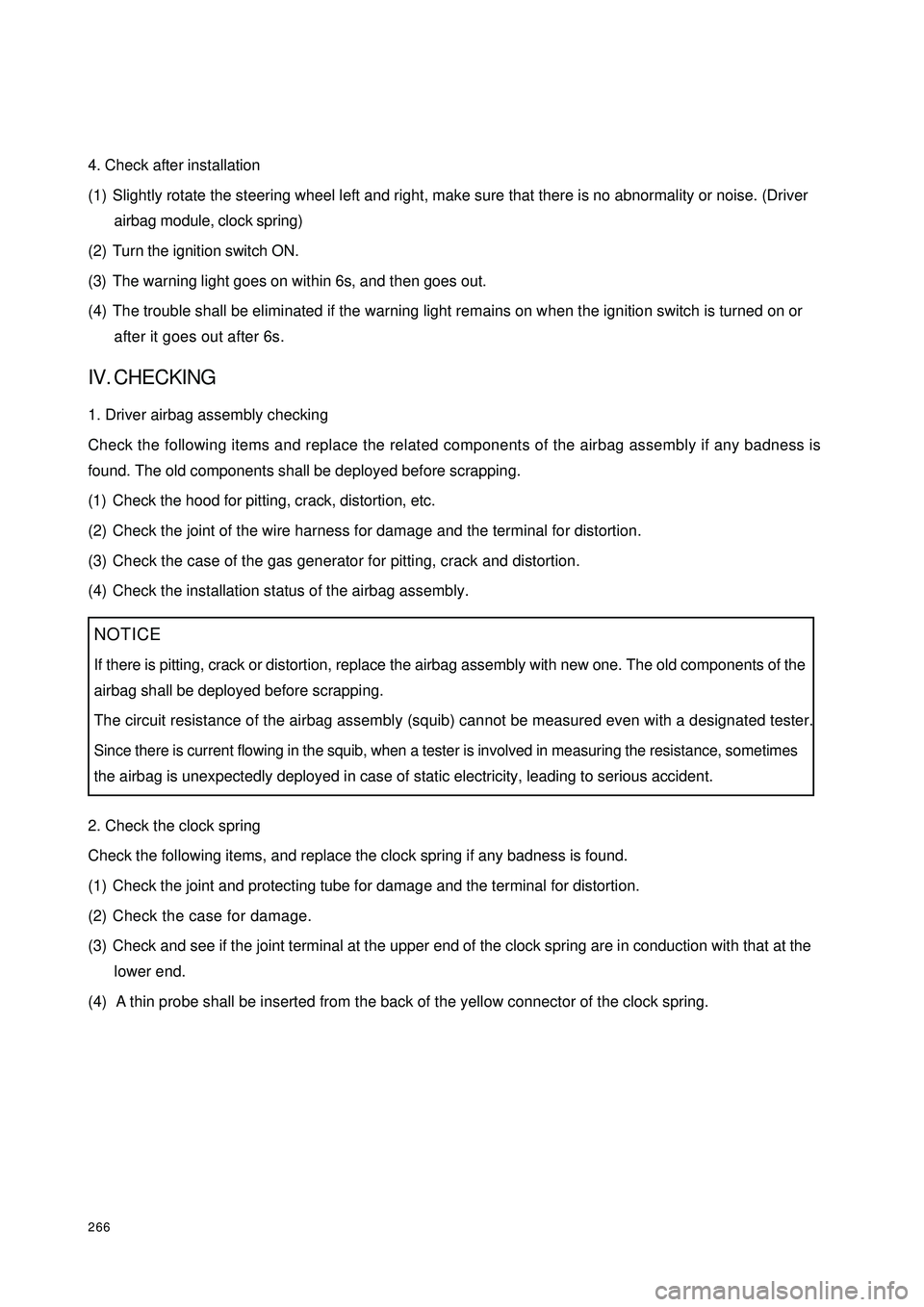
Check the following items and replace the related components of the airbag assembly if any badness is
found. The old components shall be deployed before scrapping.
(1) Check the hood for pitting, crack, distortion, etc.
(2) Check the joint of the wire harness for damage and the terminal for distortion.
(3) Check the case of the gas generator for pitting, crack and distortion.
(4) Check the installation status of the airbag assembly.
2. Check the clock spring
Check the following items, and replace the clock spring if any badness is found.
(1) Check the joint and protecting tube for damage and the terminal for distortion.
(2) Check the case for damage.
(3) Check and see if the joint terminal at the upper end of the clock spring are in conduction with that at the
lower end.
(4) A thin probe shall be inserted from the back of the yellow connector of the clock spring.NOTICE
If there is pitting, crack or distortion, replace the airbag assembly with new one. The old components of the
airbag shall be deployed before scrapping.
The circuit resistance of the airbag assembly (squib) cannot be measured even with a designated tester.Since there is current flowing in the squib, when a tester is involved in measuring the resistance, sometimesthe airbag is unexpectedly deployed in case of static electricity, leading to serious accident.
Page 277 of 392

2702Prepare two 6m plus wire harnesses for deployment, connect the other two ends to avoid unexpected
deployment in case of static electricity (see the figure below).
3Touch the body of the vehicle with hands for static electricity elimination.
NOTICE:
The above-mentioned procedures can prevent the unexpected deployment due to static electricity and shall
therefore be performed strictly.
4Cut off the wire harnesses of the driver airbag assembly and connect them with the two wire harnesses
for deployment, and make sure to wrap up the connecting location with insulating tape for insulation (see
the figure below).
5Install the unused bolts on to the inside bolt of the driver airbag assembly, and tie a thick wire securing the
wheel rim.
6Pass the deployment wire harness of the driver airbag assembly through an old tire with rim, and fix
upwards the driver airbag assembly by means of the wire connected to the bolts, etc (see the figure
below).Wire Harness
for DeploymentShort Circuit Location6m plusPassenger AirbagWire Harness
for DeploymentShort
Circuit
Location
Insulating TapeAirbag AssemblyWire Harness for Deployment
Page 278 of 392
2717Put three old tires without hubs onto the tire used to fix the driver airbag assembly (see the figure below).
8Try to disconnect at a location far away from the vehicle the connector of the wire harness for deployment
of the driver airbag assembly, connect with the two terminals of the battery removed from the vehicle
and deploy the airbag (see the figure below).
9the deployed driver airbag assembly shall be scrapped according to the scrapping procedures.Wire Harness for DeploymentOld Wheels
without HubWire Harness
for DeploymentNOTICE
Make sure to deploy the driver airbag assembly when there is no person close by.After the driver airbag is deployed, the gas generator is of high temperature. Keep it for over 30 minutesuntil it gets cool for use
Page 280 of 392

273IV. DTC Display Method
V. HCU DiagnosisUse the scan meter to diagnose the Hydraulic Control Unit (HCU), select the "3 HCU diagnosis" in the
options and perform the following procedures.
* Perform the above step 2 - 8 test for each wheel in the following order LF RF LR RR.
* If the result of some one of the above steps is different from the normal result, it indicates that the
corresponding element fails the normal operation, please check the corresponding element.
* You can use “ESC” button to end the test to return the function menu in any place in the screen where
there is “return” displayed to return to the function menu.Code Displa ye d
Ne ve r ha ppe ne d be fore No DTC
Happened before Occasional DTC
Ne ve r ha ppe ne d be fore Non-occ a sional DTC
Happened beforeOccasional DTC and Non-
occasional DTC System P roblem
The re is no proble m current ABS
Warning Light does not light up)
The problem still e xists(
ABS
Wa rning Light goe s on)Step Action Screen Display Normal Result
1 HCU dia gnosis – hydra ulic pump te st P ump motor operate s
2 LF Wheel——Depress the brake pedal
3LF Whe e l—— norma lly ope n va lve
ope n, norma lly c losed va lve c lose d,
wheel locked?Wheel locked
4LF Whe e l—— norma lly ope n va lve
closed, normally closed valve closed,
wheel locked?Wheel locked
5LF Wheel — — normally open valve
close d, norma lly close d va lve open,
wheel can rotate freelyWheel can rotate freely, the
pe da l re bound, the c ylinde r
motor ope ra ting noise is a udible
6LF Whe e l—— norma lly ope n va lve
closed, normally closed valve closed,
wheel can rotate freelyWheel can rotate freely
7LF Wheel — — normally open valve
ope n, normally c lose d va lve close d,
wheel locked?Wheel locked, the pedal sag
slightly
8Release the brake
pe dal De pre ss and hold
the brake pedal→→→
Page 282 of 392
275VIII. ABS ECU Connector Pin LayoutABS ECU Connector (End Views)
Electrical Wiring DiagramCombination MeterABS Warning Light
Drive ModuleABS ECU
ABS RR Wheel Sensor
ABS LR Wheel Sensor ABS RF Wheel Sensor
ABS LF Wheel Sensor
Brake Lamp Switch
Page 284 of 392

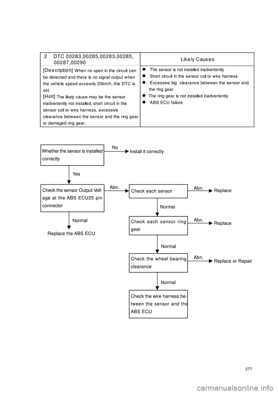
277Whether the sensor is installed
correctlyCheck the sensor Output Volt-
age at the ABS ECU25 pin
connector Check each sensorCheck each sensor ringgearCheck the wheel bearing
clearance Check the wire harness be-
tween the sensor and the
ABS ECUNo
Install it correctly
Replace the ABS ECUAbn.
Abn.
Abn.
Abn. Ye s
Normal Normal
Normal
NormalReplace
Replace
Replace or Repair 2 DTC 00283,00285,00283,00285,
00287,00290Like ly Caus e s
[De s cription]
When no open in the circuit can
be detected and there is no signal output when
the vehicle speed exceeds 20km/h, this DTC is
set.
[H int]
The likely c ause ma y be the se nsor
ina dvertently not insta lle d, short c ircuit in the
sensor coil or wire harness, excessive
clearance between the sensor and the ring gear
or dama ged ring ge a r.�z
T h e s e n s o r is n o t in s t a lle d in a d v e r t e n t ly
�z
Short c irc uit in the se nsor c oil or w ire ha rne ss
�z
Excessive big clearance between the sensor and
the ring gea r
�z
The ring gea r is not insta lle d ina dverte ntly
�z
ABS ECU failure
Page 285 of 392

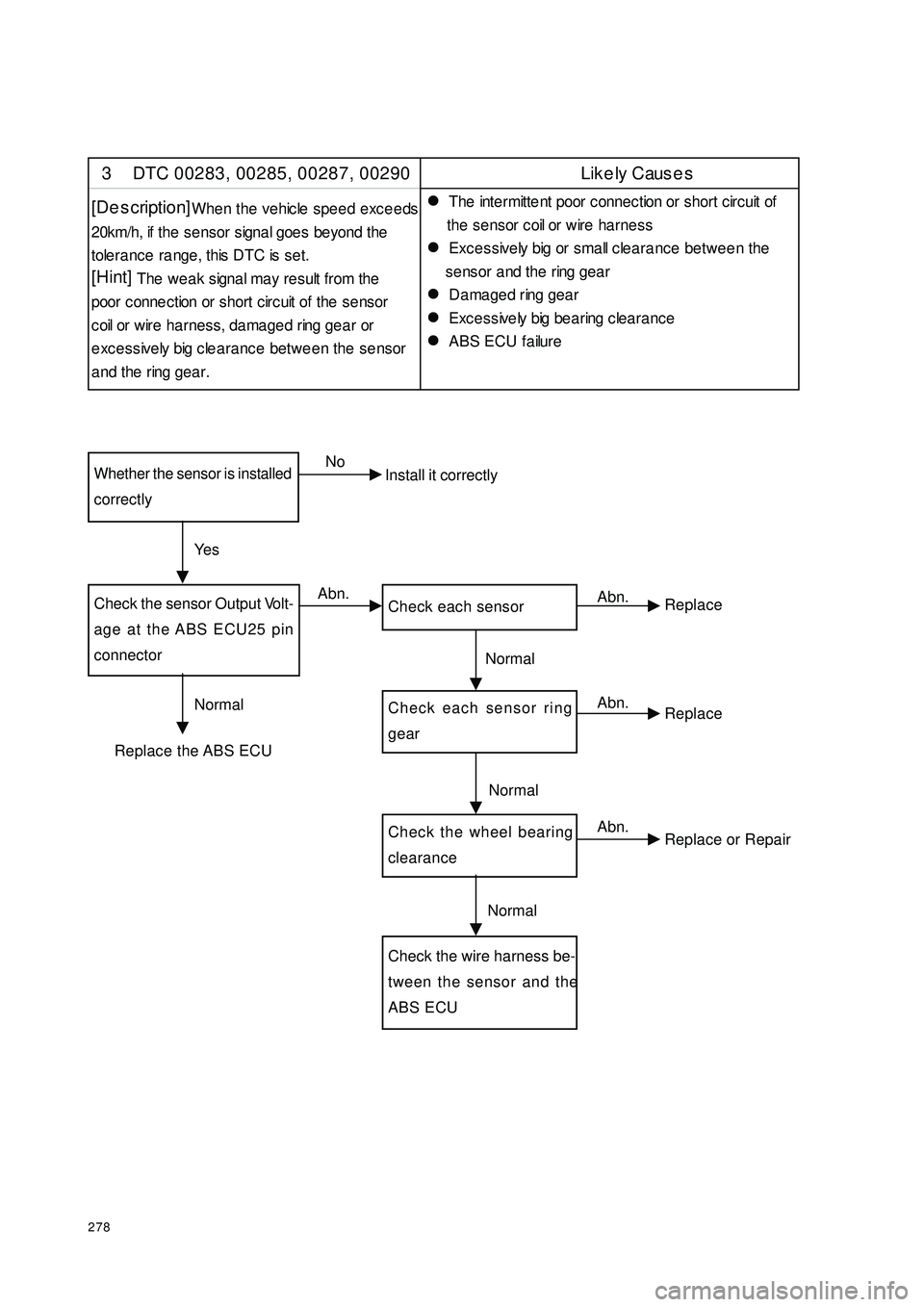
278Whether the sensor is installedcorrectlyCheck the sensor Output Volt-
age at the ABS ECU25 pin
connector Check each sensorCheck each sensor ringgearCheck the wheel bearing
clearance Check the wire harness be-
tween the sensor and the
ABS ECUNo
Install it correctly
Replace the ABS ECUAbn.
Abn.
Abn.
Abn. Ye s
Normal Normal
Normal
NormalReplace
Replace
Replace or Repair 3 DTC 00283, 00285, 00287, 00290 Likely Cause s
[De s cription]
When the vehicle speed exceeds
20km/h, if the se nsor signa l goe s be yond the
tolerance range, this DTC is set.
[Hint]
The we ak signa l ma y re sult from the
poor c onne c tion or short c irc uit of the se nsor
c oil or wire ha rness, da ma ge d ring gea r or
excessively big clearance between the sensor
a nd the ring gea r.�z The inte rmitte nt poor connec tion or short circ uit of
the se nsor c oil or wire ha rne ss
�z Excessively big or small clearance between the
se nsor a nd the ring gea r
�z Da ma ge d ring gea r
�z Exc e ssive ly big be a ring c lea ra nc e
�z ABS ECU failure