Page 1134 of 3000
2GR-FE FUEL – FUEL INJECTORFU–13
FU
REMOVAL
1. DISCHARGE FUEL SYSTEM PRESSURE
HINT:
See page FU-1.
2. DISCONNECT CABLE FROM NEGATIVE BATTERY
TERMINAL
3. REMOVE NO. 1 ENGINE UNDER COVER
4. DRAIN ENGINE COOLANT (See page CO-6)
5. REMOVE FRONT WIPER ARM HEAD CAP (See page
WW-4)
6. REMOVE FRONT WIPER ARM RH (See page WW-4)
7. REMOVE FRONT WIPER ARM LH (See page WW-4)
8. REMOVE COWL TOP VENTILATOR LOUVER SUB-
ASSEMBLY (See page WW-4)
9. REMOVE WINDSHIELD WIPER MOTOR AND LINK
ASSEMBLY (See page WW-4)
10. REMOVE NO. 1 COWL TOP TO COWL BRACE INNER
(a) Remove the 2 bolts and the No. 1 cowl top to cowl
brace inner.
11. REMOVE COWL TOP PANEL SUB-ASSEMBLY
OUTER FRONT
(a) Remove the wire harness clamp.
(b) Disconnect the fuel pump resistor connector.
(c) Remove the 7 bolts and the cowl top panel outer
front.
12. REMOVE V-BANK COVER SUB-ASSEMBLY (See
page EM-28)
13. REMOVE AIR CLEANER CAP SUB-ASSEMBLY
(a) Disconnect the 3 vacuum hoses.
A162429
A162430
A135112E01
Page 1137 of 3000
FU–162GR-FE FUEL – FUEL INJECTOR
FU
(c) Remove the 6 injector vibration insulators from the
intake manifold.
(d) Pull out the fuel injectors from the fuel delivery pipe
sub-assembly.
(e) Remove the 6 O-rings from the fuel injectors.
INSPECTION
1. INSPECT FUEL INJECTOR ASSEMBLY
(a) Inspect the injector resistance.
(1) Using an ohmmeter, measure the resistance
between the terminals.
Standard resistance
If the resistance is not as specified, replace the
injector.
(b) Inspect the injection volume.
CAUTION:
This test involves high-pressure fuel and
electricity. Take every precaution regarding the
safe handling of both fuel and electricity.
Perform this test in a safe area, and avoid any
sparks or flames. Do not smoke.
A129472E01
A129473
A129475E02
A116182
Tester Connection Condition Specified Condition
1-2 always11.6 to 12.4
at 20C (68F)
Page 1143 of 3000

2GR-FE FUEL – FUEL PRESSURE PULSATION DAMPERFU–25
FU
REMOVAL
1. DISCHARGE FUEL SYSTEM PRESSURE
HINT:
See page FU-1.
2. DISCONNECT CABLE FROM NEGATIVE BATTERY
TERMINAL
3. REMOVE NO. 1 ENGINE UNDER COVER
4. DRAIN ENGINE COOLANT (See page CO-6)
5. REMOVE FRONT WIPER ARM HEAD CAP (See page
WW-4)
6. REMOVE FRONT WIPER ARM RH (See page WW-4)
7. REMOVE FRONT WIPER ARM LH (See page WW-4)
8. REMOVE COWL TOP VENTILATOR LOUVER SUB-
ASSEMBLY (See page WW-4)
9. REMOVE WINDSHIELD WIPER MOTOR AND LINK
ASSEMBLY (See page WW-4)
10. REMOVE NO. 1 COWL TOP TO COWL BRACE INNER
(See page FU-13)
11. REMOVE COWL TOP PANEL SUB-ASSEMBLY
OUTER FRONT (See page FU-13)
12. REMOVE V-BANK COVER SUB-ASSEMBLY (See
page EM-28)
13. REMOVE AIR CLEANER CAP SUB-ASSEMBLY (See
page FU-13)
14. REMOVE INTAKE AIR SURGE TANK ASSEMBLY
(See page FU-14)
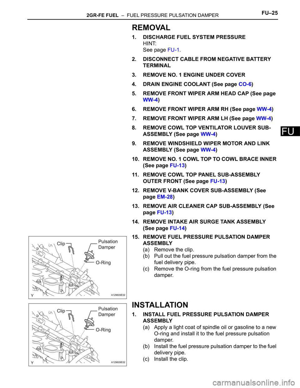
15. REMOVE FUEL PRESSURE PULSATION DAMPER
ASSEMBLY
(a) Remove the clip.
(b) Pull out the fuel pressure pulsation damper from the
fuel delivery pipe.
(c) Remove the O-ring from the fuel pressure pulsation
damper.
INSTALLATION
1. INSTALL FUEL PRESSURE PULSATION DAMPER
ASSEMBLY
(a) Apply a light coat of spindle oil or gasoline to a new
O-ring and install it to the fuel pressure pulsation
damper.
(b) Install the fuel pressure pulsation damper to the fuel
delivery pipe.
(c) Install the clip.
A129609E02
A129609E02
Page 1144 of 3000
FU–262GR-FE FUEL – FUEL PRESSURE PULSATION DAMPER
FU
2. INSTALL INTAKE AIR SURGE TANK ASSEMBLY (See
page FU-19)
3. INSTALL AIR CLEANER CAP SUB-ASSEMBLY (See
page FU-20)
4. ADD ENGINE COOLANT (See page CO-7)
5. CONNECT CABLE TO NEGATIVE BATTERY
TERMINAL
6. INSPECT FOR ENGINE COOLANT LEAK (See page
CO-1)
7. INSTALL NO. 1 ENGINE UNDER COVER
8. INSPECT FOR FUEL LEAK (See page FU-7)
9. INSTALL V-BANK COVER SUB-ASSEMBLY (See
page EM-63)
10. INSTALL COWL TOP PANEL SUB-ASSEMBLY
OUTER FRONT (See page FU-21)
11. INSTALL NO. 1 COWL TOP TO COWL BRACE INNER
(See page FU-21)
12. INSTALL WINDSHIELD WIPER MOTOR AND LINK
ASSEMBLY (See page WW-6)
13. INSTALL FRONT WIPER ARM LH (See page WW-6)
14. INSTALL FRONT WIPER ARM RH (See page WW-7)
Page 1145 of 3000
FU–302GR-FE FUEL – FUEL PUMP
FU
REMOVAL
1. DISCHARGE FUEL SYSTEM PRESSURE
(See page FU-1)
2. REMOVE CHARCOAL CANISTER PROTECTOR
(a) Remove the 6bolts and the charcoal canister
protector.
3. REMOVE REAR FLOOR NO. 2 CROSSMEMBER
BRACE LH (See page FU-41)
4. REMOVE FUEL TANK FILLER HOSE COVER (See
page FU-41)
5. REMOVE FUEL TANK ASSEMBLY (See page FU-41)
Page 1148 of 3000
FU–302GR-FE FUEL – FUEL PUMP
FU
REMOVAL
1. DISCHARGE FUEL SYSTEM PRESSURE
(See page FU-1)
2. REMOVE CHARCOAL CANISTER PROTECTOR
(a) Remove the 6bolts and the charcoal canister
protector.
3. REMOVE REAR FLOOR NO. 2 CROSSMEMBER
BRACE LH (See page FU-41)
4. REMOVE FUEL TANK FILLER HOSE COVER (See
page FU-41)
5. REMOVE FUEL TANK ASSEMBLY (See page FU-41)
Page 1151 of 3000

2GR-FE FUEL – FUEL PUMPFU–33
FU
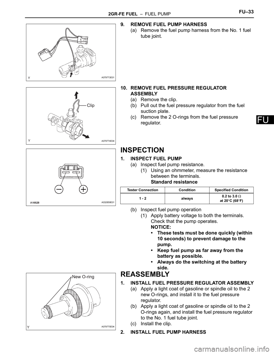
9. REMOVE FUEL PUMP HARNESS
(a) Remove the fuel pump harness from the No. 1 fuel
tube joint.
10. REMOVE FUEL PRESSURE REGULATOR
ASSEMBLY
(a) Remove the clip.
(b) Pull out the fuel pressure regulator from the fuel
suction plate.
(c) Remove the 2 O-rings from the fuel pressure
regulator.
INSPECTION
1. INSPECT FUEL PUMP
(a) Inspect fuel pump resistance.
(1) Using an ohmmeter, measure the resistance
between the terminals.
Standard resistance
(b) Inspect fuel pump operation
(1) Apply battery voltage to both the terminals.
Check that the pump operates.
NOTICE:
• These tests must be done quickly (within
10 seconds) to prevent damage to the
pump.
• Keep fuel pump as far away from the
battery as possible.
• Always do the switching at the battery
side.
REASSEMBLY
1. INSTALL FUEL PRESSURE REGULATOR ASSEMBLY
(a) Apply a light coat of gasoline or spindle oil to the 2
new O-rings, and install it to the fuel pressure
regulator.
(b) Apply a light coat of gasoline or spindle oil to the 2
O-rings again, and install the fuel pressure regulator
to the No. 1 fuel tube joint.
(c) Install the clip.
2. INSTALL FUEL PUMP HARNESS
A079773E01
A079774E04
A032859E01
Tester Connection Condition Specified Condition
1 - 2 always0.2 to 3.0
at 20
C (68F)
A079775E04
Page 1156 of 3000

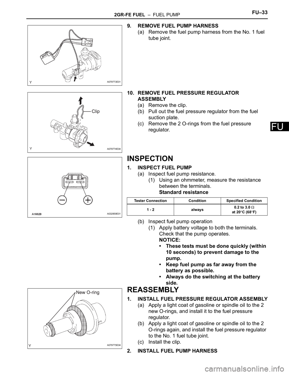
2GR-FE FUEL – FUEL PUMPFU–33
FU
9. REMOVE FUEL PUMP HARNESS
(a) Remove the fuel pump harness from the No. 1 fuel
tube joint.
10. REMOVE FUEL PRESSURE REGULATOR
ASSEMBLY
(a) Remove the clip.
(b) Pull out the fuel pressure regulator from the fuel
suction plate.
(c) Remove the 2 O-rings from the fuel pressure
regulator.
INSPECTION
1. INSPECT FUEL PUMP
(a) Inspect fuel pump resistance.
(1) Using an ohmmeter, measure the resistance
between the terminals.
Standard resistance
(b) Inspect fuel pump operation
(1) Apply battery voltage to both the terminals.
Check that the pump operates.
NOTICE:
• These tests must be done quickly (within
10 seconds) to prevent damage to the
pump.
• Keep fuel pump as far away from the
battery as possible.
• Always do the switching at the battery
side.
REASSEMBLY
1. INSTALL FUEL PRESSURE REGULATOR ASSEMBLY
(a) Apply a light coat of gasoline or spindle oil to the 2
new O-rings, and install it to the fuel pressure
regulator.
(b) Apply a light coat of gasoline or spindle oil to the 2
O-rings again, and install the fuel pressure regulator
to the No. 1 fuel tube joint.
(c) Install the clip.
2. INSTALL FUEL PUMP HARNESS
A079773E01
A079774E04
A032859E01
Tester Connection Condition Specified Condition
1 - 2 always0.2 to 3.0
at 20
C (68F)
A079775E04