Page 985 of 3000
EM–262GR-FE ENGINE MECHANICAL – ENGINE ASSEMBLY
EM
REMOVAL
1. DISCHARGE FUEL SYSTEM PRESSURE (See page
FU-13)
2. DISCHARGE REFRIGERANT FROM
REFRIGERATION SYSTEM (See page AC-172)
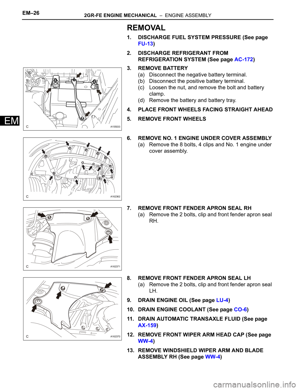
3. REMOVE BATTERY
(a) Disconnect the negative battery terminal.
(b) Disconnect the positive battery terminal.
(c) Loosen the nut, and remove the bolt and battery
clamp.
(d) Remove the battery and battery tray.
4. PLACE FRONT WHEELS FACING STRAIGHT AHEAD
5. REMOVE FRONT WHEELS
6. REMOVE NO. 1 ENGINE UNDER COVER ASSEMBLY
(a) Remove the 8 bolts, 4 clips and No. 1 engine under
cover assembly.
7. REMOVE FRONT FENDER APRON SEAL RH
(a) Remove the 2 bolts, clip and front fender apron seal
RH.
8. REMOVE FRONT FENDER APRON SEAL LH
(a) Remove the 2 bolts, clip and front fender apron seal
LH.
9. DRAIN ENGINE OIL (See page LU-4)
10. DRAIN ENGINE COOLANT (See page CO-6)
11. DRAIN AUTOMATIC TRANSAXLE FLUID (See page
AX-159)
12. REMOVE FRONT WIPER ARM HEAD CAP (See page
WW-4)
13. REMOVE WINDSHIELD WIPER ARM AND BLADE
ASSEMBLY RH (See page WW-4)
A155033
A162362
A162371
A162370
Page 1117 of 3000
2GR-FE FUEL – FUEL SYSTEMFU–7
FU
ON-VEHICLE INSPECTION
1. INSPECT FOR FUEL PUMP OPERATION AND FUEL
LEAK
(a) Check fuel pump operation.
(1) Connect the intelligent tester to the DLC3.
(2) Turn the engine switch on (IG) and push the
intelligent tester main switch on.
NOTICE:
Do not start the engine.
(3) Select the following menu items: DIAGNOSIS /
ENHANCED OBD II / ACTIVE TEST / FUEL
PUMP / SPD.
(4) Check for pressure in the fuel inlet tube from
the fuel line. Check that sound of fuel flowing in
the fuel tank can be heard. If no sound can be
heard, check the integration relay, fuel pump,
ECM and wiring connector.
(b) Check for fuel leaks (*1).
(1) Check that there are no fuel leaks anywhere on
the system after performing maintenance. If
there is a fuel leak, repair or replace parts as
necessary.
(c) Turn the engine switch off.
(d) Disconnect the intelligent tester from the DLC3.
2. CHECK FUEL PRESSURE
(a) Discharge the fuel system pressure (See page FU-
1).
(b) Using a voltmeter, measure the battery voltage.
Standard voltage:
11 to 14 V
(c) Disconnect the cable from the negative (-) battery
terminal.
(d) Disconnect the fuel hose from the fuel main tube
(See page FU-1).
Page 1118 of 3000
FU–82GR-FE FUEL – FUEL SYSTEM
FU
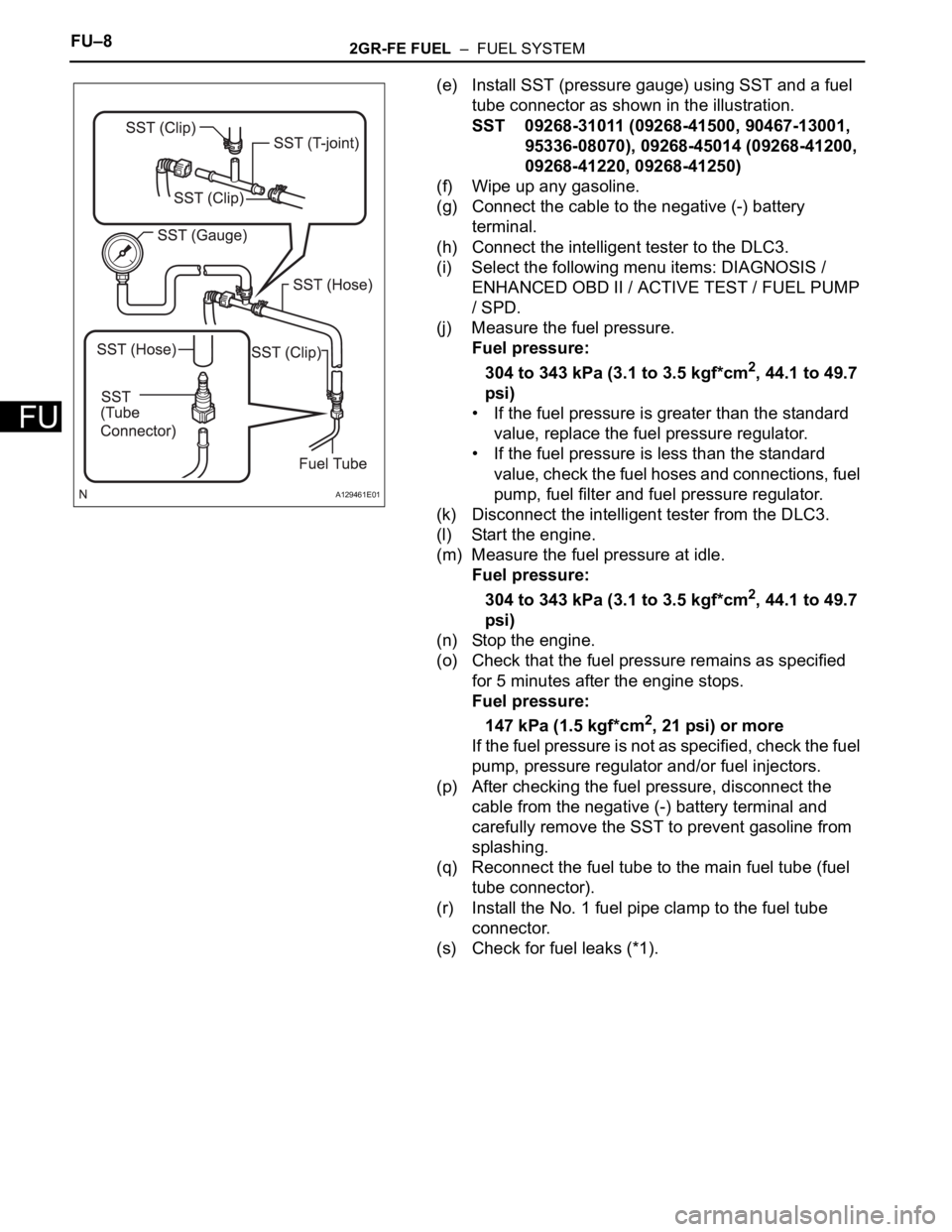
(e) Install SST (pressure gauge) using SST and a fuel
tube connector as shown in the illustration.
SST 09268-31011 (09268-41500, 90467-13001,
95336-08070), 09268-45014 (09268-41200,
09268-41220, 09268-41250)
(f) Wipe up any gasoline.
(g) Connect the cable to the negative (-) battery
terminal.
(h) Connect the intelligent tester to the DLC3.
(i) Select the following menu items: DIAGNOSIS /
ENHANCED OBD II / ACTIVE TEST / FUEL PUMP
/ SPD.
(j) Measure the fuel pressure.
Fuel pressure:
304 to 343 kPa (3.1 to 3.5 kgf*cm
2, 44.1 to 49.7
psi)
• If the fuel pressure is greater than the standard
value, replace the fuel pressure regulator.
• If the fuel pressure is less than the standard
value, check the fuel hoses and connections, fuel
pump, fuel filter and fuel pressure regulator.
(k) Disconnect the intelligent tester from the DLC3.
(l) Start the engine.
(m) Measure the fuel pressure at idle.
Fuel pressure:
304 to 343 kPa (3.1 to 3.5 kgf*cm
2, 44.1 to 49.7
psi)
(n) Stop the engine.
(o) Check that the fuel pressure remains as specified
for 5 minutes after the engine stops.
Fuel pressure:
147 kPa (1.5 kgf*cm
2, 21 psi) or more
If the fuel pressure is not as specified, check the fuel
pump, pressure regulator and/or fuel injectors.
(p) After checking the fuel pressure, disconnect the
cable from the negative (-) battery terminal and
carefully remove the SST to prevent gasoline from
splashing.
(q) Reconnect the fuel tube to the main fuel tube (fuel
tube connector).
(r) Install the No. 1 fuel pipe clamp to the fuel tube
connector.
(s) Check for fuel leaks (*1).
A129461E01
Page 1119 of 3000
2GR-FE FUEL – FUEL INJECTORFU–13
FU
REMOVAL
1. DISCHARGE FUEL SYSTEM PRESSURE
HINT:
See page FU-1.
2. DISCONNECT CABLE FROM NEGATIVE BATTERY
TERMINAL
3. REMOVE NO. 1 ENGINE UNDER COVER
4. DRAIN ENGINE COOLANT (See page CO-6)
5. REMOVE FRONT WIPER ARM HEAD CAP (See page
WW-4)
6. REMOVE FRONT WIPER ARM RH (See page WW-4)
7. REMOVE FRONT WIPER ARM LH (See page WW-4)
8. REMOVE COWL TOP VENTILATOR LOUVER SUB-
ASSEMBLY (See page WW-4)
9. REMOVE WINDSHIELD WIPER MOTOR AND LINK
ASSEMBLY (See page WW-4)
10. REMOVE NO. 1 COWL TOP TO COWL BRACE INNER
(a) Remove the 2 bolts and the No. 1 cowl top to cowl
brace inner.
11. REMOVE COWL TOP PANEL SUB-ASSEMBLY
OUTER FRONT
(a) Remove the wire harness clamp.
(b) Disconnect the fuel pump resistor connector.
(c) Remove the 7 bolts and the cowl top panel outer
front.
12. REMOVE V-BANK COVER SUB-ASSEMBLY (See
page EM-28)
13. REMOVE AIR CLEANER CAP SUB-ASSEMBLY
(a) Disconnect the 3 vacuum hoses.
A162429
A162430
A135112E01
Page 1122 of 3000
2GR-FE FUEL – FUEL SYSTEMFU–1
FU
FUEL SYSTEM
PRECAUTION
1. PRECAUTION
(a) Before inspecting and repairing the fuel system,
disconnect the cable from the negative (-) battery
terminal.
(b) Do not smoke or work near fire when handling the
fuel system.
(c) Keep gasoline away from rubber or leather parts.
2. DISCHARGE FUEL SYSTEM PRESSURE (*1)
CAUTION:
• Perform the following procedures to prevent fuel
from spilling out before removing any fuel system
parts.
• Pressure will still remain in the fuel line even after
performing the following procedures. When
disconnecting the fuel line, cover it with a shop
rag or a piece of cloth to prevent fuel from
spraying or coming out.
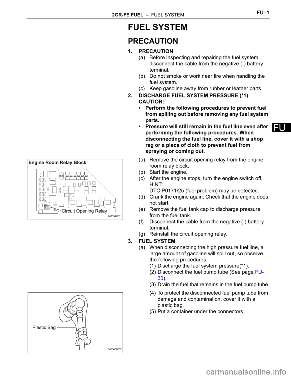
(a) Remove the circuit opening relay from the engine
room relay block.
(b) Start the engine.
(c) After the engine stops, turn the engine switch off.
HINT:
DTC P0171/25 (fuel problem) may be detected.
(d) Crank the engine again. Check that the engine does
not start.
(e) Remove the fuel tank cap to discharge pressure
from the fuel tank.
(f) Disconnect the cable from the negative (-) battery
terminal.
(g) Reinstall the circuit opening relay.
3. FUEL SYSTEM
(a) When disconnecting the high pressure fuel line, a
large amount of gasoline will spill out, so observe
the following procedures:
(1) Discharge the fuel system pressure(*1).
(2) Disconnect the fuel pump tube (See page FU-
30).
(3) Drain the fuel that remains in the fuel pump tube.
(4) To protect the disconnected fuel pump tube from
damage and contamination, cover it with a
plastic bag.
(5) Put a container under the connectors.
A075349E01
B000679E07
Page 1126 of 3000
2GR-FE FUEL – FUEL SYSTEMFU–7
FU
ON-VEHICLE INSPECTION
1. INSPECT FOR FUEL PUMP OPERATION AND FUEL
LEAK
(a) Check fuel pump operation.
(1) Connect the intelligent tester to the DLC3.
(2) Turn the engine switch on (IG) and push the
intelligent tester main switch on.
NOTICE:
Do not start the engine.
(3) Select the following menu items: DIAGNOSIS /
ENHANCED OBD II / ACTIVE TEST / FUEL
PUMP / SPD.
(4) Check for pressure in the fuel inlet tube from
the fuel line. Check that sound of fuel flowing in
the fuel tank can be heard. If no sound can be
heard, check the integration relay, fuel pump,
ECM and wiring connector.
(b) Check for fuel leaks (*1).
(1) Check that there are no fuel leaks anywhere on
the system after performing maintenance. If
there is a fuel leak, repair or replace parts as
necessary.
(c) Turn the engine switch off.
(d) Disconnect the intelligent tester from the DLC3.
2. CHECK FUEL PRESSURE
(a) Discharge the fuel system pressure (See page FU-
1).
(b) Using a voltmeter, measure the battery voltage.
Standard voltage:
11 to 14 V
(c) Disconnect the cable from the negative (-) battery
terminal.
(d) Disconnect the fuel hose from the fuel main tube
(See page FU-1).
Page 1127 of 3000
FU–82GR-FE FUEL – FUEL SYSTEM
FU
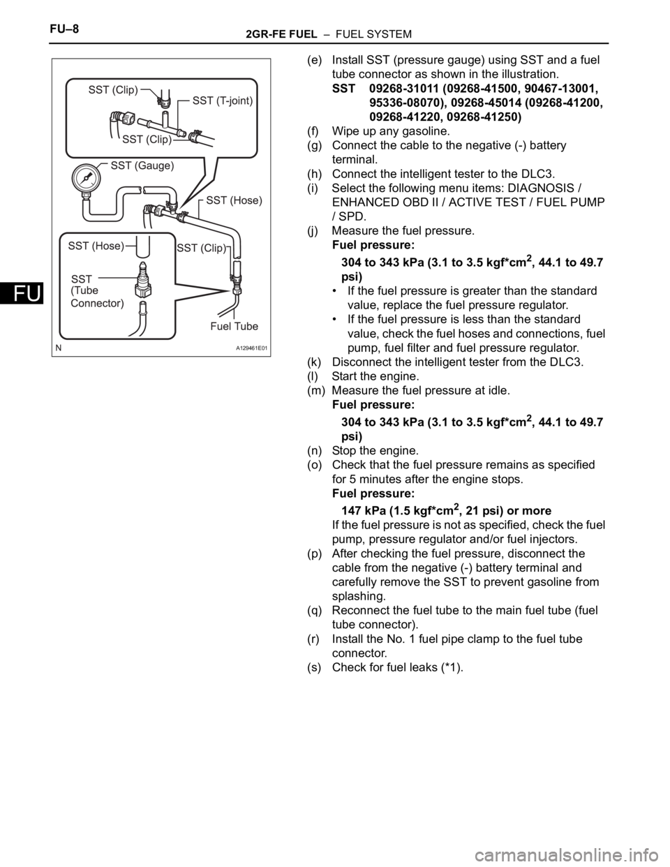
(e) Install SST (pressure gauge) using SST and a fuel
tube connector as shown in the illustration.
SST 09268-31011 (09268-41500, 90467-13001,
95336-08070), 09268-45014 (09268-41200,
09268-41220, 09268-41250)
(f) Wipe up any gasoline.
(g) Connect the cable to the negative (-) battery
terminal.
(h) Connect the intelligent tester to the DLC3.
(i) Select the following menu items: DIAGNOSIS /
ENHANCED OBD II / ACTIVE TEST / FUEL PUMP
/ SPD.
(j) Measure the fuel pressure.
Fuel pressure:
304 to 343 kPa (3.1 to 3.5 kgf*cm
2, 44.1 to 49.7
psi)
• If the fuel pressure is greater than the standard
value, replace the fuel pressure regulator.
• If the fuel pressure is less than the standard
value, check the fuel hoses and connections, fuel
pump, fuel filter and fuel pressure regulator.
(k) Disconnect the intelligent tester from the DLC3.
(l) Start the engine.
(m) Measure the fuel pressure at idle.
Fuel pressure:
304 to 343 kPa (3.1 to 3.5 kgf*cm
2, 44.1 to 49.7
psi)
(n) Stop the engine.
(o) Check that the fuel pressure remains as specified
for 5 minutes after the engine stops.
Fuel pressure:
147 kPa (1.5 kgf*cm
2, 21 psi) or more
If the fuel pressure is not as specified, check the fuel
pump, pressure regulator and/or fuel injectors.
(p) After checking the fuel pressure, disconnect the
cable from the negative (-) battery terminal and
carefully remove the SST to prevent gasoline from
splashing.
(q) Reconnect the fuel tube to the main fuel tube (fuel
tube connector).
(r) Install the No. 1 fuel pipe clamp to the fuel tube
connector.
(s) Check for fuel leaks (*1).
A129461E01
Page 1128 of 3000
FU–162GR-FE FUEL – FUEL INJECTOR
FU
(c) Remove the 6 injector vibration insulators from the
intake manifold.
(d) Pull out the fuel injectors from the fuel delivery pipe
sub-assembly.
(e) Remove the 6 O-rings from the fuel injectors.
INSPECTION
1. INSPECT FUEL INJECTOR ASSEMBLY
(a) Inspect the injector resistance.
(1) Using an ohmmeter, measure the resistance
between the terminals.
Standard resistance
If the resistance is not as specified, replace the
injector.
(b) Inspect the injection volume.
CAUTION:
This test involves high-pressure fuel and
electricity. Take every precaution regarding the
safe handling of both fuel and electricity.
Perform this test in a safe area, and avoid any
sparks or flames. Do not smoke.
A129472E01
A129473
A129475E02
A116182
Tester Connection Condition Specified Condition
1-2 always11.6 to 12.4
at 20C (68F)