2007 TOYOTA SIENNA fuel pressure
[x] Cancel search: fuel pressurePage 580 of 3000
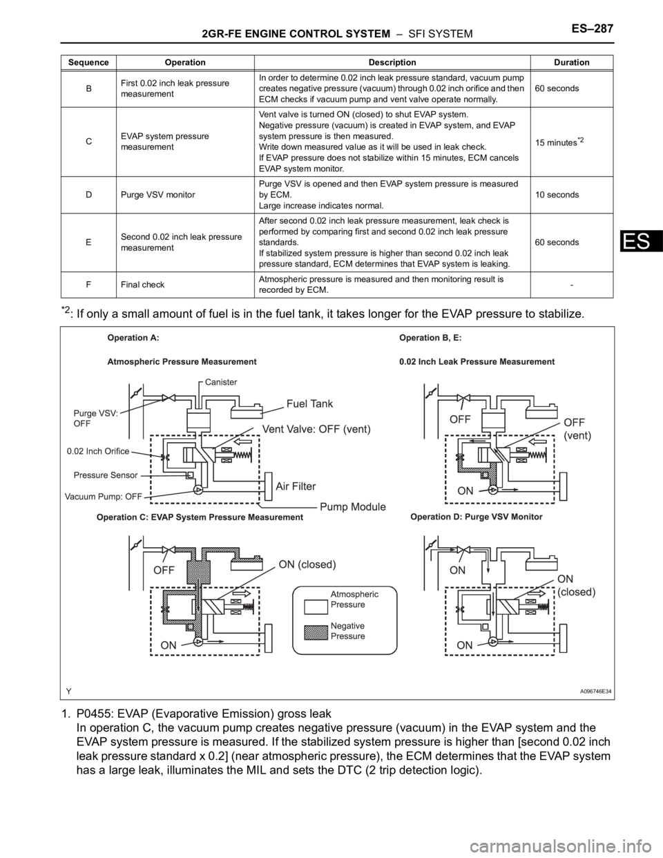
2GR-FE ENGINE CONTROL SYSTEM – SFI SYSTEMES–287
ES
*2: If only a small amount of fuel is in the fuel tank, it takes longer for the EVAP pressure to stabilize.
1. P0455: EVAP (Evaporative Emission) gross leak
In operation C, the vacuum pump creates negative pressure (vacuum) in the EVAP system and the
EVAP system pressure is measured. If the stabilized system pressure is higher than [second 0.02 inch
leak pressure standard x 0.2] (near atmospheric pressure), the ECM determines that the EVAP system
has a large leak, illuminates the MIL and sets the DTC (2 trip detection logic).
BFirst 0.02 inch leak pressure
measurementIn order to determine 0.02 inch leak pressure standard, vacuum pump
creates negative pressure (vacuum) through 0.02 inch orifice and then
ECM checks if vacuum pump and vent valve operate normally.60 seconds
CEVAP system pressure
measurementVent valve is turned ON (closed) to shut EVAP system.
Negative pressure (vacuum) is created in EVAP system, and EVAP
system pressure is then measured.
Write down measured value as it will be used in leak check.
If EVAP pressure does not stabilize within 15 minutes, ECM cancels
EVAP system monitor.15 minutes
*2
D Purge VSV monitorPurge VSV is opened and then EVAP system pressure is measured
by ECM.
Large increase indicates normal.10 seconds
ESecond 0.02 inch leak pressure
measurementAfter second 0.02 inch leak pressure measurement, leak check is
performed by comparing first and second 0.02 inch leak pressure
standards.
If stabilized system pressure is higher than second 0.02 inch leak
pressure standard, ECM determines that EVAP system is leaking.60 seconds
F Final checkAtmospheric pressure is measured and then monitoring result is
recorded by ECM.- Sequence Operation Description Duration
A096746E34
Page 598 of 3000
2GR-FE ENGINE CONTROL SYSTEM – SFI SYSTEMES–305
ES
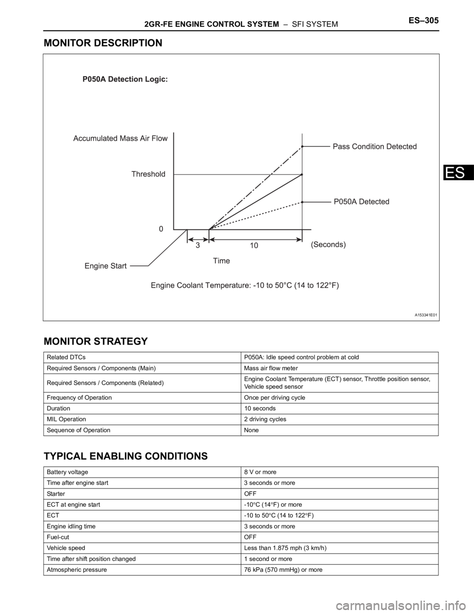
MONITOR DESCRIPTION
MONITOR STRATEGY
TYPICAL ENABLING CONDITIONS
Related DTCs P050A: Idle speed control problem at cold
Required Sensors / Components (Main) Mass air flow meter
Required Sensors / Components (Related)Engine Coolant Temperature (ECT) sensor, Throttle position sensor,
Vehicle speed sensor
Frequency of Operation Once per driving cycle
Duration 10 seconds
MIL Operation 2 driving cycles
Sequence of Operation None
Battery voltage 8 V or more
Time after engine start 3 seconds or more
Sta r t e r OF F
ECT at engine start -10
C (14F) or more
ECT -10 to 50
C (14 to 122F)
Engine idling time 3 seconds or more
Fuel-cut OFF
Vehicle speed Less than 1.875 mph (3 km/h)
Time after shift position changed 1 second or more
Atmospheric pressure 76 kPa (570 mmHg) or more
A153341E01
Page 604 of 3000
2GR-FE ENGINE CONTROL SYSTEM – SFI SYSTEMES–311
ES
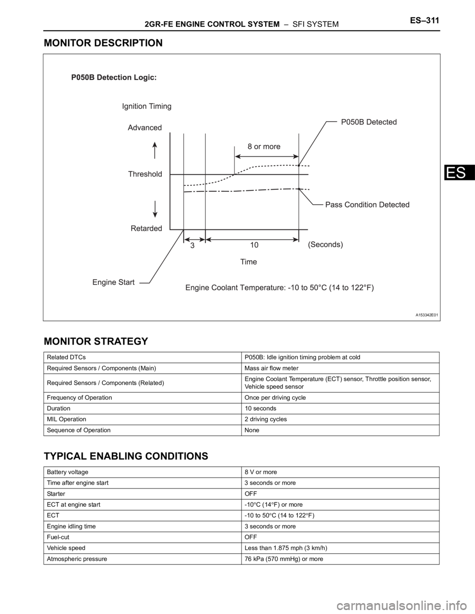
MONITOR DESCRIPTION
MONITOR STRATEGY
TYPICAL ENABLING CONDITIONS
Related DTCs P050B: Idle ignition timing problem at cold
Required Sensors / Components (Main) Mass air flow meter
Required Sensors / Components (Related)Engine Coolant Temperature (ECT) sensor, Throttle position sensor,
Vehicle speed sensor
Frequency of Operation Once per driving cycle
Duration 10 seconds
MIL Operation 2 driving cycles
Sequence of Operation None
Battery voltage 8 V or more
Time after engine start 3 seconds or more
Sta r t e r OF F
ECT at engine start -10
C (14F) or more
ECT -10 to 50
C (14 to 122F)
Engine idling time 3 seconds or more
Fuel-cut OFF
Vehicle speed Less than 1.875 mph (3 km/h)
Atmospheric pressure 76 kPa (570 mmHg) or more
A153342E01
Page 657 of 3000

ES–3642GR-FE ENGINE CONTROL SYSTEM – SFI SYSTEM
ES
HINT:
• DTCs P2195 and P2196 indicate malfunctions related to the bank 1 A/F sensor circuit.
• DTCs P2197 and P2198 indicate malfunctions related to the bank 2 A/F sensor circuit.
• Bank 1 refers to the bank that includes cylinder No. 1.
• Bank 2 refers to the bank that includes cylinder No. 2.
• When any of these DTCs are set, check the A/F sensor voltage output by selecting the following menu
items on the intelligent tester: DIAGNOSIS / ENHANCED OBDII / DATA LIST / PRIMARY / AFS B1S1.
• Short-term fuel trim values can also be read using the intelligent tester.
• The ECM regulates the voltages at the A1A+, A2A+, A1A- and A2A- terminals of the ECM to a
constant level. Therefore, the A/F sensor voltage output cannot be confirmed without using the
intelligent tester.
• If an A/F sensor malfunction is detected, the ECM sets a DTC.
MONITOR DESCRIPTION
Sensor voltage detection monitor
Under the air-fuel ratio feedback control, if the A/F sensor voltage output indicates rich or lean for a certain
period of time, the ECM determines that there is a malfunction in the A/F sensor. The ECM illuminates the
MIL and sets a DTC.
Example:
If the A/F sensor voltage output is less than 2.8 V (very rich condition) for 10 seconds, despite the HO2
sensor voltage output being less than 0.6 V, the ECM sets DTC P2196. Alternatively, if the A/F sensor
voltage output is more than 3.8 V (very lean condition) for 10 seconds, despite the HO2 sensor voltage
output being 0.15 V or more, DTC P2195 is set.
Sensor current detection monitor
A rich air-fuel mixture causes a low A/F sensor current, and a lean air-fuel mixture causes a high A/F
sensor current. Therefore, the sensor output becomes low during acceleration, and it becomes high
during deceleration with the throttle valve fully closed. The ECM monitors the A/F sensor current during
fuel-cut and detects any abnormal current values.
If the A/F sensor output is 3.6 mA or more for more than 3 seconds of cumulative time, the ECM interprets
this as a malfunction in the A/F sensor and sets DTC P2195 (high-side stuck). If the A/F sensor output is
1.0 mA or less for more than 3 seconds of cumulative time, the ECM sets DTC P2196 (low-side stuck).
DTC No. DTC Detection Condition Trouble Area
P2195
P2197Conditions (a) and (b) continue for 2 seconds or more
(2 trip detection logic):
(a) Air-Fuel Ratio (A/F) sensor voltage is more than 3.8
V
(b) Heated Oxygen (HO2) sensor voltage is 0.15 V or
more• Open or short in A/F sensor (bank 1, 2 sensor 1)
circuit
• A/F sensor (bank 1, 2 sensor 1)
• A/F sensor (bank 1, 2 sensor 1) heater
• A/F sensor heater relay
• A/F sensor heater and relay circuits
• Intake system
• Fuel pressure
• Injector
•ECM
P2195
P2197While fuel-cut operation is performed (during vehicle
deceleration), air-furl ratio (A/F) sensor current is 3.6
mA or more for 3 seconds (2 trip detection logic)• A/F sensor
•ECM
P2196
P2198Conditions (a) and (b) continue for 2 seconds or more
(2 trip detection logic):
(a) A/F sensor voltage is less than 2.8 V
(b) HO2 sensor voltage is less than 0.6 V• Open or short in A/F sensor (bank 1, 2 sensor 1)
circuit
• A/F sensor (bank 1, 2 sensor 1)
• A/F sensor (bank 1, 2 sensor 1) heater
• A/F sensor heater relay
• A/F sensor heater and relay circuits
• Intake system
• Fuel pressure
•Injector
•ECM
P2196
P2198While fuel-cut operation is performed (during vehicle
deceleration), air-furl ratio (A/F) sensor current is less
than 1.4 mA for 3 seconds (2 trip detection logic)• A/F sensor
•ECM
Page 659 of 3000

ES–3662GR-FE ENGINE CONTROL SYSTEM – SFI SYSTEM
ES
Sensor voltage detection monitor (Rich side malfunction P2196, P2198):
Sensor Current detection monitor P2195, P2196, P2197, P2198
TYPICAL MALFUNCTION THRESHOLDS
Sensor voltage detection monitor (Lean side malfunction P2195, P2197):
Sensor voltage detection monitor (Rich side malfunction P2196, P2198):
Sensor current detection monitor (High side malfunction P2195, P2197):
Sensor current detection monitor (Rich side malfunction P2196, P2198):
MONITOR RESULT
Refer to CHECKING MONITOR STATUS (See page ES-19).
Duration while all of the following conditions are met 2 seconds or more
Rear HO2 sensor voltage Less than 0.6 V
Time after engine start 30 seconds or more
A/F sensor status Activated
Fuel system status Closed-loop
Engine Running
Battery voltage 11 V or more
Atmospheric pressure 0.75 or more
Air-fuel ratio sensor status Activated
Engine coolant temperature 75
C (167F) or more
Continuous time of fuel-cut 3 to 10 seconds
A/F sensor voltage More than 3.8 V
A/F sensor voltage Less than 2.8 V
Air-fuel ratio sensor current during fuel cut 3.6 mA or more
Air-fuel ratio sensor current during fuel cut Less than 1.4 mA
Page 663 of 3000
ES–3702GR-FE ENGINE CONTROL SYSTEM – SFI SYSTEM
ES
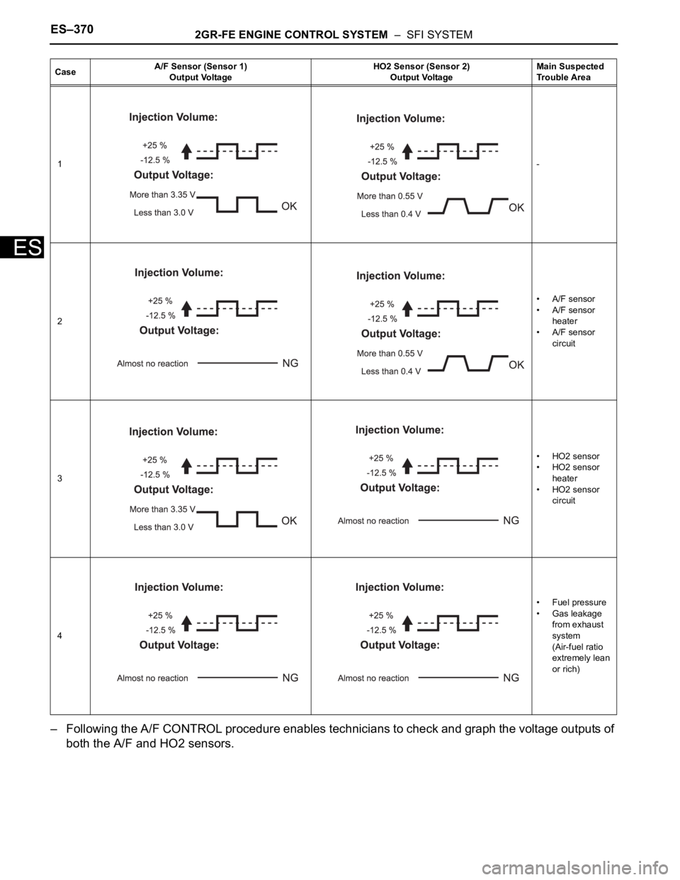
– Following the A/F CONTROL procedure enables technicians to check and graph the voltage outputs of
both the A/F and HO2 sensors.
CaseA/F Sensor (Sensor 1)
Output VoltageHO2 Sensor (Sensor 2)
Output VoltageMain Suspected
Trouble Area
1-
2• A/F sensor
• A/F sensor
heater
• A/F sensor
circuit
3• HO2 sensor
• HO2 sensor
heater
• HO2 sensor
circuit
4•Fuel pressure
• Gas leakage
from exhaust
system
(Air-fuel ratio
extremely lean
or rich)
Page 670 of 3000
2GR-FE ENGINE CONTROL SYSTEM – SFI SYSTEMES–377
ES
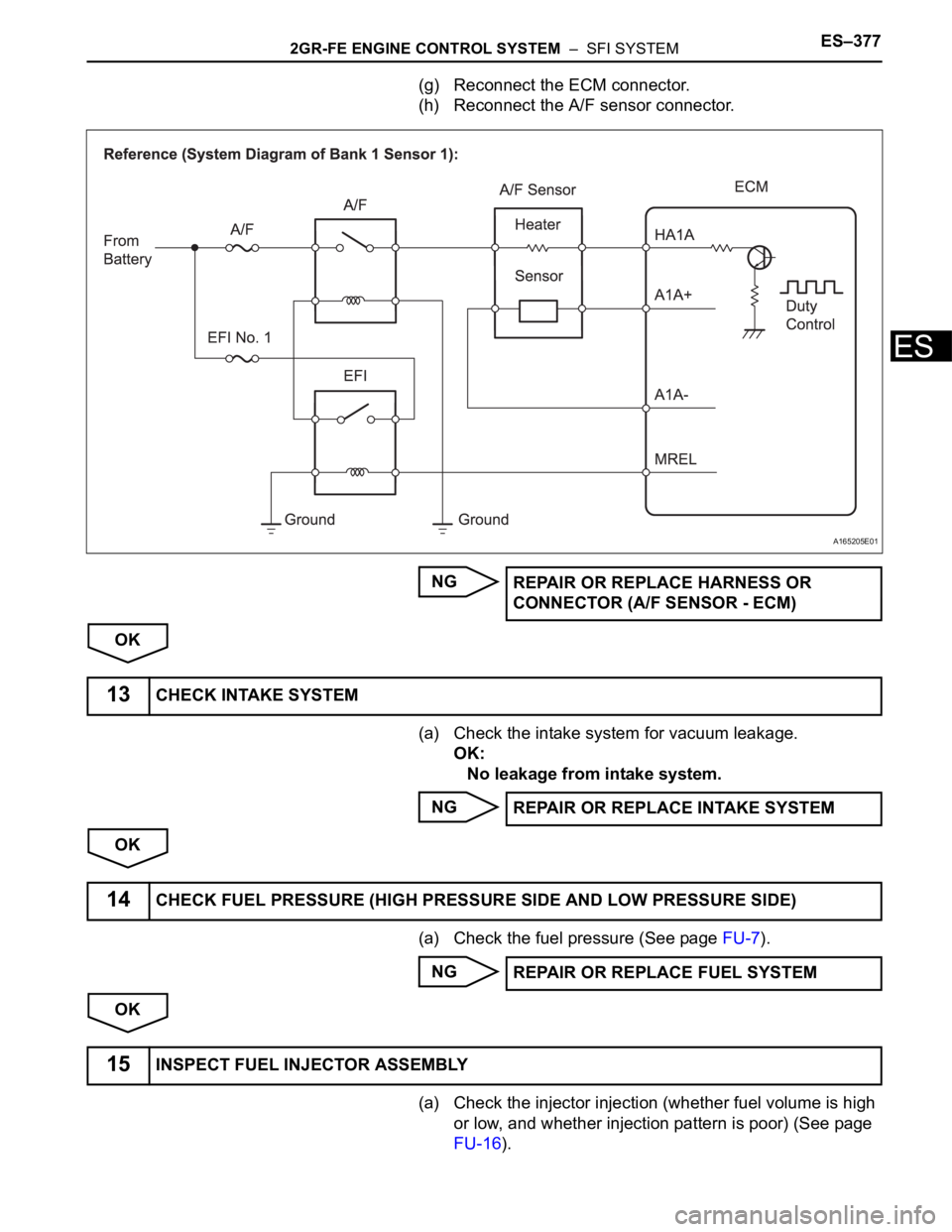
(g) Reconnect the ECM connector.
(h) Reconnect the A/F sensor connector.
NG
OK
(a) Check the intake system for vacuum leakage.
OK:
No leakage from intake system.
NG
OK
(a) Check the fuel pressure (See page FU-7).
NG
OK
(a) Check the injector injection (whether fuel volume is high
or low, and whether injection pattern is poor) (See page
FU-16).
A165205E01
REPAIR OR REPLACE HARNESS OR
CONNECTOR (A/F SENSOR - ECM)
13CHECK INTAKE SYSTEM
REPAIR OR REPLACE INTAKE SYSTEM
14CHECK FUEL PRESSURE (HIGH PRESSURE SIDE AND LOW PRESSURE SIDE)
REPAIR OR REPLACE FUEL SYSTEM
15INSPECT FUEL INJECTOR ASSEMBLY
Page 677 of 3000
ES–3842GR-FE ENGINE CONTROL SYSTEM – SFI SYSTEM
ES– Following the A/F CONTROL procedure enables technicians to check and graph the voltage outputs of
both the A/F and HO2 sensors.
– To display the graph, select the following menu items on the tester: DIAGNOSIS / ENHANCED OBD II
/ ACTIVE TEST / A/F CONTROL / USER DATA / AFS B1S1 and O2S B1S2 or AFS B2S1 and O2S
B2S2. Press the YES button and then the ENTER button. Then press the F4 button.
HINT:
• Read freeze frame data using the intelligent tester. The ECM records vehicle and driving condition
information as freeze frame data the moment a DTC is stored. When troubleshooting, freeze frame
data can be helpful in determining whether the vehicle was running or stopped, whether the engine
was warmed up or not, whether the air-fuel ratio was lean or rich, as well as other data recorded at
the time of a malfunction.
• A low A/F sensor voltage could be caused by a rich air-fuel mixture. Check for conditions that would
cause the engine to run rich.
• A high A/F sensor voltage could be caused by a lean air-fuel mixture. Check for conditions that
would cause the engine to run lean.
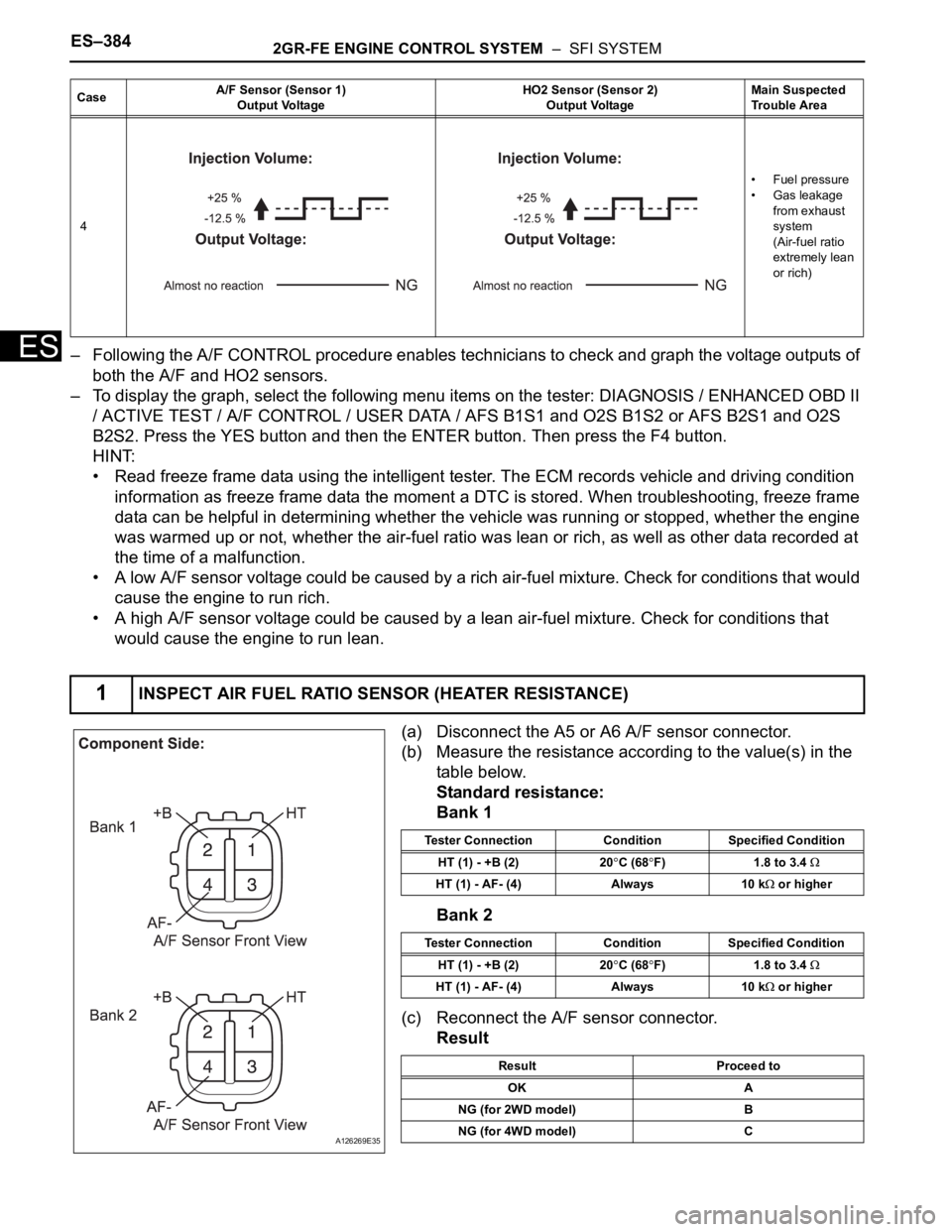
(a) Disconnect the A5 or A6 A/F sensor connector.
(b) Measure the resistance according to the value(s) in the
table below.
Standard resistance:
Bank 1
Bank 2
(c) Reconnect the A/F sensor connector.
Result
4•Fuel pressure
• Gas leakage
from exhaust
system
(Air-fuel ratio
extremely lean
or rich)
1INSPECT AIR FUEL RATIO SENSOR (HEATER RESISTANCE)
CaseA/F Sensor (Sensor 1)
Output VoltageHO2 Sensor (Sensor 2)
Output VoltageMain Suspected
Trouble Area
A126269E35
Tester Connection Condition Specified Condition
HT (1) - +B (2) 20
C (68F) 1.8 to 3.4
HT (1) - AF- (4) Always 10 k or higher
Tester Connection Condition Specified Condition
HT (1) - +B (2) 20
C (68F) 1.8 to 3.4
HT (1) - AF- (4) Always 10 k or higher
Result Proceed to
OK A
NG (for 2WD model) B
NG (for 4WD model) C