Page 1809 of 3000
AX–16U151F AUTOMATIC TRANSAXLE – AUTOMATIC TRANSAXLE SYSTEM
AX
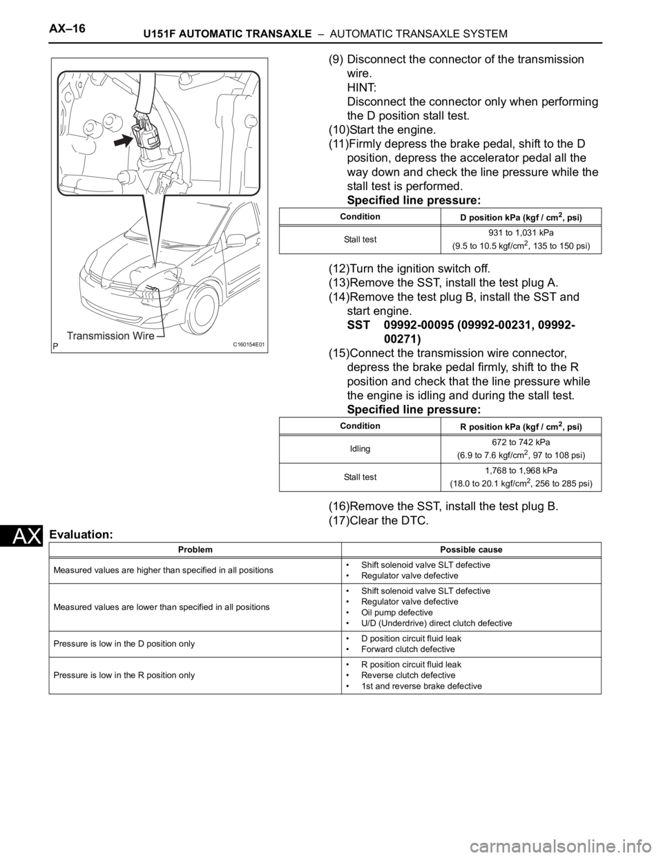
(9) Disconnect the connector of the transmission
wire.
HINT:
Disconnect the connector only when performing
the D position stall test.
(10)Start the engine.
(11)Firmly depress the brake pedal, shift to the D
position, depress the accelerator pedal all the
way down and check the line pressure while the
stall test is performed.
Specified line pressure:
(12)Turn the ignition switch off.
(13)Remove the SST, install the test plug A.
(14)Remove the test plug B, install the SST and
start engine.
SST 09992-00095 (09992-00231, 09992-
00271)
(15)Connect the transmission wire connector,
depress the brake pedal firmly, shift to the R
position and check that the line pressure while
the engine is idling and during the stall test.
Specified line pressure:
(16)Remove the SST, install the test plug B.
(17)Clear the DTC.
Evaluation:
C160154E01
Condition
D position kPa (kgf / cm2, psi)
Stall test931 to 1,031 kPa
(9.5 to 10.5 kgf/cm
2, 135 to 150 psi)
Condition
R position kPa (kgf / cm
2, psi)
Idling672 to 742 kPa
(6.9 to 7.6 kgf/cm
2, 97 to 108 psi)
Stall test1,768 to 1,968 kPa
(18.0 to 20.1 kgf/cm
2, 256 to 285 psi)
Problem Possible cause
Measured values are higher than specified in all positions• Shift solenoid valve SLT defective
• Regulator valve defective
Measured values are lower than specified in all positions• Shift solenoid valve SLT defective
• Regulator valve defective
• Oil pump defective
• U/D (Underdrive) direct clutch defective
Pressure is low in the D position only• D position circuit fluid leak
• Forward clutch defective
Pressure is low in the R position only• R position circuit fluid leak
• Reverse clutch defective
• 1st and reverse brake defective
Page 1817 of 3000
U151F AUTOMATIC TRANSAXLE – TRANSMISSION WIREAX–131
AX
REMOVAL
1. DISCONNECT CABLE FROM NEGATIVE BATTERY
TERMINAL
2. REMOVE ENGINE UNDER COVER NO.1
3. DRAIN AUTOMATIC TRANSAXLE FLUID
(a) Remove the drain plug and gasket, and drain the
AT F.
(b) Install a new gasket and the drain plug.
Torque: 49 N*m (500 kgf*cm, 36 ft.*lbf)
4. REMOVE AUTOMATIC TRANSAXLE OIL PAN SUB-
ASSEMBLY
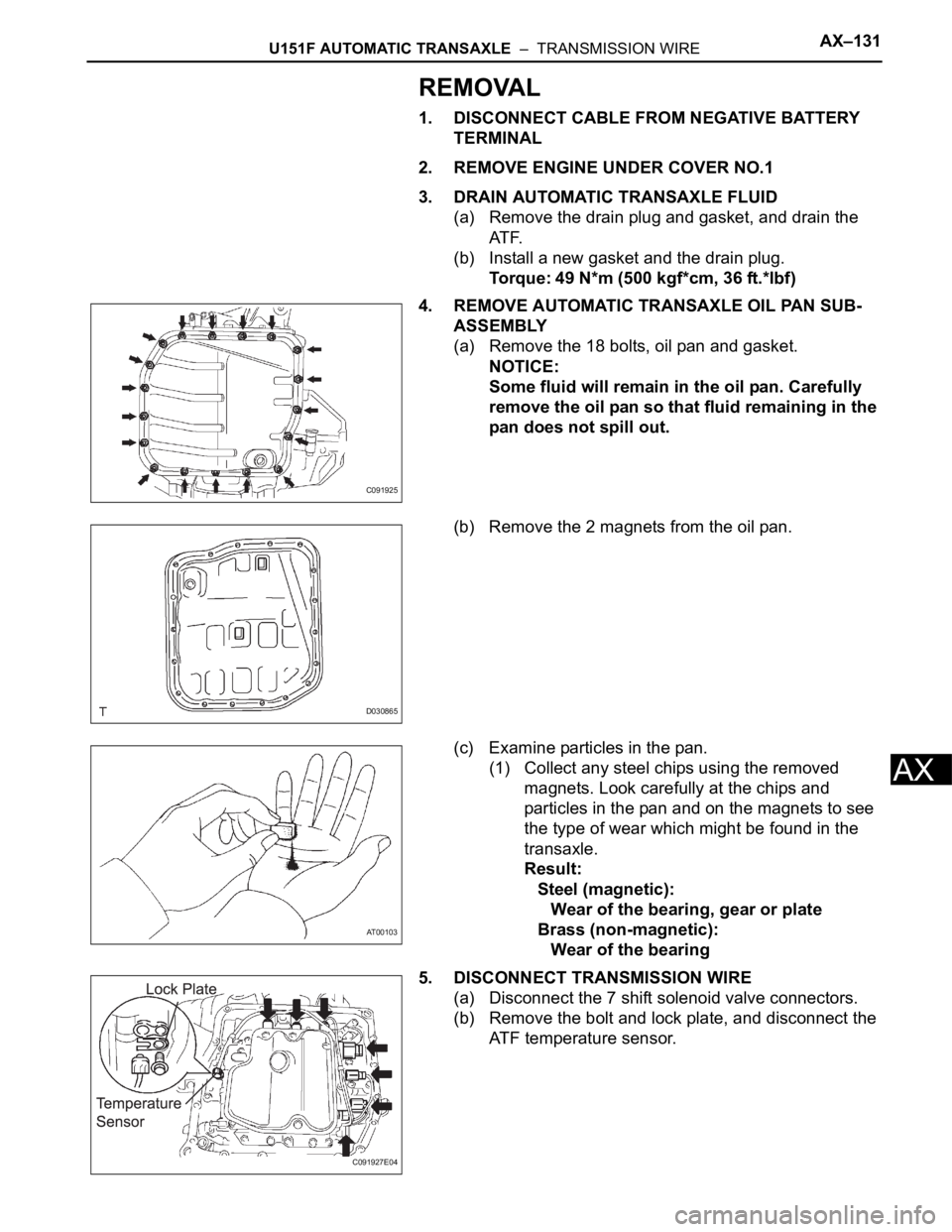
(a) Remove the 18 bolts, oil pan and gasket.
NOTICE:
Some fluid will remain in the oil pan. Carefully
remove the oil pan so that fluid remaining in the
pan does not spill out.
(b) Remove the 2 magnets from the oil pan.
(c) Examine particles in the pan.
(1) Collect any steel chips using the removed
magnets. Look carefully at the chips and
particles in the pan and on the magnets to see
the type of wear which might be found in the
transaxle.
Result:
Steel (magnetic):
Wear of the bearing, gear or plate
Brass (non-magnetic):
Wear of the bearing
5. DISCONNECT TRANSMISSION WIRE
(a) Disconnect the 7 shift solenoid valve connectors.
(b) Remove the bolt and lock plate, and disconnect the
ATF temperature sensor.
C091925
D030865
AT00103
C091927E04
Page 1819 of 3000
U151F AUTOMATIC TRANSAXLE – TRANSMISSION WIREAX–133
AX
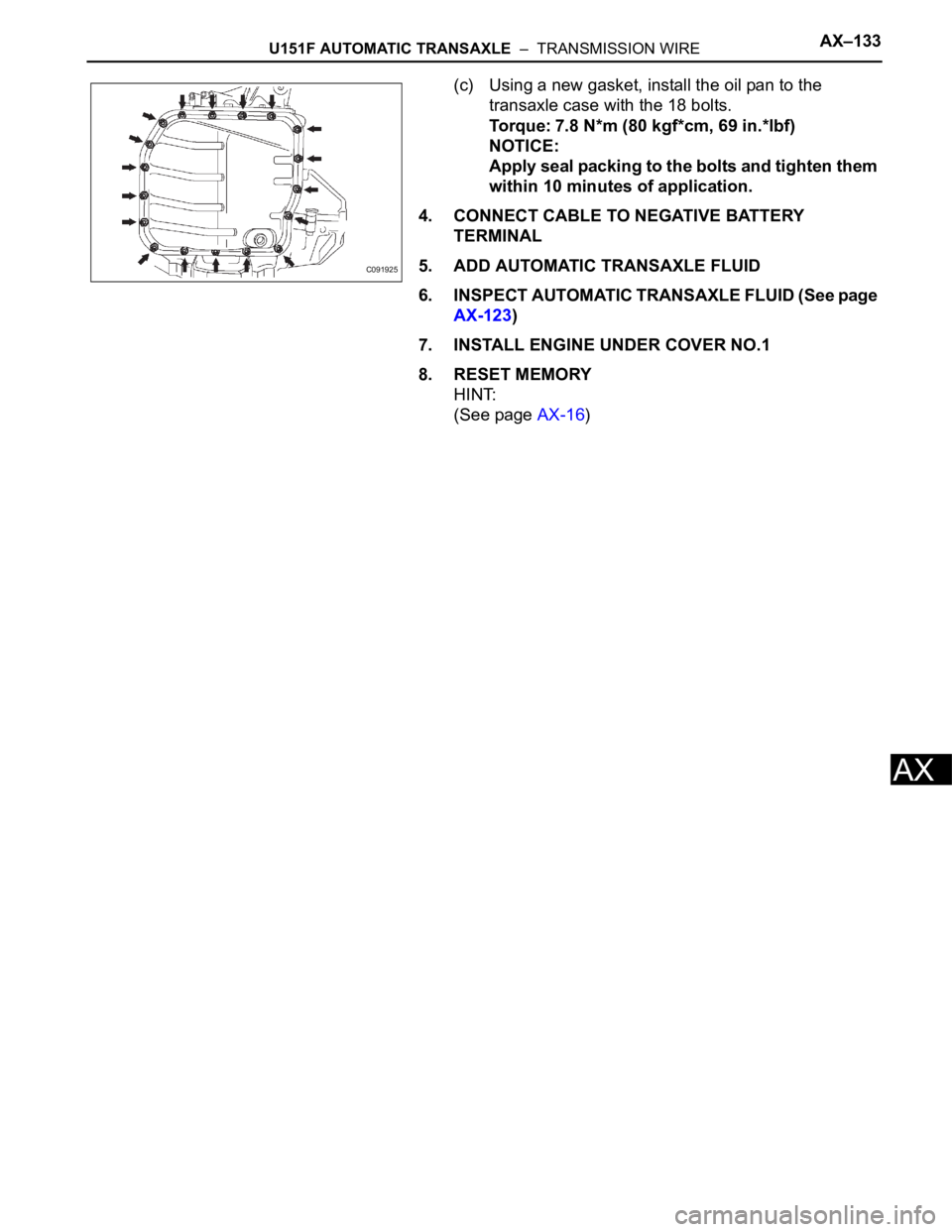
(c) Using a new gasket, install the oil pan to the
transaxle case with the 18 bolts.
Torque: 7.8 N*m (80 kgf*cm, 69 in.*lbf)
NOTICE:
Apply seal packing to the bolts and tighten them
within 10 minutes of application.
4. CONNECT CABLE TO NEGATIVE BATTERY
TERMINAL
5. ADD AUTOMATIC TRANSAXLE FLUID
6. INSPECT AUTOMATIC TRANSAXLE FLUID (See page
AX-123)
7. INSTALL ENGINE UNDER COVER NO.1
8. RESET MEMORY
HINT:
(See page AX-16)
C091925
Page 1822 of 3000
AX–136U151F AUTOMATIC TRANSAXLE – VALVE BODY ASSEMBLY
AX
REMOVAL
1. REMOVE ENGINE UNDER COVER NO.1
2. DISCONNECT CABLE FROM NEGATIVE BATTERY
TERMINAL
3. DRAIN AUTOMATIC TRANSAXLE FLUID (See page
AX-131)
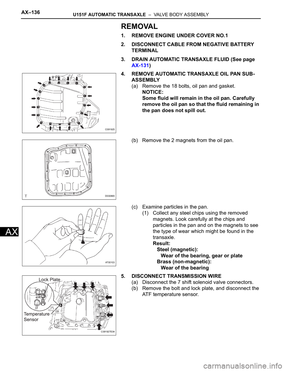
4. REMOVE AUTOMATIC TRANSAXLE OIL PAN SUB-
ASSEMBLY
(a) Remove the 18 bolts, oil pan and gasket.
NOTICE:
Some fluid will remain in the oil pan. Carefully
remove the oil pan so that the fluid remaining in
the pan does not spill out.
(b) Remove the 2 magnets from the oil pan.
(c) Examine particles in the pan.
(1) Collect any steel chips using the removed
magnets. Look carefully at the chips and
particles in the pan and on the magnets to see
the type of wear which might be found in the
transaxle.
Result:
Steel (magnetic):
Wear of the bearing, gear or plate
Brass (non-magnetic):
Wear of the bearing
5. DISCONNECT TRANSMISSION WIRE
(a) Disconnect the 7 shift solenoid valve connectors.
(b) Remove the bolt and lock plate, and disconnect the
ATF temperature sensor.
C091925
D030865
AT00103
C091927E04
Page 1823 of 3000
U151F AUTOMATIC TRANSAXLE – VALVE BODY ASSEMBLYAX–137
AX
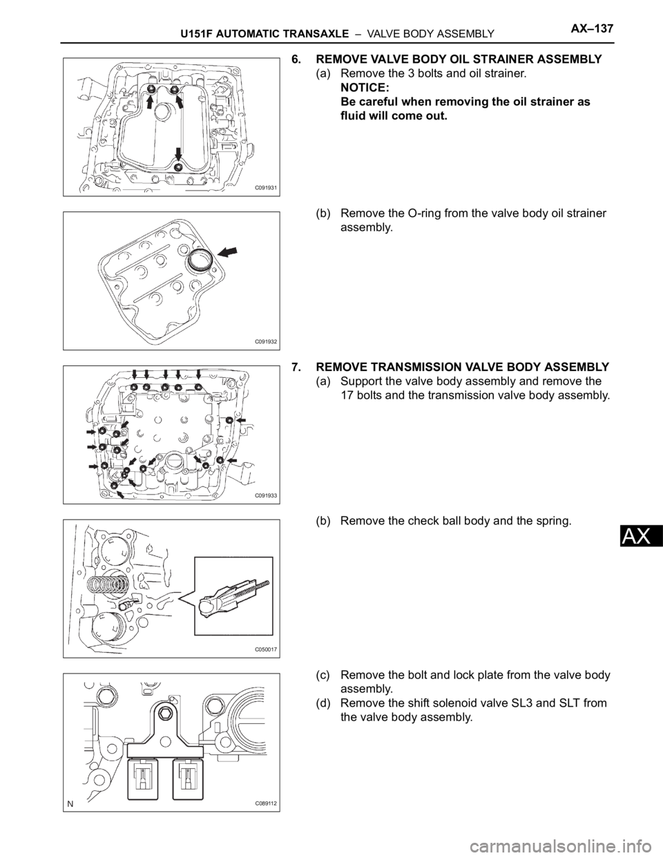
6. REMOVE VALVE BODY OIL STRAINER ASSEMBLY
(a) Remove the 3 bolts and oil strainer.
NOTICE:
Be careful when removing the oil strainer as
fluid will come out.
(b) Remove the O-ring from the valve body oil strainer
assembly.
7. REMOVE TRANSMISSION VALVE BODY ASSEMBLY
(a) Support the valve body assembly and remove the
17 bolts and the transmission valve body assembly.
(b) Remove the check ball body and the spring.
(c) Remove the bolt and lock plate from the valve body
assembly.
(d) Remove the shift solenoid valve SL3 and SLT from
the valve body assembly.
C091931
C091932
C091933
C050017
C089112
Page 1827 of 3000
U151F AUTOMATIC TRANSAXLE – VALVE BODY ASSEMBLYAX–141
AX
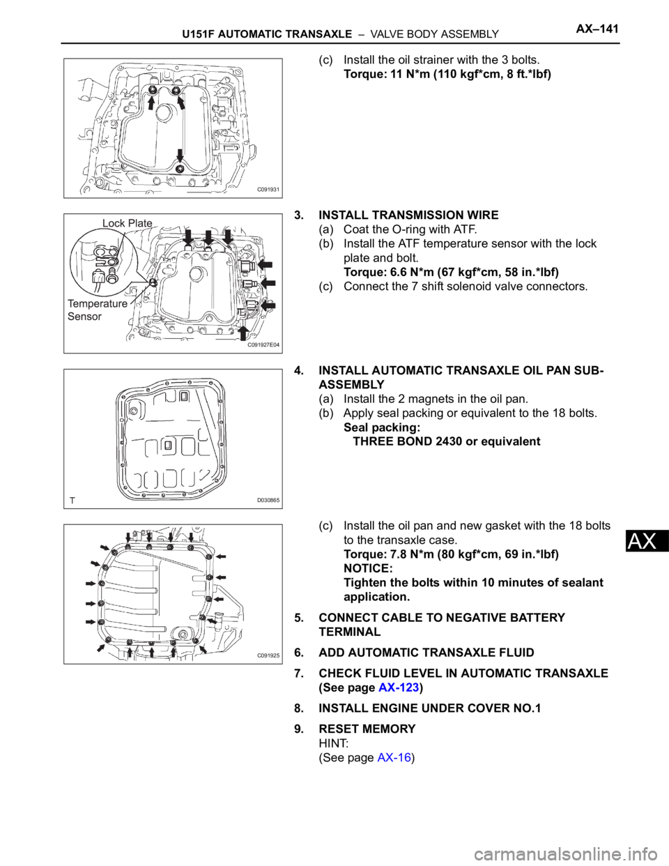
(c) Install the oil strainer with the 3 bolts.
Torque: 11 N*m (110 kgf*cm, 8 ft.*lbf)
3. INSTALL TRANSMISSION WIRE
(a) Coat the O-ring with ATF.
(b) Install the ATF temperature sensor with the lock
plate and bolt.
Torque: 6.6 N*m (67 kgf*cm, 58 in.*lbf)
(c) Connect the 7 shift solenoid valve connectors.
4. INSTALL AUTOMATIC TRANSAXLE OIL PAN SUB-
ASSEMBLY
(a) Install the 2 magnets in the oil pan.
(b) Apply seal packing or equivalent to the 18 bolts.
Seal packing:
THREE BOND 2430 or equivalent
(c) Install the oil pan and new gasket with the 18 bolts
to the transaxle case.
Torque: 7.8 N*m (80 kgf*cm, 69 in.*lbf)
NOTICE:
Tighten the bolts within 10 minutes of sealant
application.
5. CONNECT CABLE TO NEGATIVE BATTERY
TERMINAL
6. ADD AUTOMATIC TRANSAXLE FLUID
7. CHECK FLUID LEVEL IN AUTOMATIC TRANSAXLE
(See page AX-123)
8. INSTALL ENGINE UNDER COVER NO.1
9. RESET MEMORY
HINT:
(See page AX-16)
C091931
C091927E04
D030865
C091925