Page 118 of 3000
DRIVE SHAFT – FRONT DRIVE SHAFTDS–13
DS
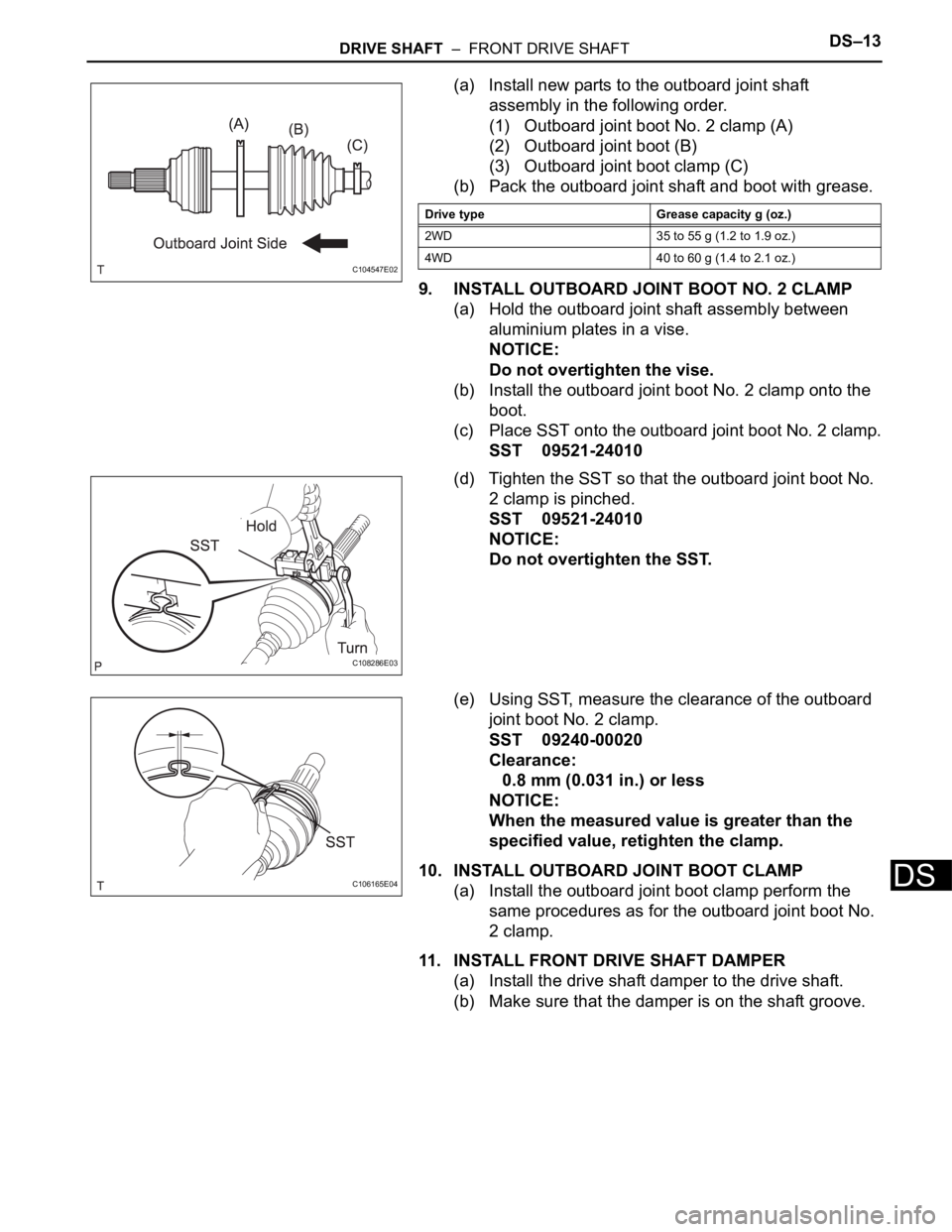
(a) Install new parts to the outboard joint shaft
assembly in the following order.
(1) Outboard joint boot No. 2 clamp (A)
(2) Outboard joint boot (B)
(3) Outboard joint boot clamp (C)
(b) Pack the outboard joint shaft and boot with grease.
9. INSTALL OUTBOARD JOINT BOOT NO. 2 CLAMP
(a) Hold the outboard joint shaft assembly between
aluminium plates in a vise.
NOTICE:
Do not overtighten the vise.
(b) Install the outboard joint boot No. 2 clamp onto the
boot.
(c) Place SST onto the outboard joint boot No. 2 clamp.
SST 09521-24010
(d) Tighten the SST so that the outboard joint boot No.
2 clamp is pinched.
SST 09521-24010
NOTICE:
Do not overtighten the SST.
(e) Using SST, measure the clearance of the outboard
joint boot No. 2 clamp.
SST 09240-00020
Clearance:
0.8 mm (0.031 in.) or less
NOTICE:
When the measured value is greater than the
specified value, retighten the clamp.
10. INSTALL OUTBOARD JOINT BOOT CLAMP
(a) Install the outboard joint boot clamp perform the
same procedures as for the outboard joint boot No.
2 clamp.
11. INSTALL FRONT DRIVE SHAFT DAMPER
(a) Install the drive shaft damper to the drive shaft.
(b) Make sure that the damper is on the shaft groove.
C104547E02
Drive type Grease capacity g (oz.)
2WD 35 to 55 g (1.2 to 1.9 oz.)
4WD 40 to 60 g (1.4 to 2.1 oz.)
C108286E03
C106165E04
Page 119 of 3000
DS–14DRIVE SHAFT – FRONT DRIVE SHAFT
DS
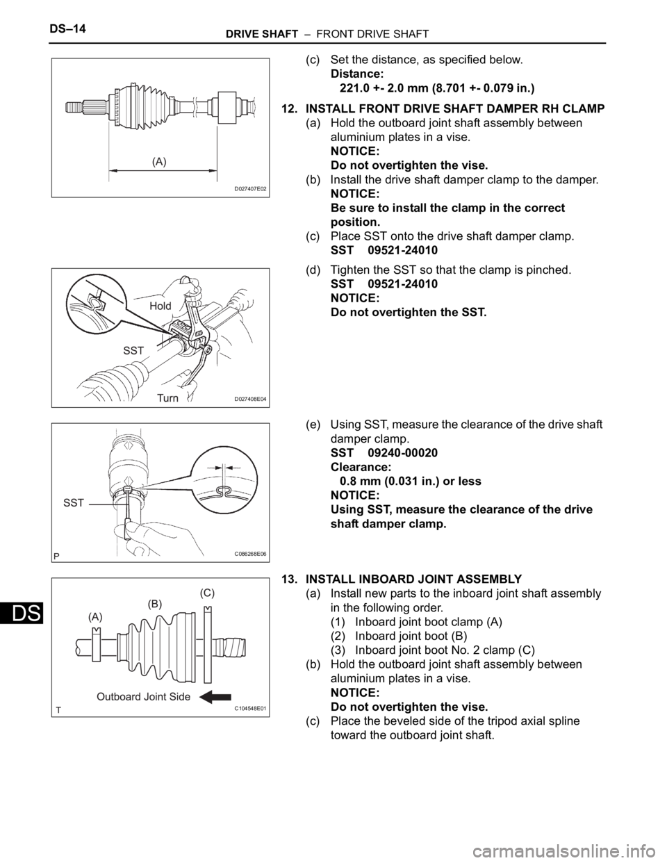
(c) Set the distance, as specified below.
Distance:
221.0 +- 2.0 mm (8.701 +- 0.079 in.)
12. INSTALL FRONT DRIVE SHAFT DAMPER RH CLAMP
(a) Hold the outboard joint shaft assembly between
aluminium plates in a vise.
NOTICE:
Do not overtighten the vise.
(b) Install the drive shaft damper clamp to the damper.
NOTICE:
Be sure to install the clamp in the correct
position.
(c) Place SST onto the drive shaft damper clamp.
SST 09521-24010
(d) Tighten the SST so that the clamp is pinched.
SST 09521-24010
NOTICE:
Do not overtighten the SST.
(e) Using SST, measure the clearance of the drive shaft
damper clamp.
SST 09240-00020
Clearance:
0.8 mm (0.031 in.) or less
NOTICE:
Using SST, measure the clearance of the drive
shaft damper clamp.
13. INSTALL INBOARD JOINT ASSEMBLY
(a) Install new parts to the inboard joint shaft assembly
in the following order.
(1) Inboard joint boot clamp (A)
(2) Inboard joint boot (B)
(3) Inboard joint boot No. 2 clamp (C)
(b) Hold the outboard joint shaft assembly between
aluminium plates in a vise.
NOTICE:
Do not overtighten the vise.
(c) Place the beveled side of the tripod axial spline
toward the outboard joint shaft.
D027407E02
D027408E04
C086268E06
C104548E01
Page 120 of 3000
DRIVE SHAFT – FRONT DRIVE SHAFTDS–15
DS
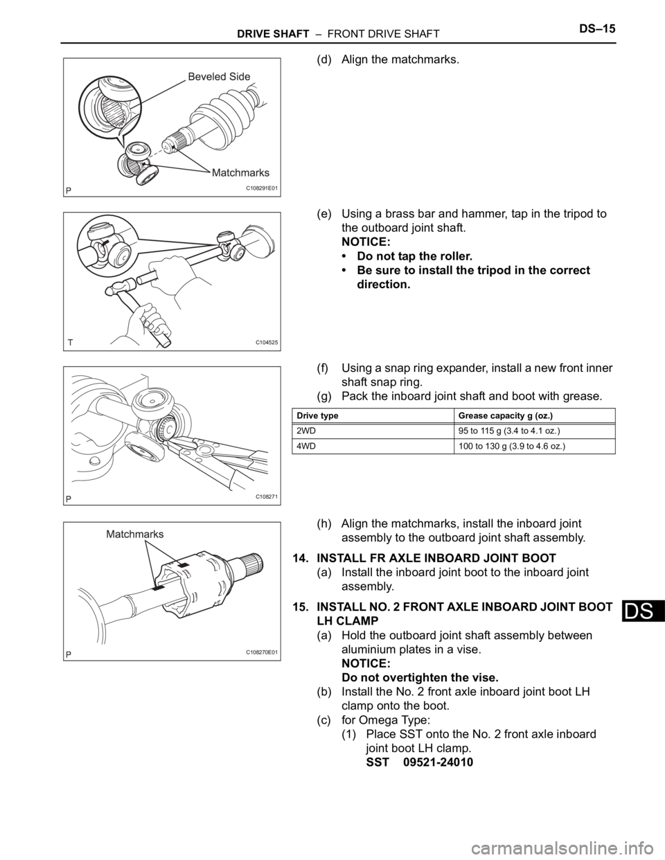
(d) Align the matchmarks.
(e) Using a brass bar and hammer, tap in the tripod to
the outboard joint shaft.
NOTICE:
• Do not tap the roller.
• Be sure to install the tripod in the correct
direction.
(f) Using a snap ring expander, install a new front inner
shaft snap ring.
(g) Pack the inboard joint shaft and boot with grease.
(h) Align the matchmarks, install the inboard joint
assembly to the outboard joint shaft assembly.
14. INSTALL FR AXLE INBOARD JOINT BOOT
(a) Install the inboard joint boot to the inboard joint
assembly.
15. INSTALL NO. 2 FRONT AXLE INBOARD JOINT BOOT
LH CLAMP
(a) Hold the outboard joint shaft assembly between
aluminium plates in a vise.
NOTICE:
Do not overtighten the vise.
(b) Install the No. 2 front axle inboard joint boot LH
clamp onto the boot.
(c) for Omega Type:
(1) Place SST onto the No. 2 front axle inboard
joint boot LH clamp.
SST 09521-24010
C108291E01
C104525
C108271
Drive type Grease capacity g (oz.)
2WD 95 to 115 g (3.4 to 4.1 oz.)
4WD 100 to 130 g (3.9 to 4.6 oz.)
C108270E01
Page 121 of 3000
DS–16DRIVE SHAFT – FRONT DRIVE SHAFT
DS
(2) Tighten the SST so that the No. 2 front axle
inboard joint boot LH clamp is pinched.
SST 09521-24010
NOTICE:
Do not overtighten the SST.
(3) Using SST, measure the clearance of the No. 2
front axle inboard joint boot LH clamp.
SST 09240-00020
Clearance:
0.8 mm (0.031 in.) or less
NOTICE:
When the measured value is greater than
the specified value, retighten the clamp.
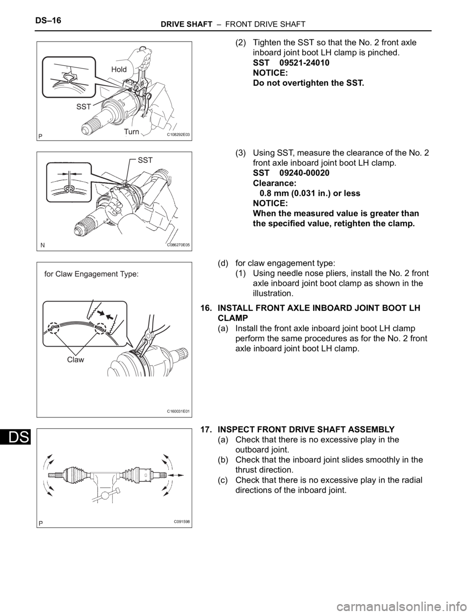
(d) for claw engagement type:
(1) Using needle nose pliers, install the No. 2 front
axle inboard joint boot clamp as shown in the
illustration.
16. INSTALL FRONT AXLE INBOARD JOINT BOOT LH
CLAMP
(a) Install the front axle inboard joint boot LH clamp
perform the same procedures as for the No. 2 front
axle inboard joint boot LH clamp.
17. INSPECT FRONT DRIVE SHAFT ASSEMBLY
(a) Check that there is no excessive play in the
outboard joint.
(b) Check that the inboard joint slides smoothly in the
thrust direction.
(c) Check that there is no excessive play in the radial
directions of the inboard joint.
C108292E03
C086270E05
C160031E01
C091598
Page 161 of 3000

DIFFERENTIAL – REAR DIFFERENTIAL CARRIER OIL SEALDF–7
DF
INSTALLATION
1. INSTALL REAR DIFFERENTIAL DRIVE PINION
BEARING SPACER
(a) Install a new bearing spacer.
2. INSTALL REAR DRIVE PINION FRONT TAPERED
ROLLER BEARING
(a) Install the tapered roller bearing.
3. INSTALL REAR DIFFERENTIAL DRIVE PINION OIL
SLINGER
(a) Install the oil slinger, as shown in the illustration.
4. INSTALL REAR DIFFERENTIAL CARRIER OIL SEAL
(a) Using SST and a hammer, install a new oil seal.
SST 09554-22010
Oil seal drive in depth:
2.0 +- 0.3 mm (0.079 +- 0.012 in.)
(b) Coat MP grease to the oil seal lip.
5. INSTALL REAR DRIVE PINION COMPANION FLANGE
SUB-ASSEMBLY
(a) Using SST, install the companion flange on the
shaft.
SST 09950-30012 (09951-03010, 09953-03010,
09954-03010, 09955-03030, 09956-03020)
NOTICE:
Apply hypoid gear oil to the SST center bolt tip
and threads before use.
6. INSTALL REAR DRIVE PINION NUT
(a) Coat the threads of a new nut with hypoid gear oil
LSD.
(b) Using SST to hold the flange, torque the nut.
SST 09330-00021
Torque: 108 N*m (1,100 kgf*cm, 80 ft.*lbf)
7. INSPECT DIFFERENTIAL DRIVE PINION PRELOAD
(a) Inspect differential drive pinion preload (See page
DF-31).
(b) Using a chisel and a hammer, stake the drive pinion
nut.
C083862
G025655E03
D030957E02
D030847E01
Page 162 of 3000
DF–8DIFFERENTIAL – REAR DIFFERENTIAL CARRIER OIL SEAL
DF
8. INSTALL REAR DIFFERENTIAL DRAIN PLUG
(a) Using a hexagon wrench (10 mm), install the filler
plug with a new gasket.
Torque: 49 N*m (500 kgf*cm, 36 ft.*lbf)
9. ADD DIFFERENTIAL OIL
(a) Fill the rear differential carrier assembly with hypoid
gear oil.
10. INSPECT DIFFERENTIAL OIL
HINT:
(See page DF-3)
11. INSTALL REAR DIFFERENTIAL FILLER PLUG
(a) Using a hexagon wrench (10 mm), install the filler
plug with a new gasket.
Torque: 49 N*m (500 kgf*cm, 36 ft.*lbf)
12. INSTALL PROPELLER WITH CENTER BEARING
SHAFT ASSEMBLY
(a) Install propeller with center bearing shaft assembly
(See page PR-9).
(b) Fully tighten propeller with center bearing shaft
assembly (See page PR-10).
13. INSTALL EXHAUST PIPE ASSEMBLY
HINT:
(See page EX-10)
14. INSPECT FOR EXHAUST GAS LEAK
HINT:
(See page EX-12)
Page 165 of 3000
AH–8AXLE – FRONT AXLE HUB
AH
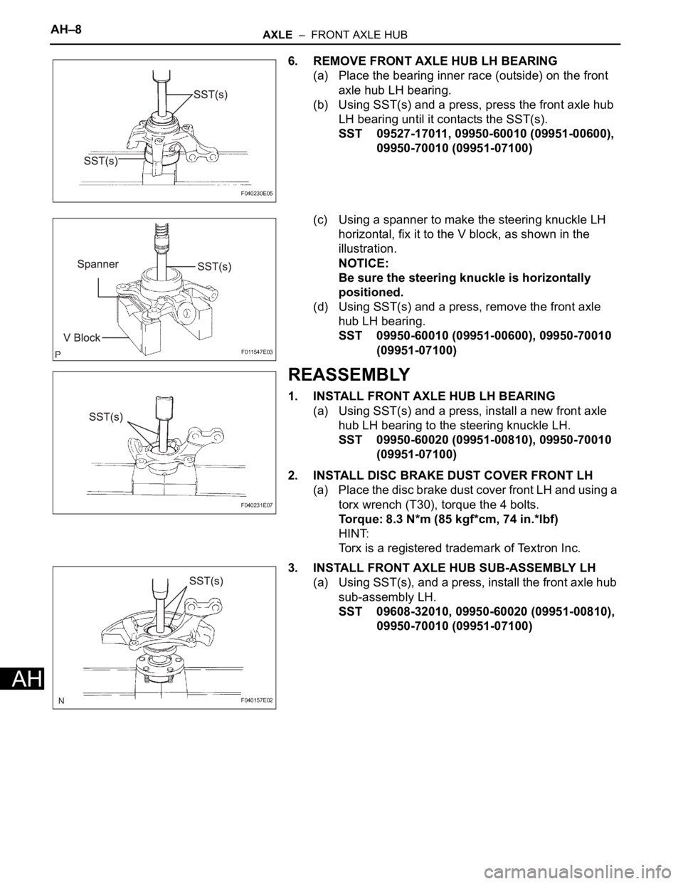
6. REMOVE FRONT AXLE HUB LH BEARING
(a) Place the bearing inner race (outside) on the front
axle hub LH bearing.
(b) Using SST(s) and a press, press the front axle hub
LH bearing until it contacts the SST(s).
SST 09527-17011, 09950-60010 (09951-00600),
09950-70010 (09951-07100)
(c) Using a spanner to make the steering knuckle LH
horizontal, fix it to the V block, as shown in the
illustration.
NOTICE:
Be sure the steering knuckle is horizontally
positioned.
(d) Using SST(s) and a press, remove the front axle
hub LH bearing.
SST 09950-60010 (09951-00600), 09950-70010
(09951-07100)
REASSEMBLY
1. INSTALL FRONT AXLE HUB LH BEARING
(a) Using SST(s) and a press, install a new front axle
hub LH bearing to the steering knuckle LH.
SST 09950-60020 (09951-00810), 09950-70010
(09951-07100)
2. INSTALL DISC BRAKE DUST COVER FRONT LH
(a) Place the disc brake dust cover front LH and using a
torx wrench (T30), torque the 4 bolts.
Torque: 8.3 N*m (85 kgf*cm, 74 in.*lbf)
HINT:
Torx is a registered trademark of Textron Inc.
3. INSTALL FRONT AXLE HUB SUB-ASSEMBLY LH
(a) Using SST(s), and a press, install the front axle hub
sub-assembly LH.
SST 09608-32010, 09950-60020 (09951-00810),
09950-70010 (09951-07100)
F040230E05
F011547E03
F040231E07
F040157E02
Page 166 of 3000
AXLE – FRONT AXLE HUBAH–9
AH
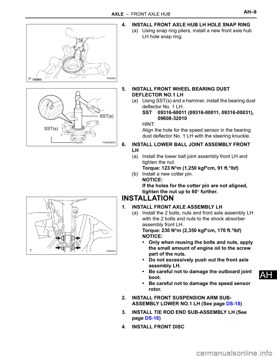
4. INSTALL FRONT AXLE HUB LH HOLE SNAP RING
(a) Using snap ring pliers, install a new front axle hub
LH hole snap ring.
5. INSTALL FRONT WHEEL BEARING DUST
DEFLECTOR NO.1 LH
(a) Using SST(s) and a hammer, install the bearing dust
deflector No. 1 LH.
SST 09316-60011 (09316-00011, 09316-00031),
09608-32010
HINT:
Align the hole for the speed sensor in the bearing
dust deflector No. 1 LH with the steering knuckle.
6. INSTALL LOWER BALL JOINT ASSEMBLY FRONT
LH
(a) Install the lower ball joint assembly front LH and
tighten the nut.
Torque: 123 N*m (1,250 kgf*cm, 91 ft.*lbf)
(b) Install a new cotter pin.
NOTICE:
If the holes for the cotter pin are not aligned,
tighten the nut up to 60
further.
INSTALLATION
1. INSTALL FRONT AXLE ASSEMBLY LH
(a) Install the 2 bolts, nuts and front axle assembly LH
with the 2 bolts and nuts to the shock absorber
assembly front LH.
Torque: 230 N*m (2,350 kgf*cm, 170 ft.*lbf)
NOTICE:
• Only when reusing the bolts and nuts, apply
the small amount of engine oil to the screw
part of the nuts.
• Do not excessively push out the front axle
assembly LH.
• Be careful not to damage the outboard joint
boot.
• Be careful not to damage the speed sensor
rotor.
2. INSTALL FRONT SUSPENSION ARM SUB-
ASSEMBLY LOWER NO.1 LH (See page DS-18)
3. INSTALL TIE ROD END SUB-ASSEMBLY LH (See
page DS-18)
4. INSTALL FRONT DISC
F045465
F045054E03
C083023