Page 81 of 3000

2GR-FE IGNITION – IGNITION COIL AND SPARK PLUGIG–7
IG
(3) Check the spark plug (See page EM-1).
Result
(4) Check the power supply to the ignition coil.
1. Turn the ignition switch to the ON position.
2. Check that there is battery voltage at the
ignition coil positive (+) terminal.
Result
(5) Measure the resistance of the crankshaft
position sensor (See page ES-514).
Result
(6) Check the IGT signal from the ECM (See page
ES-233)
Result
(e) Using a 16 mm (0.63 in.) plug wrench, install the
spark plugs.
Torque: 18 N*m (184 kgf*cm, 13 ft.*lbf)
(f) Connect the 6 fuel injector connectors.
(g) Install the ignition coil assembly (See page IG-10).
2. INSPECT SPARK PLUG
NOTICE:
• Never use a wire brush for cleaning.
• Never attempt to adjust the electrode gap on a
used spark plug.
(a) Check the electrode.
(1) Using a megohmmeter, measure the insulation
resistance.
Standard insulation resistance:
10 M
or higher
HINT:
• If the result is 10 M
or less, clean the plug
and measure the resistance again.
• If a megohmmeter is not available, perform
the following simple inspection instead.
(b) Alternative inspection method:
(1) Quickly accelerate the engine to 4000 rpm 5
times.
Result Proceed to
NG Replace spark plug
OK Go to next step
Result Proceed to
NGCheck wiring between ignition
switch and ignition coil
OK Go to next step
Result Proceed to
NG Replace crankshaft position sensor
OK Go to next step
Result Proceed to
NG Check ECM
OKRepair wiring between ignition coil
and ECM
I039522E10
Page 82 of 3000

IG–82GR-FE IGNITION – IGNITION COIL AND SPARK PLUG
IG
(2) Remove the spark plugs.
(3) Visually check the spark plug.
If the electrode is dry, the spark plug is
functioning properly. If the electrode is damp,
proceed to the next step.
(c) Check the spark plug for any damage to its threads
and insulator. If there is damage, replace the spark
plug.
Recommended spark plug
NOTICE:
Use only the listed spark plug or equivalent to
ensure engine performance and smooth
driveability.
(d) Check the spark plug electrode gap.
Maximum electrode gap for used spark plug:
1.4 mm (0.055 in.)
If the gap is greater than the maximum, replace the
spark plug.
Electrode gap for new spark plug:
1.0 to 1.1 mm (0.039 to 0.043 in.)
(e) Clean the spark plugs.
If the electrode has traces of wet carbon, clean the
electrode with a spark plug cleaner and then dry it.
Standard air pressure:
588 kPa (6 kgf*cm
2, 85 psi)
Standard duration:
20 seconds or less
HINT:
Only use the spark plug cleaner when the electrode
is free of oil. If the electrode has traces of oil, use
gasoline to clean off the oil before using the spark
plug cleaner.
(f) Install the ignition coil assembly and spark plug.
(See page IG-10).
Manufacturer Spark Plug Type
DENSO FK20HR11
A163282E01
B062019
Page 93 of 3000

AX–166U151E AUTOMATIC TRANSAXLE – AUTOMATIC TRANSAXLE ASSEMBLY
AX
INSTALLATION
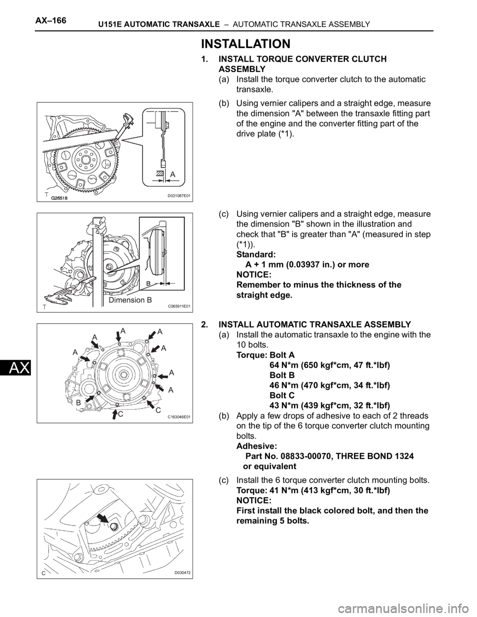
1. INSTALL TORQUE CONVERTER CLUTCH
ASSEMBLY
(a) Install the torque converter clutch to the automatic
transaxle.
(b) Using vernier calipers and a straight edge, measure
the dimension "A" between the transaxle fitting part
of the engine and the converter fitting part of the
drive plate (*1).
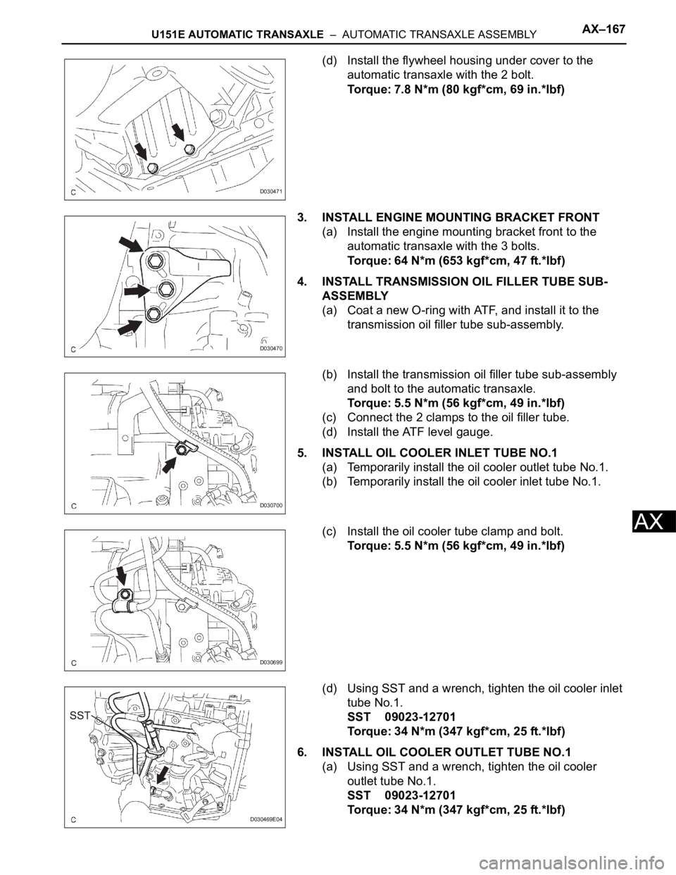
(c) Using vernier calipers and a straight edge, measure
the dimension "B" shown in the illustration and
check that "B" is greater than "A" (measured in step
(*1)).
Standard:
A + 1 mm (0.03937 in.) or more
NOTICE:
Remember to minus the thickness of the
straight edge.
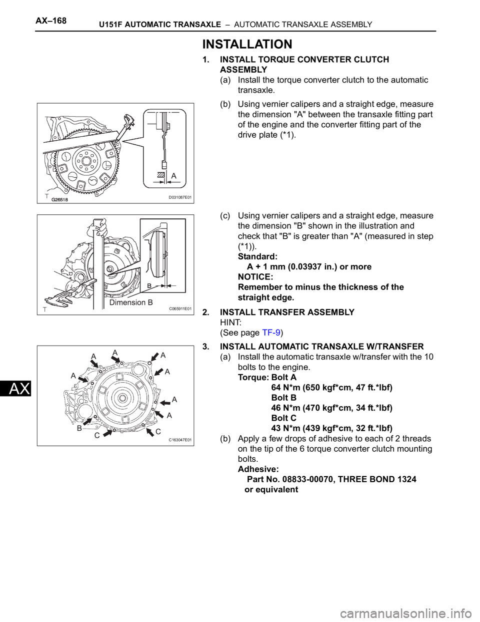
2. INSTALL AUTOMATIC TRANSAXLE ASSEMBLY
(a) Install the automatic transaxle to the engine with the
10 bolts.
Torque: Bolt A
64 N*m (650 kgf*cm, 47 ft.*lbf)
Bolt B
46 N*m (470 kgf*cm, 34 ft.*lbf)
Bolt C
43 N*m (439 kgf*cm, 32 ft.*lbf)
(b) Apply a few drops of adhesive to each of 2 threads
on the tip of the 6 torque converter clutch mounting
bolts.
Adhesive:
Part No. 08833-00070, THREE BOND 1324
or equivalent
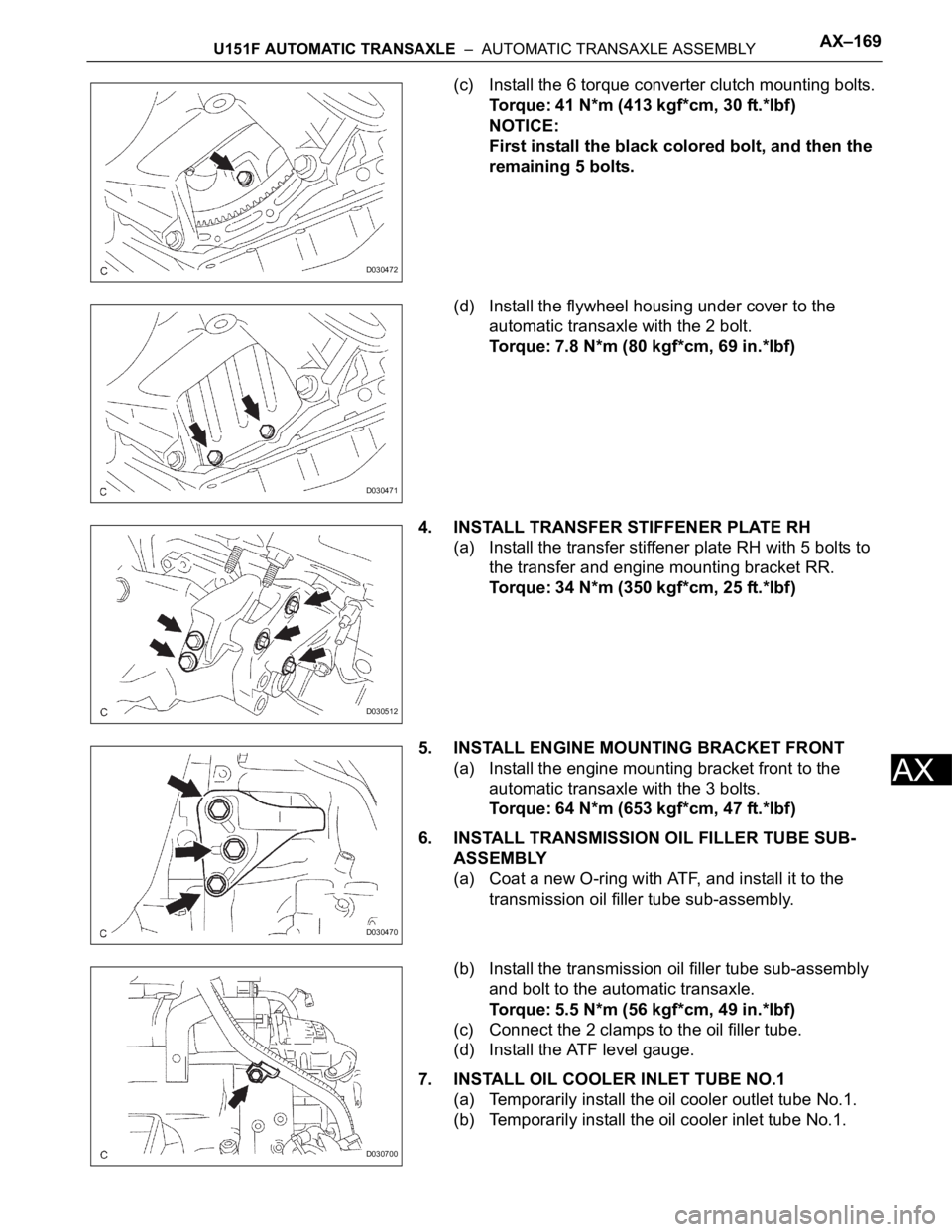
(c) Install the 6 torque converter clutch mounting bolts.
Torque: 41 N*m (413 kgf*cm, 30 ft.*lbf)
NOTICE:
First install the black colored bolt, and then the
remaining 5 bolts.
D031087E01
C065911E01
C163046E01
D030472
Page 94 of 3000

U151E AUTOMATIC TRANSAXLE – AUTOMATIC TRANSAXLE ASSEMBLYAX–167
AX
(d) Install the flywheel housing under cover to the
automatic transaxle with the 2 bolt.
Torque: 7.8 N*m (80 kgf*cm, 69 in.*lbf)
3. INSTALL ENGINE MOUNTING BRACKET FRONT
(a) Install the engine mounting bracket front to the
automatic transaxle with the 3 bolts.
Torque: 64 N*m (653 kgf*cm, 47 ft.*lbf)
4. INSTALL TRANSMISSION OIL FILLER TUBE SUB-
ASSEMBLY
(a) Coat a new O-ring with ATF, and install it to the
transmission oil filler tube sub-assembly.
(b) Install the transmission oil filler tube sub-assembly
and bolt to the automatic transaxle.
Torque: 5.5 N*m (56 kgf*cm, 49 in.*lbf)
(c) Connect the 2 clamps to the oil filler tube.
(d) Install the ATF level gauge.
5. INSTALL OIL COOLER INLET TUBE NO.1
(a) Temporarily install the oil cooler outlet tube No.1.
(b) Temporarily install the oil cooler inlet tube No.1.
(c) Install the oil cooler tube clamp and bolt.
Torque: 5.5 N*m (56 kgf*cm, 49 in.*lbf)
(d) Using SST and a wrench, tighten the oil cooler inlet
tube No.1.
SST 09023-12701
Torque: 34 N*m (347 kgf*cm, 25 ft.*lbf)
6. INSTALL OIL COOLER OUTLET TUBE NO.1
(a) Using SST and a wrench, tighten the oil cooler
outlet tube No.1.
SST 09023-12701
Torque: 34 N*m (347 kgf*cm, 25 ft.*lbf)
D030471
D030470
D030700
D030699
D030469E04
Page 95 of 3000
AX–168U151E AUTOMATIC TRANSAXLE – AUTOMATIC TRANSAXLE ASSEMBLY
AX
7. INSTALL TRANSMISSION CONTROL CABLE
BRACKET NO.1
(a) Install the control cable bracket No.1 with the 2
bolts.
Torque: 12 N*m (122 kgf*cm, 9 ft.*lbf)
8. CONNECT CONNECTORS
(a) Connect the transmission wire connector.
(b) Connect the park/neutral position switch connector.
(c) Connect the 2 speed sensor connectors.
9. INSTALL STARTER ASSEMBLY
(a) Install the starter assembly with the 2 bolts (1).
Torque: 37 N*m (377 kgf*cm, 27 ft.*lbf)
(b) Connect the connector (2).
(c) Connect the starter wire with the nut (3).
Torque: 9.8 N*m (100 kgf*cm, 87 in.*lbf)
10. CONNECT WIRE HARNESS
(a) Connect the wire harness with the bolt.
Torque: 13 N*m (133 kgf*cm, 10 ft.*lbf)
D030467
D030864E03
D030464E03
G025456
Page 96 of 3000
U151E AUTOMATIC TRANSAXLE – AUTOMATIC TRANSAXLE ASSEMBLYAX–169
AX
11. INSTALL WIRE HARNESS CLAMP
(a) Install the 2 clamps and 3 bolts.
Torque: 8.4 N*m (86 kgf*cm, 74 in.*lbf)
(b) Connect the wire harnesses to the clamps.
12. INSTALL TRANSMISSION CONTROL CABLE CLAMP
(a) Install the transmission control cable clamp with the
bolt.
Torque: 12 N*m (122 kgf*cm, 9 ft.*lbf)
13. INSTALL FRONT DRIVE SHAFT ASSEMBLY LH
HINT:
(See page DS-17)
14. INSTALL FRONT DRIVE SHAFT ASSEMBLY RH
HINT:
(See page DS-17)
15. INSTALL ENGINE ASSEMBLY WITH TRANSAXLE
HINT:
(See page EM-44)
16. RESET MEMORY
HINT:
(See page AX-16)
D030465
C083203
Page 103 of 3000

AX–168U151F AUTOMATIC TRANSAXLE – AUTOMATIC TRANSAXLE ASSEMBLY
AX
INSTALLATION
1. INSTALL TORQUE CONVERTER CLUTCH
ASSEMBLY
(a) Install the torque converter clutch to the automatic
transaxle.
(b) Using vernier calipers and a straight edge, measure
the dimension "A" between the transaxle fitting part
of the engine and the converter fitting part of the
drive plate (*1).
(c) Using vernier calipers and a straight edge, measure
the dimension "B" shown in the illustration and
check that "B" is greater than "A" (measured in step
(*1)).
Standard:
A + 1 mm (0.03937 in.) or more
NOTICE:
Remember to minus the thickness of the
straight edge.
2. INSTALL TRANSFER ASSEMBLY
HINT:
(See page TF-9)
3. INSTALL AUTOMATIC TRANSAXLE W/TRANSFER
(a) Install the automatic transaxle w/transfer with the 10
bolts to the engine.
To r q u e : B o l t A
64 N*m (650 kgf*cm, 47 ft.*lbf)
Bolt B
46 N*m (470 kgf*cm, 34 ft.*lbf)
Bolt C
43 N*m (439 kgf*cm, 32 ft.*lbf)
(b) Apply a few drops of adhesive to each of 2 threads
on the tip of the 6 torque converter clutch mounting
bolts.
Adhesive:
Part No. 08833-00070, THREE BOND 1324
or equivalent
D031087E01
C065911E01
C163047E01
Page 104 of 3000

U151F AUTOMATIC TRANSAXLE – AUTOMATIC TRANSAXLE ASSEMBLYAX–169
AX
(c) Install the 6 torque converter clutch mounting bolts.
Torque: 41 N*m (413 kgf*cm, 30 ft.*lbf)
NOTICE:
First install the black colored bolt, and then the
remaining 5 bolts.
(d) Install the flywheel housing under cover to the
automatic transaxle with the 2 bolt.
Torque: 7.8 N*m (80 kgf*cm, 69 in.*lbf)
4. INSTALL TRANSFER STIFFENER PLATE RH
(a) Install the transfer stiffener plate RH with 5 bolts to
the transfer and engine mounting bracket RR.
Torque: 34 N*m (350 kgf*cm, 25 ft.*lbf)
5. INSTALL ENGINE MOUNTING BRACKET FRONT
(a) Install the engine mounting bracket front to the
automatic transaxle with the 3 bolts.
Torque: 64 N*m (653 kgf*cm, 47 ft.*lbf)
6. INSTALL TRANSMISSION OIL FILLER TUBE SUB-
ASSEMBLY
(a) Coat a new O-ring with ATF, and install it to the
transmission oil filler tube sub-assembly.
(b) Install the transmission oil filler tube sub-assembly
and bolt to the automatic transaxle.
Torque: 5.5 N*m (56 kgf*cm, 49 in.*lbf)
(c) Connect the 2 clamps to the oil filler tube.
(d) Install the ATF level gauge.
7. INSTALL OIL COOLER INLET TUBE NO.1
(a) Temporarily install the oil cooler outlet tube No.1.
(b) Temporarily install the oil cooler inlet tube No.1.
D030472
D030471
D030512
D030470
D030700