2007 TOYOTA SIENNA lock
[x] Cancel search: lockPage 183 of 3000
BRAKE CONTROL – ANTI-LOCK BRAKE SYSTEMBC–7
BC
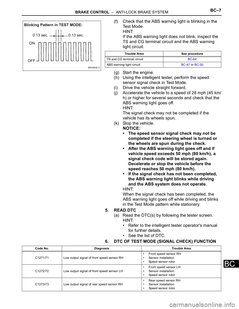
(f) Check that the ABS warning light is blinking in the
Test Mode.
HINT:
If the ABS warning light does not blink, inspect the
TS and CG terminal circuit and the ABS warning
light circuit.
(g) Start the engine.
(h) Using the intelligent tester, perform the speed
sensor signal check in Test Mode.
(i) Drive the vehicle straight forward.
(j) Accelerate the vehicle to a speed of 28 mph (45 km/
h) or higher for several seconds and check that the
ABS warning light goes off.
HINT:
The signal check may not be completed if the
vehicle has its wheels spun.
(k) Stop the vehicle.
NOTICE:
• The speed sensor signal check may not be
completed if the steering wheel is turned or
the wheels are spun during the check.
• After the ABS warning light goes off and if
vehicle speed exceeds 50 mph (80 km/h), a
signal check code will be stored again.
Decelerate or stop the vehicle before the
speed reaches 50 mph (80 km/h).
• If the signal check has not been completed,
the ABS warning light blinks while driving
and the ABS system does not operate.
HINT:
When the signal check has been completed, the
ABS warning light goes off while driving and blinks
in the Test Mode pattern while stationary.
5. READ DTC
(a) Read the DTC(s) by following the tester screen.
HINT:
• Refer to the intelligent tester operator's manual
for further details.
• See the list of DTC.
6. DTC OF TEST MODE (SIGNAL CHECK) FUNCTION
BR03904E13
Trouble Area See procedure
TS and CG terminal circuitBC-64
ABS warning light circuitBC-47 or BC-50
Code No. Diagnosis Trouble Area
C1271/71 Low output signal of front speed sensor RH• Front speed sensor RH
• Sensor installation
• Speed sensor rotor
C1272/72 Low output signal of front speed sensor LH• Front speed sensor LH
• Sensor installation
• Speed sensor rotor
C1273/73 Low output signal of rear speed sensor RH• Rear speed sensor RH
• Sensor installation
• Speed sensor rotor
Page 184 of 3000

BC–8BRAKE CONTROL – ANTI-LOCK BRAKE SYSTEM
BC
HINT:
The codes in this table are output only in Test Mode
(signal check).
C1274/74 Low output signal of rear speed sensor LH• Rear speed sensor LH
• Sensor installation
• Speed sensor rotor
C1275/75Abnormal change in output signal of front speed sensor
RHSpeed sensor rotor
C1276/76Abnormal change in output signal of front speed sensor
LHSpeed sensor rotor
C1277/77Abnormal change in output signal of rear speed sensor
RHSpeed sensor rotor
C1278/78Abnormal change in output signal of rear speed sensor
LHSpeed sensor rotor Code No. Diagnosis Trouble Area
Page 186 of 3000
BR–12BRAKE – BRAKE PEDAL
BR
DISASSEMBLY
1. REMOVE STOP LIGHT SWITCH ASSEMBLY
(a) Turn the stop light switch assembly
counterclockwise and remove the stop light switch
assembly.
(b) Remove the stop light switch mounting adjuster
from the brake pedal support sub-assembly.
2. REMOVE STOP LIGHT SWITCH CUSHION
(a) Remove the stop light switch cushion from the brake
pedal sub-assembly.
3. REMOVE BRAKE PEDAL
(a) Remove the 2 brake pedal shafts, 2 nuts and brake
pedal from the brake pedal support sub-assembly.
4. REMOVE BRAKE PEDAL BUSH
(a) Remove the 4 brake pedal bushes from the brake
pedal.
5. REMOVE BRAKE PEDAL SHAFT COLLAR
(a) Remove the 2 brake pedal shaft collars from the
brake pedal.
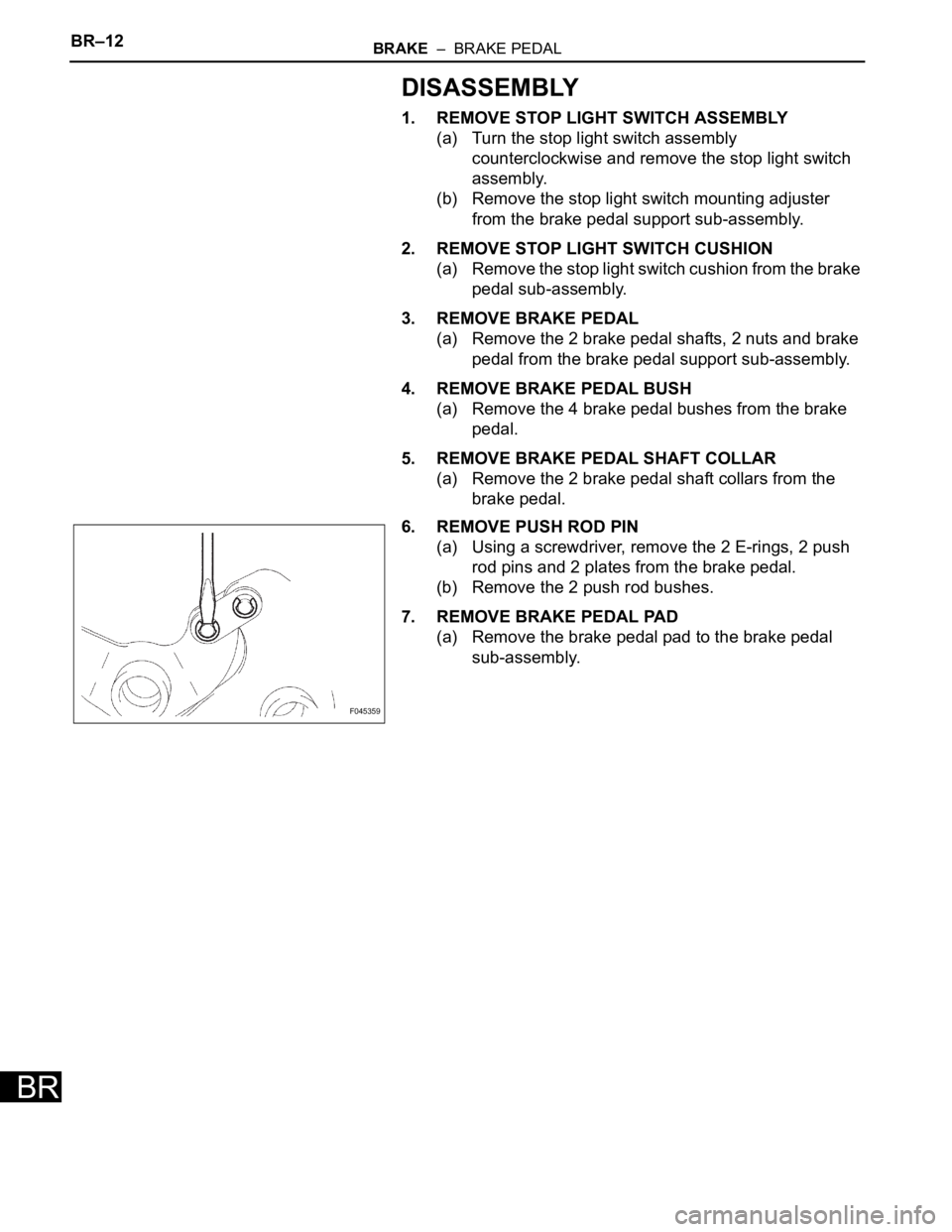
6. REMOVE PUSH ROD PIN
(a) Using a screwdriver, remove the 2 E-rings, 2 push
rod pins and 2 plates from the brake pedal.
(b) Remove the 2 push rod bushes.
7. REMOVE BRAKE PEDAL PAD
(a) Remove the brake pedal pad to the brake pedal
sub-assembly.
F045359
Page 187 of 3000
PARKING BRAKE – PARKING BRAKE PEDALPB–5
PB
REMOVAL
1. DISCONNECT BATTERY NEGATIVE TERMINAL
2. REMOVE FRONT DOOR SCUFF PLATE LH
3. REMOVE COWL SIDE TRIM BOARD LH
4. REMOVE INSTRUMENT PANEL FINISH PANEL SUB-
ASSEMBLY LOWER LH (See page IP-6)
5. REMOVE REAR DOOR SCUFF PLATE RH
6. REMOVE REAR DOOR SCUFF PLATE LH
7. REMOVE FRONT SEAT ASSEMBLY LH
HINT:
• Manual Seat Type (See page SE-48)
• Power Seat Type (See page SE-58)
• Fold Flat Type (See page SE-40)
8. REMOVE REAR SEAT NO.1 ASSEMBLY
HINT:
• Captain Seat Type (See page SE-68)
• Center Seat Type (See page SE-77)
9. REMOVE REAR FLOOR SEAT LOCK COVER
10. REMOVE REAR FLOOR SEAT LOCK COVER
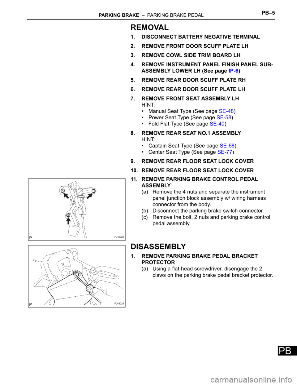
11. REMOVE PARKING BRAKE CONTROL PEDAL
ASSEMBLY
(a) Remove the 4 nuts and separate the instrument
panel junction block assembly w/ wiring harness
connector from the body.
(b) Disconnect the parking brake switch connector.
(c) Remove the bolt, 2 nuts and parking brake control
pedal assembly.
DISASSEMBLY
1. REMOVE PARKING BRAKE PEDAL BRACKET
PROTECTOR
(a) Using a flat-head screwdriver, disengage the 2
claws on the parking brake pedal bracket protector.
F045025
F045029
Page 188 of 3000
PB–6PARKING BRAKE – PARKING BRAKE PEDAL
PB
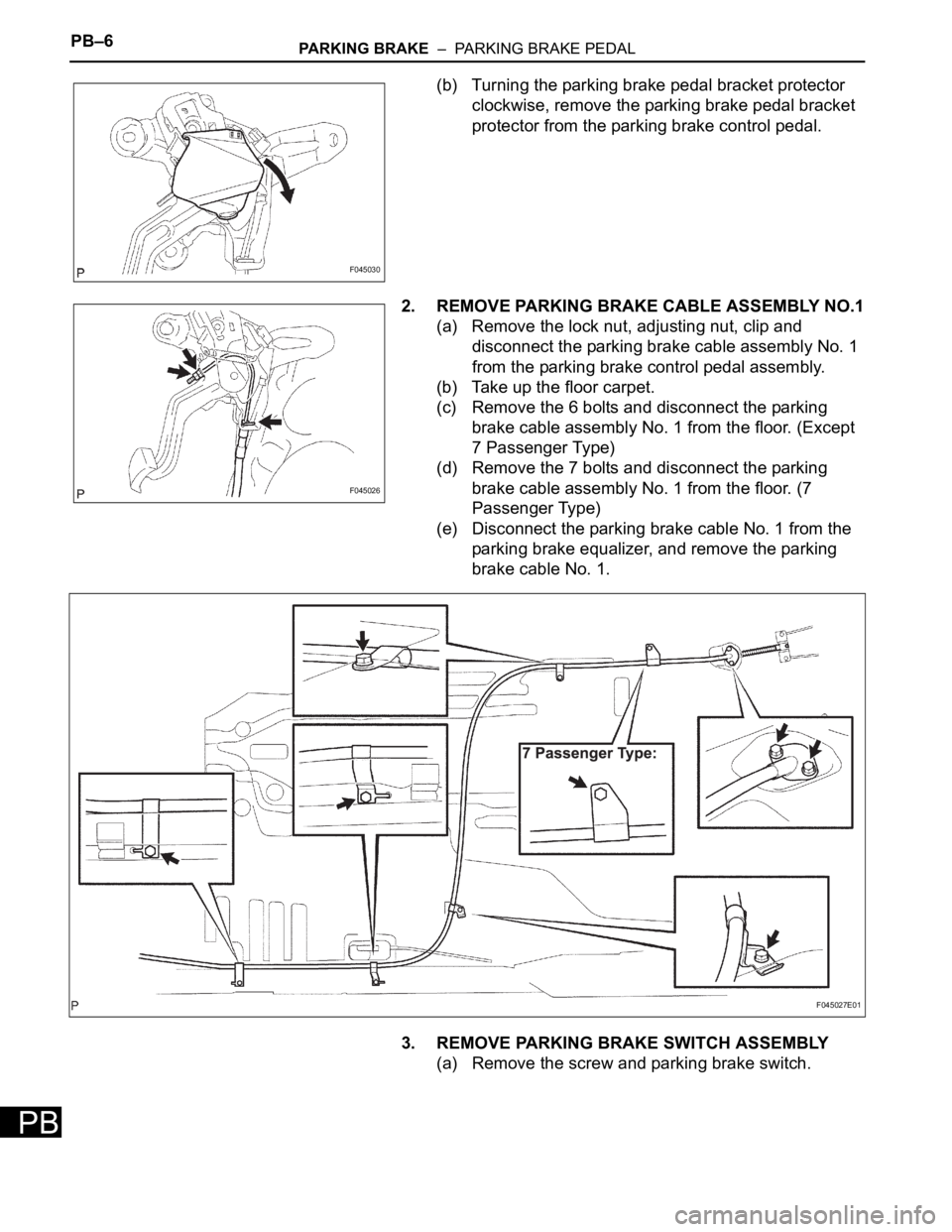
(b) Turning the parking brake pedal bracket protector
clockwise, remove the parking brake pedal bracket
protector from the parking brake control pedal.
2. REMOVE PARKING BRAKE CABLE ASSEMBLY NO.1
(a) Remove the lock nut, adjusting nut, clip and
disconnect the parking brake cable assembly No. 1
from the parking brake control pedal assembly.
(b) Take up the floor carpet.
(c) Remove the 6 bolts and disconnect the parking
brake cable assembly No. 1 from the floor. (Except
7 Passenger Type)
(d) Remove the 7 bolts and disconnect the parking
brake cable assembly No. 1 from the floor. (7
Passenger Type)
(e) Disconnect the parking brake cable No. 1 from the
parking brake equalizer, and remove the parking
brake cable No. 1.
3. REMOVE PARKING BRAKE SWITCH ASSEMBLY
(a) Remove the screw and parking brake switch.
F045030
F045026
F045027E01
Page 190 of 3000
SR–4STEERING COLUMN – STEERING SYSTEM
SR
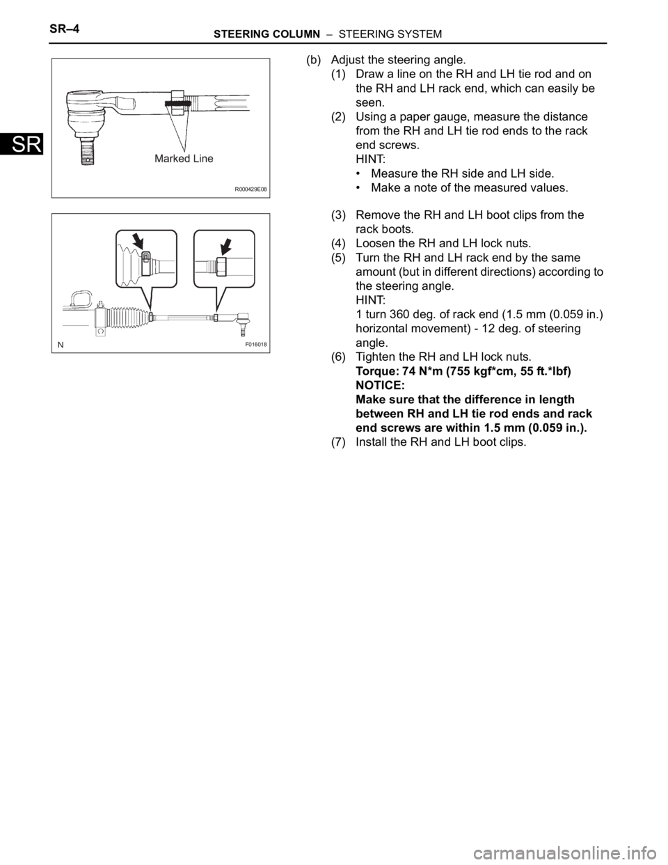
(b) Adjust the steering angle.
(1) Draw a line on the RH and LH tie rod and on
the RH and LH rack end, which can easily be
seen.
(2) Using a paper gauge, measure the distance
from the RH and LH tie rod ends to the rack
end screws.
HINT:
• Measure the RH side and LH side.
• Make a note of the measured values.
(3) Remove the RH and LH boot clips from the
rack boots.
(4) Loosen the RH and LH lock nuts.
(5) Turn the RH and LH rack end by the same
amount (but in different directions) according to
the steering angle.
HINT:
1 turn 360 deg. of rack end (1.5 mm (0.059 in.)
horizontal movement) - 12 deg. of steering
angle.
(6) Tighten the RH and LH lock nuts.
Torque: 74 N*m (755 kgf*cm, 55 ft.*lbf)
NOTICE:
Make sure that the difference in length
between RH and LH tie rod ends and rack
end screws are within 1.5 mm (0.059 in.).
(7) Install the RH and LH boot clips.
R000429E08
F016018
Page 197 of 3000

SS–10SERVICE SPECIFICATIONS – 2GR-FE ENGINE MECHANICAL
SS
TORQUE SPECIFICATIONS
Part Tightened N*m kgf*cm ft.*lbf
Ignition coil assembly x Cylinder head cover sub-assembly 10 102 7
No. 1 engine hanger x Cylinder head sub-assembly RH 33 337 24
No. 2 engine hanger x Cylinder head sub-assembly LH 33 337 24
Engine mounting bracket RH x Cylinder block sub-assembly 54 551 40
No. 1 oil level gauge guide x Cylinder head sub-assembly 21 214 15
No. 2 oil level gauge guide x Cylinder block sub-assembly 21 214 15
No. 2 idler pulley sub-assembly x Timing chain cover sub-assembly 43 438 32
V-ribbed belt tensioner assembly x Cylinder block sub-assembly 43 438 32
Intake manifold x Cylinder head sub-assembly 21 214 15
Exhaust manifold sub-assembly RH x Cylinder head sub-assembly
RH21 214 15
Exhaust manifold sub-assembly LH x Cylinder head sub-assembly LH 21 214 15
Drive plate & ring gear sub-assembly x Crankshaft 83 850 61
Air cleaner case sub-assembly x Body 5.0 51 44 in.*lbf
Air cleaner case sub-assembly x Air cleaner bracket 5.0 51 44 in.*lbf
Engine coolant temperature x water by-pass joint RR 20 200 14
Engine assembly with Transaxle x Body A 85 867 63
B 32 329 24
No. 2 manifold stay x Exhaust manifold sub-assembly LH 34 347 25
No. 2 manifold stay x Cylinder block sub-assembly 34 347 25
No. 1 air cleaner inlet x Body 5.0 51 44 in.*lbf
No. 2 air cleaner inlet x Body 5.0 51 44 in.*lbf
Battery clamp x Body Bolt 5.5 56 49 in.*lbf
Nut 5.5 56 49 in.*lbf
Throttle body bracket x Intake air surge tank assembly 21 214 15
Throttle body bracket x Cylinder head cover sub-assembly RH 21 21415
No. 1 surge tank stay x Intake air surge tank assembly 21 214 15
No. 1 surge tank stay x Cylinder head cover sub-assembly RH 21 21415
No. 1 cowl top to cowl brace inner x Body 7.5 76 66 in.*lbf
No. 1 cowl top to cowl brace inner x Front outer cowl top panel sub-
assembly7.5 76 66 in.*lbf
Front outer cowl top panel sub-assembly x Body 7.5 76 66 in.*lbf
Fuel pump resistor x Front outer cowl top panel sub-assembly 7.576 66 in.*lbf
Radio setting condenser x Cylinder head cover sub-assembly RH 10102 7
Radio setting condense x Cylinder head cover sub-assembly LH 10 102 7
Intake air resonator sub-assembly x Body 5.0 51 44 in.*lbf
Air cleaner bracket x Body 7.8 80 69 in.*lbf
No. 1 vacuum switching valve assembly x Cylinder head cover sub-
assembly10 102 7
Engine mounting bracket RR x Cylinder block sub-assembly 64 650 47
Steering intermediate shaft x Steering gear 35 360 26
Stabilizer link x Shock absorber 74 755 55
Tie rod assembly x Steering gear 49 500 36
Front speed sensor x Front axle 8.0 85 71 in.*lbf
Front axle hub nut x Front drive shaft 294 2998 217
Cooler compressor assembly x V-ribbed belt tensioner 25 250 18
Cooler compressor assembly x Discharge hose sub-assembly 5.4 55 48 in.*lbf
Cooler compressor assembly x Suction hose sub-assembly 5.4 55 48 in.*lbf
Page 198 of 3000

SERVICE SPECIFICATIONS – 2GR-FE ENGINE MECHANICALSS–11
SS
Engine mounting control bracket x No. 1 engine
front mounting bracket LH
Bolt A 44 450 32
Bolt B 38 388 28
Nut 23 235 17
Engine assembly with Transaxle x Front frame
assemblyNut A 87 887 64
Nut B 95 969 70
Engine assembly with Transaxle x engine mounting insulator RR 78795 58
Drive shaft bearing bracket x Cylinder block sub-assembly 64 650 47
No. 2 exhaust manifold heat insulator x Exhaust manifold sub-
assembly LH8.5 87 75 in.*lbf
Engine oil pressure switch assembly x Oil pan sub-assembly 21 21415
No. 2 engine mounting stay RH x Intake manifold 21 214 15
No. 2 timing gear cover x Chain cover sub-assembly 6.0 61 53 in.*lbf
No. 1 engine front mounting bracket LH x Chain cover 54 551 40
Camshaft bearing cap x Camshaft housing 1st 10 102 7
2nd 16 163 12
Camshaft housing x Cylinder head sub-assembly 28 286 21
Chain tensioner No. 1 x Cylinder head sub-assembly 10 102 7
Chain tensioner No. 2 x Cylinder head sub-assembly 21 214 15
Chain tensioner No. 3 x Cylinder head sub-assembly 21 214 15
Camshaft timing gear assembly x Camshaft 100 1,020 74
Camshaft timing exhaust gear assembly x Camshaft 100 1,020 74
Engine rear oil seal retainer x Cylinder block sub-assembly 10 1027
Knock control sensor x Cylinder block sub-assembly 20 204 15
Water inlet pipe x Cylinder block sub-assembly 10 102 7
Cylinder head sub-assembly RH x Cylinder
block sub-assembly1st 36 367 27
2nd Turn 90
Turn 90Turn 90
3nd Turn 90Turn 90Turn 90
Cylinder head sub-assembly LH x Cylinder
block sub-assembly
Recessed head 1st 36 367 27
2nd Turn 90
Turn 90Turn 90
3nd Turn 90Turn 90Turn 90
14 mm (0.55 in.)
head30 306 22
Chain vibration damper No. 1 x Cylinder block sub-assembly 23 23017
No. 2 Idle gear shaft x Cylinder block sub-assembly 60 612 44
Timing chain cover plate x Timing chain cover sub-assembly 9.1 9381 in.*lbf
Timing chain cover sub-assembly x Cylinder
head and block
Areas 1: Bolt 21 214 15
Areas 2: Bolt 21 214 15
Areas 3: Bolt and
Nut21 214 15
Areas 4: Bolt A 43 438 32
Areas 4: Except
Bolt A21 214 15
Water pump assembly x Timing chain cover sub-assembly 9.1 93 81 in.*lbf
Oil pan baffle plate x Cylinder block sub-assembly 10 102 7
Oil pan stud bolt x Cylinder block and timing chain cover sub-
assembly10 102 7
Oil pan stud bolt x No. 2 oil pan sub-assembly 4.0 41 35 in.*lbf
Oil cooler stud bolt x Oil pan sub-assembly 10 102 7Part Tightened N*m kgf*cm ft.*lbf