Page 1305 of 3000
2GR-FE LUBRICATION – OIL PUMPLU–13
LU
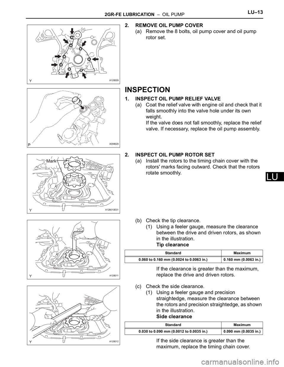
2. REMOVE OIL PUMP COVER
(a) Remove the 8 bolts, oil pump cover and oil pump
rotor set.
INSPECTION
1. INSPECT OIL PUMP RELIEF VALVE
(a) Coat the relief valve with engine oil and check that it
falls smoothly into the valve hole under its own
weight.
If the valve does not fall smoothly, replace the relief
valve. If necessary, replace the oil pump assembly.
2. INSPECT OIL PUMP ROTOR SET
(a) Install the rotors to the timing chain cover with the
rotors' marks facing outward. Check that the rotors
rotate smoothly.
(b) Check the tip clearance.
(1) Using a feeler gauge, measure the clearance
between the drive and driven rotors, as shown
in the illustration.
Tip clearance
If the clearance is greater than the maximum,
replace the drive and driven rotors.
(c) Check the side clearance.
(1) Using a feeler gauge and precision
straightedge, measure the clearance between
the rotors and precision straightedge, as shown
in the illustration.
Side clearance
If the side clearance is greater than the
maximum, replace the timing chain cover.
A128009
A094628
A128010E01
A128011
Standard Maximum
0.060 to 0.160 mm (0.0024 to 0.0063 in.) 0.160 mm (0.0063 in.)
A128012
Standard Maximum
0.030 to 0.090 mm (0.0012 to 0.0035 in.) 0.090 mm (0.0035 in.)
Page 2075 of 3000
DS–22DRIVE SHAFT – REAR DRIVE SHAFT (for 4WD)
DS
REMOVAL
1. REMOVE REAR WHEEL
2. REMOVE TAIL EXHAUST PIPE ASSEMBLY (See page
EX-8)
3. SEPARATE REAR SPEED SENSOR
(a) Remove the bolt and the speed sensor from the
axle carrier.
NOTICE:
• Be careful not to damage the speed sensor.
• Prevent foreign matter from adhering to the
speed sensor.
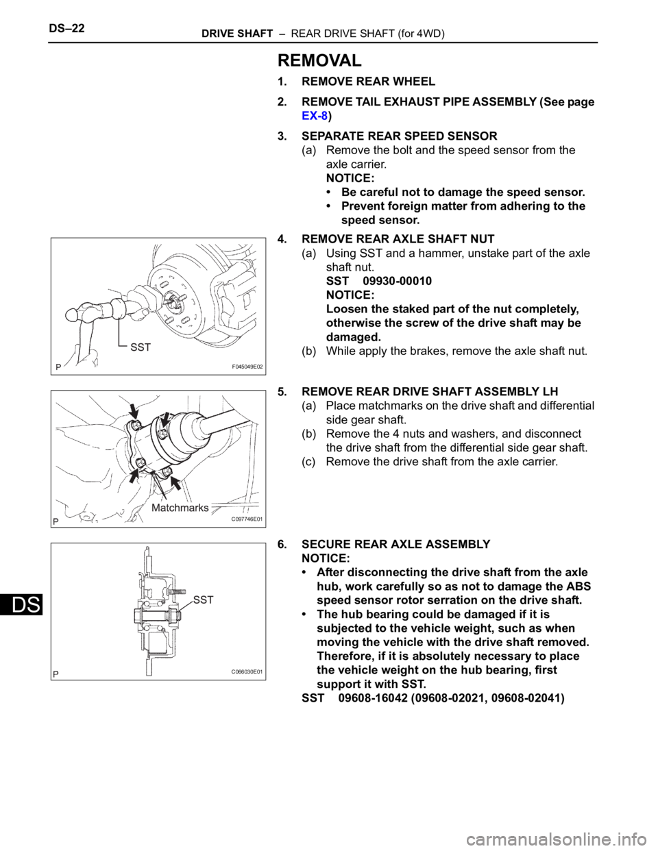
4. REMOVE REAR AXLE SHAFT NUT
(a) Using SST and a hammer, unstake part of the axle
shaft nut.
SST 09930-00010
NOTICE:
Loosen the staked part of the nut completely,
otherwise the screw of the drive shaft may be
damaged.
(b) While apply the brakes, remove the axle shaft nut.
5. REMOVE REAR DRIVE SHAFT ASSEMBLY LH
(a) Place matchmarks on the drive shaft and differential
side gear shaft.
(b) Remove the 4 nuts and washers, and disconnect
the drive shaft from the differential side gear shaft.
(c) Remove the drive shaft from the axle carrier.
6. SECURE REAR AXLE ASSEMBLY
NOTICE:
• After disconnecting the drive shaft from the axle
hub, work carefully so as not to damage the ABS
speed sensor rotor serration on the drive shaft.
• The hub bearing could be damaged if it is
subjected to the vehicle weight, such as when
moving the vehicle with the drive shaft removed.
Therefore, if it is absolutely necessary to place
the vehicle weight on the hub bearing, first
support it with SST.
SST 09608-16042 (09608-02021, 09608-02041)
F045049E02
C097746E01
C066030E01
Page 2082 of 3000
DRIVE SHAFT – FRONT DRIVE SHAFTDS–7
DS
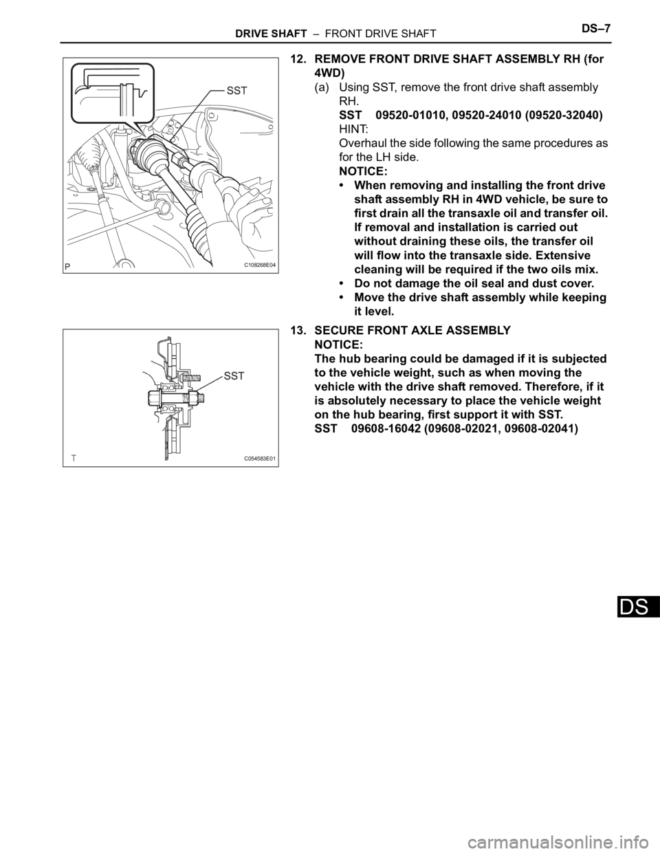
12. REMOVE FRONT DRIVE SHAFT ASSEMBLY RH (for
4WD)
(a) Using SST, remove the front drive shaft assembly
RH.
SST 09520-01010, 09520-24010 (09520-32040)
HINT:
Overhaul the side following the same procedures as
for the LH side.
NOTICE:
• When removing and installing the front drive
shaft assembly RH in 4WD vehicle, be sure to
first drain all the transaxle oil and transfer oil.
If removal and installation is carried out
without draining these oils, the transfer oil
will flow into the transaxle side. Extensive
cleaning will be required if the two oils mix.
• Do not damage the oil seal and dust cover.
• Move the drive shaft assembly while keeping
it level.
13. SECURE FRONT AXLE ASSEMBLY
NOTICE:
The hub bearing could be damaged if it is subjected
to the vehicle weight, such as when moving the
vehicle with the drive shaft removed. Therefore, if it
is absolutely necessary to place the vehicle weight
on the hub bearing, first support it with SST.
SST 09608-16042 (09608-02021, 09608-02041)
C108268E04
C054583E01
Page 2097 of 3000
DS–22DRIVE SHAFT – REAR DRIVE SHAFT (for 4WD)
DS
REMOVAL
1. REMOVE REAR WHEEL
2. REMOVE TAIL EXHAUST PIPE ASSEMBLY (See page
EX-8)
3. SEPARATE REAR SPEED SENSOR
(a) Remove the bolt and the speed sensor from the
axle carrier.
NOTICE:
• Be careful not to damage the speed sensor.
• Prevent foreign matter from adhering to the
speed sensor.
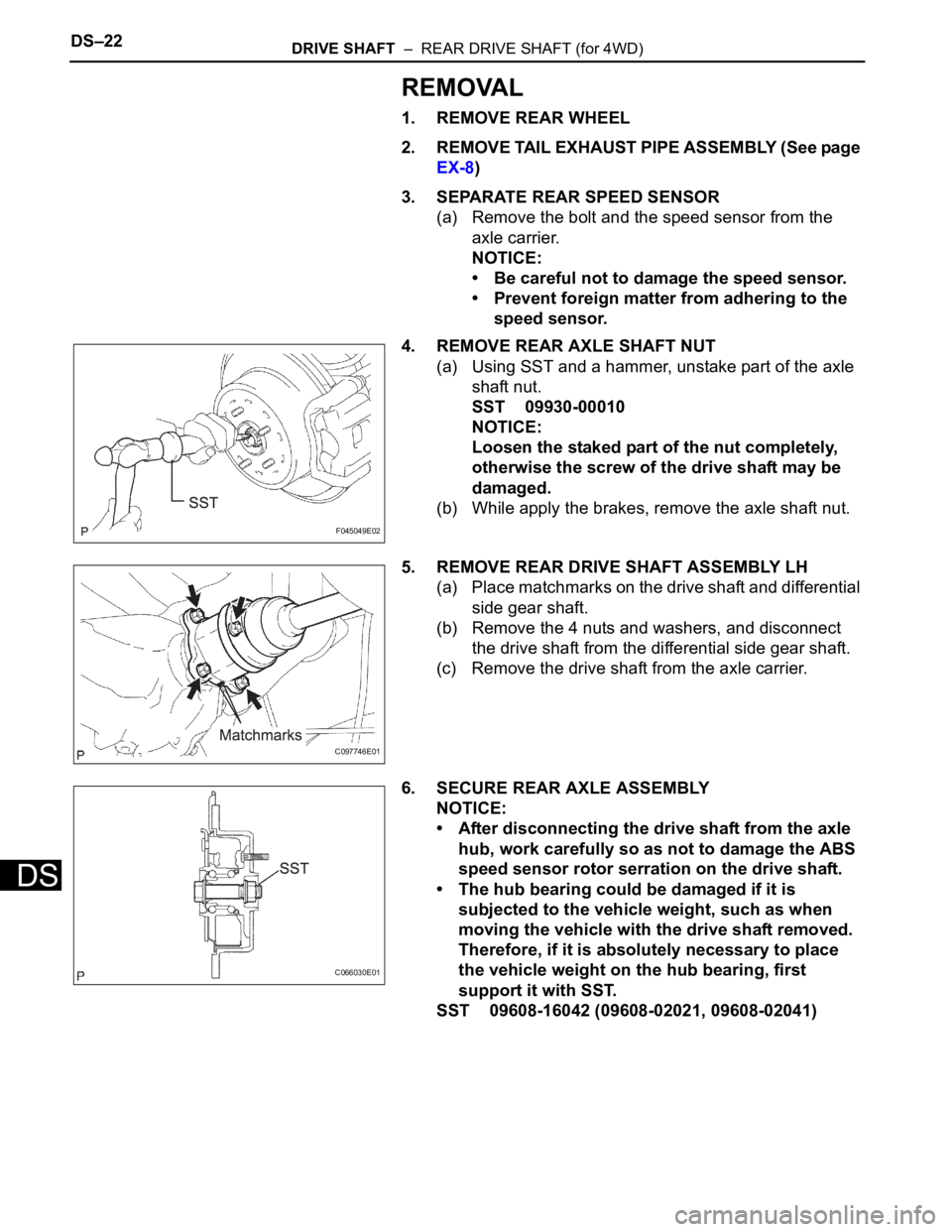
4. REMOVE REAR AXLE SHAFT NUT
(a) Using SST and a hammer, unstake part of the axle
shaft nut.
SST 09930-00010
NOTICE:
Loosen the staked part of the nut completely,
otherwise the screw of the drive shaft may be
damaged.
(b) While apply the brakes, remove the axle shaft nut.
5. REMOVE REAR DRIVE SHAFT ASSEMBLY LH
(a) Place matchmarks on the drive shaft and differential
side gear shaft.
(b) Remove the 4 nuts and washers, and disconnect
the drive shaft from the differential side gear shaft.
(c) Remove the drive shaft from the axle carrier.
6. SECURE REAR AXLE ASSEMBLY
NOTICE:
• After disconnecting the drive shaft from the axle
hub, work carefully so as not to damage the ABS
speed sensor rotor serration on the drive shaft.
• The hub bearing could be damaged if it is
subjected to the vehicle weight, such as when
moving the vehicle with the drive shaft removed.
Therefore, if it is absolutely necessary to place
the vehicle weight on the hub bearing, first
support it with SST.
SST 09608-16042 (09608-02021, 09608-02041)
F045049E02
C097746E01
C066030E01
Page 2255 of 3000
TW–4TIRE AND WHEEL – TIRE AND WHEEL SYSTEM
TW
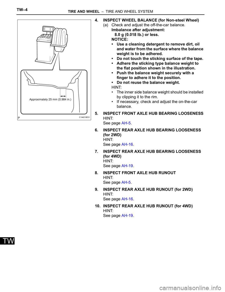
4. INSPECT WHEEL BALANCE (for Non-steel Wheel)
(a) Check and adjust the off-the-car balance.
Imbalance after adjustment:
8.0 g (0.018 lb.) or less.
NOTICE:
• Use a cleaning detergent to remove dirt, oil
and water from the surface where the balance
weight is to be adhered.
• Do not touch the sticking surface of the tape.
• Adhere the sticking type balance weight to
the flat position shown in the illustration.
• Push the balance weight securely with a
finger to adhere it to the position.
• Do not reuse the balance weight.
HINT:
• The inner side balance weight should be installed
by clipping it to the rim.
• If necessary, check and adjust the on-the-car
balance.
5. INSPECT FRONT AXLE HUB BEARING LOOSENESS
HINT:
See page AH-5.
6. INSPECT REAR AXLE HUB BEARING LOOSENESS
(for 2WD)
HINT:
See page AH-16.
7. INSPECT REAR AXLE HUB BEARING LOOSENESS
(for 4WD)
HINT:
See page AH-19.
8. INSPECT FRONT AXLE HUB RUNOUT
HINT:
See page AH-5.
9. INSPECT REAR AXLE HUB RUNOUT (for 2WD)
HINT:
See page AH-16.
10. INSPECT REAR AXLE HUB RUNOUT (for 4WD)
HINT:
See page AH-19.
C144018E01
Page 2270 of 3000
TW–12TIRE AND WHEEL – TIRE PRESSURE WARNING SYSTEM
TW
2. IN CASE OF TIRE AND WHEEL REPLACEMENT
(a) When tires and wheels are replaced, always ensure
that each transmitter ID is correctly registered.
3. IN CASE OF REPLACEMENT OF TIRE PRESSURE
WARNING ECU, TIRE PRESSURE WARNING VALVE
AND TRANSMITTER, OR TIRE(S) WITH DIFFERENT
TIRE PRESSURE
(a) Initialize the tire pressure warning system after any
of the following is performed:
• Replacing the tire pressure warning ECU or the
tire pressure warning valve and transmitter.
• Installing tire(s) which require different tire
pressure.
• Changing the tire inflation pressure by changing
traveling speed or load weight, etc.
HINT:
The tire pressure warning system will not operate
properly if it is not initialized (See page TW-23).
4. FAIL-SAFE FUNCTION
(a) When a system malfunction occurs in the tire
pressure warning system, the tire pressure warning
light comes on after blinking for 1 minute and
informs the driver of the system failure.
(b) The result of this diagnosis is stored in the tire
pressure warning ECU.
5. CHECK TIRE PRESSURE AFTER REPAIRS
(a) After repairs, confirm that the actual tire pressures
are displayed in DATA LIST (See page TW-35).
Page 2725 of 3000
PS–14POWER STEERING – VANE PUMP
PS
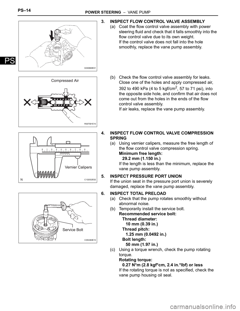
3. INSPECT FLOW CONTROL VALVE ASSEMBLY
(a) Coat the flow control valve assembly with power
steering fluid and check that it falls smoothly into the
flow control valve due to its own weight.
If the control valve does not fall into the hole
smoothly, replace the vane pump assembly.
(b) Check the flow control valve assembly for leaks.
Close one of the holes and apply compressed air,
392 to 490 kPa (4 to 5 kgf/cm
2, 57 to 71 psi), into
the opposite side hole, and confirm that air does not
come out from the holes in the ends of the flow
control valve assembly.
If air leaks, replace the vane pump assembly.
4. INSPECT FLOW CONTROL VALVE COMPRESSION
SPRING
(a) Using vernier calipers, measure the free length of
the flow control valve compression spring.
Minimum free length:
29.2 mm (1.150 in.)
If the length is less than the minimum, replace the
vane pump assembly.
5. INSPECT PRESSURE PORT UNION
If the union seat in the pressure port union is severely
damaged, replace the vane pump assembly.
6. INSPECT TOTAL PRELOAD
(a) Check that the pump rotates smoothly without
abnormal noise.
(b) Temporarily install the service bolt.
Recommended service bolt:
Thread diameter:
10 mm (0.39 in.)
Thread pitch:
1.25 mm (0.0492 in.)
Bolt length:
50 mm (1.97 in.)
(c) Using a torque wrench, check the pump rotating
torque.
Rotating torque:
0.27 N*m (2.8 kgf*cm, 2.4 in.*lbf) or less
If the rotating torque is not as specified, check the
vane pump housing oil seal.
G030668E01
R007591E10
C132032E02
C053369E10