Page 832 of 3000

ES–482GR-FE ENGINE CONTROL SYSTEM – SFI SYSTEM
ES
O2FT B2 S2 Fuel trim at heated oxygen sensor Same as SHORT FT #2
AF FT B1 S1 Fuel trim at A/F sensor -
AF FT B2 S1 Fuel trim at A/F sensor -
CAT TEMP B1 S1 Catalyst temperature -
CAT TEMP B2 S1 Catalyst temperature -
CAT TEMP B1 S2 Catalyst temperature -
CAT TEMP B2 S2 Catalyst temperature -
S O2S B1 S2 Heated oxygen sensor impedance (Sensor 2) -
S O2S B2 S2 Heated oxygen sensor impedance (Sensor 2) -
INI COOL TEMP Initial engine coolant temperature -
INI INTAKE TEMP Initial intake air temperature -
INJ VOL Injection volume -
STARTER SIG Starter signal -
PS SW Power steering signal -
PS SIGNAL Power steering signal (history)This signal status usually ON until ignition
switch turned off
CTP SW Closed throttle position switch -
A/C SIGNAL A/C signal -
ELECT LOAD SIG Electrical load signal -
STOP LIGHT SW Stop light switch -
BATTERY VOLTAGE Battery voltage -
ATM PRESSURE Atmospheric pressure -
FUEL PMP SP CTL Fuel pump speed control status -
ACIS VSVVSV for Air Intake Control Induction System
(AICS)-
VVT CTRL B2 VVT control (bank 2 Intake side) status -
EVAP (Purge) VSV EVAP purge VSV -
FUEL PUMP/SPD Fuel pump speed statusVSV for EVAP controlled by ECM (ground
side duty control)
VACUUM PUMP Key-off EVAP system pump status -
EVAP VENT VAL Key-off EVAP system vent valve status -
FAN MOTOR Electric fan motor -
TC/TE1 TC and TE1 terminals of DLC3 -
ACM ACM control status -
VVTL AIM ANGL #1 VVT aim angle -
VVT CHNG ANGL #1 VVT change angle -
VVT OCV DUTY B1 VVT OCV operation duty -
VVT EX HOLD B1VVT exhaust hold duty ratio learning value
(bank 1 Exhaust side)-
VVT EX CHG ANG1 VVT change angle (bank 1 Exhaust side) -
VVT EX OCV D B1VVT OCV (bank 1 Exhaust side) operation
duty-
VVTL AIM ANGL#2 VVT aim angle (bank 2 Intake side) -
VVT CHNG ANGL#2 VVT change angle (bank 2 Intake side) -
VVT OCV DUTY B2 VVT OCV (bank 2 Intake side) operation duty -
VVT EX HOLD B2VVT exhaust hold duty ratio learning value
(bank 2 Exhaust side)-
VVT EX CHG ANG2 VVT change angle (bank 2 Exhaust side) -
VVT EX OCV D B2VVT OCV (bank 2 Exhaust side) operation
duty- LABEL
(Intelligent Tester Display)Measurement Item Diagnostic Note
Page 1339 of 3000

ST–162GR-FE STARTING – IGNITION SWITCH
ST
REMOVAL
1. DISCONNECT CABLE FROM NEGATIVE BATTERY
TERMINAL
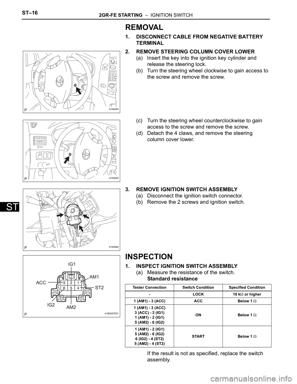
2. REMOVE STEERING COLUMN COVER LOWER
(a) Insert the key into the ignition key cylinder and
release the steering lock.
(b) Turn the steering wheel clockwise to gain access to
the screw and remove the screw.
(c) Turn the steering wheel counterclockwise to gain
access to the screw and remove the screw.
(d) Detach the 4 claws, and remove the steering
column cover lower.
3. REMOVE IGNITION SWITCH ASSEMBLY
(a) Disconnect the ignition switch connector.
(b) Remove the 2 screws and ignition switch.
INSPECTION
1. INSPECT IGNITION SWITCH ASSEMBLY
(a) Measure the resistance of the switch.
Standard resistance
If the result is not as specified, replace the switch
assembly.
A160244
A160245
A160246
A160247E01
Tester Connection Switch Condition Specified Condition
-LOCK10 k
or higher
1 (AM1) - 3 (ACC) ACC Below 1
1 (AM1) - 3 (ACC)
3 (ACC) - 2 (IG1)
1 (AM1) - 2 (IG1)
5 (AM2) - 6 (IG2)ON Below 1
1 (AM1) - 2 (IG1)
5 (AM2) - 6 (IG2)
6 (IG2) - 4 (ST2)
5 (AM2) - 4 (ST2)START Below 1
Page 1340 of 3000
2GR-FE STARTING – IGNITION SWITCHST–17
ST
INSTALLATION
1. INSTALL IGNITION SWITCH ASSEMBLY
(a) Install the ignition switch with the 2 screws.
(b) Install the ignition switch connector.
2. INSTALL STEERING COLUMN COVER LOWER
(a) Attach the 4 claws to install the steering column
cover lower.
(b) Insert the key into the ignition key cylinder and
release the steering lock.
(c) Turn the steering wheel counterclockwise and install
the screw.
(d) Turn the steering wheel clockwise and install the
screw.
3. CONNECT CABLE TO NEGATIVE BATTERY
TERMINAL
A160246
A160245
A160244
Page 1529 of 3000

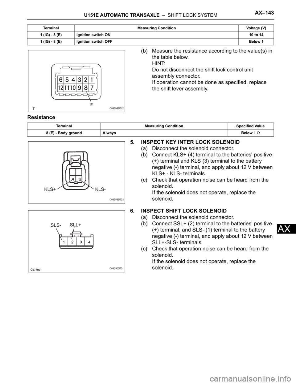
U151E AUTOMATIC TRANSAXLE – SHIFT LOCK SYSTEMAX–143
AX
(b) Measure the resistance according to the value(s) in
the table below.
HINT:
Do not disconnect the shift lock control unit
assembly connector.
If operation cannot be done as specified, replace
the shift lever assembly.
Resistance
5. INSPECT KEY INTER LOCK SOLENOID
(a) Disconnect the solenoid connector.
(b) Connect KLS+ (4) terminal to the batteries' positive
(+) terminal and KLS (3) terminal to the battery
negative (-) terminal, and apply about 12 V between
KLS+ - KLS- terminals.
(c) Check that operation noise can be heard from the
solenoid.
If the solenoid does not operate, replace the
solenoid.
6. INSPECT SHIFT LOCK SOLENOID
(a) Disconnect the solenoid connector.
(b) Connect SSL+ (2) terminal to the batteries' positive
(+) terminal, and SLS- (1) terminal to the battery
negative (-) terminal, and apply about 12 V between
SLL+-SLS- terminals.
(c) Check that operation noise can be heard from the
solenoid.
If the solenoid does not operate, replace the
solenoid.
1 (IG) - 8 (E) Ignition switch ON10 to 14
1 (IG) - 8 (E) Ignition switch OFFBelow 1 Terminal Measuring Condition Voltage (V)
C098999E12
Terminal Measuring Condition Specified Value
8 (E) - Body ground AlwaysBelow 1
D025589E02
D030503E01
Page 1832 of 3000

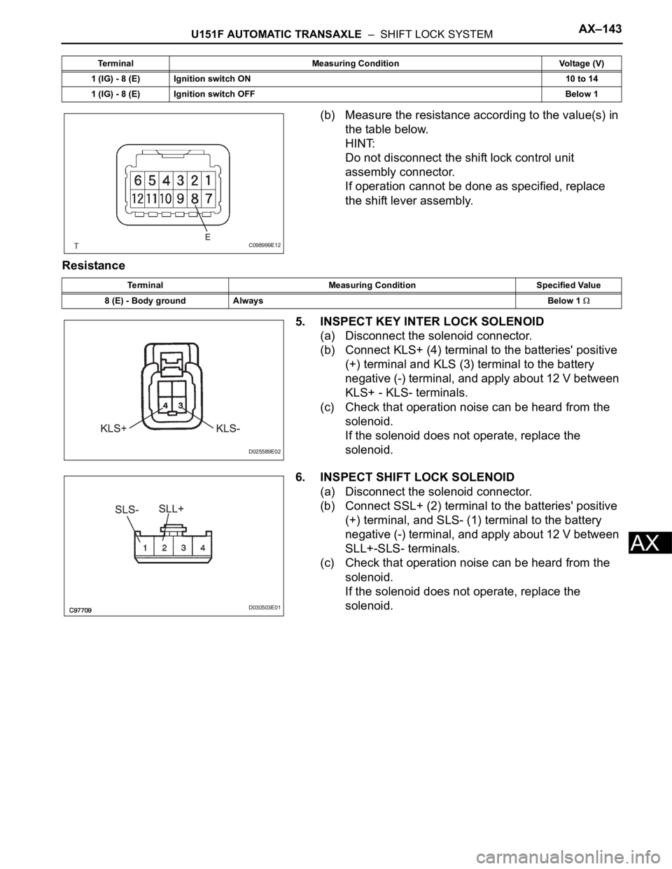
U151F AUTOMATIC TRANSAXLE – SHIFT LOCK SYSTEMAX–143
AX
(b) Measure the resistance according to the value(s) in
the table below.
HINT:
Do not disconnect the shift lock control unit
assembly connector.
If operation cannot be done as specified, replace
the shift lever assembly.
Resistance
5. INSPECT KEY INTER LOCK SOLENOID
(a) Disconnect the solenoid connector.
(b) Connect KLS+ (4) terminal to the batteries' positive
(+) terminal and KLS (3) terminal to the battery
negative (-) terminal, and apply about 12 V between
KLS+ - KLS- terminals.
(c) Check that operation noise can be heard from the
solenoid.
If the solenoid does not operate, replace the
solenoid.
6. INSPECT SHIFT LOCK SOLENOID
(a) Disconnect the solenoid connector.
(b) Connect SSL+ (2) terminal to the batteries' positive
(+) terminal, and SLS- (1) terminal to the battery
negative (-) terminal, and apply about 12 V between
SLL+-SLS- terminals.
(c) Check that operation noise can be heard from the
solenoid.
If the solenoid does not operate, replace the
solenoid.
1 (IG) - 8 (E) Ignition switch ON10 to 14
1 (IG) - 8 (E) Ignition switch OFFBelow 1 Terminal Measuring Condition Voltage (V)
C098999E12
Terminal Measuring Condition Specified Value
8 (E) - Body ground AlwaysBelow 1
D025589E02
D030503E01