Page 2795 of 3000

AC–52AIR CONDITIONING – AIR CONDITIONING SYSTEM (for Automatic Air Conditioning Sys-
tem)
AC
DESCRIPTION
This DTC is output when refrigerant pressure on the high pressure side is extremely low (0.19 MPa (2.0
kgf/cm
2, 28 psi) or less) or extremely high (3.14 MPa (32.0 kgf/cm2, 455 psi) or more). The pressure
sensor, which is installed on the pipe of the high pressure side to detect refrigerant pressure, outputs a
refrigerant pressure signal to the A/C amplifier. The A/C amplifier converts this signal to pressure
according to the sensor characteristics to control the compressor.
DTC B1423/23 Pressure Sensor Circuit
DTC No. DTC Detection Condition Trouble Area
B1423/23• Open or short in pressure sensor circuit
• Refrigerant pressure on the high pressure side is
extremely low (0.19 MPa (2.0 kgf/cm
2, 28 psi) or
less) or extremely high (3.14 MPa (32.0 kgf/cm2,
455 psi) or more).• Pressure sensor
• Harness or connector between pressure sensor
and A/C amplifier
• A/C amplifier
• Expansion valve (blocked, stuck)
• Condenser (blocked, deterioration of cooling
capacity due to dirt)
• Cooler dryer (moisture in the refrigerant cycle
cannot be absorbed)
• Cooling fan system (condenser cannot be cooled
down)
• A/C system (leaks, blocked)
Page 2804 of 3000
AIR CONDITIONING – AIR CONDITIONING SYSTEM (for Automatic Air Conditioning Sys-
tem)AC–61
AC
(c) Connect the three 1.5 V dry cell batteries' positive (+)
lead to terminal 3, and the negative (-) lead to terminal 1.
(d) Connect the voltmeter's positive (+) lead to terminal 2,
and the negative (-) lead to terminal 1.
(e) Measure the voltage according to the value(s) in the
table below.
Standard voltage
NG
OK
(a) Identify the area where refrigerant leaks from (See page
AC-173).
(b) Repair the identified area of the A/C system.
(c) Evacuate the A/C system.
NEXT
(a) Check if the cooling fan operates normally (See page
CO-4).
NG
E107326E13
Tester Connection Condition Specified Condition
2 - 1Refrigerant pressure:
0.39 to 3.187 MPa (57 to
463 psi)1.0 to 4.8 V
REPLACE A/C PRESSURE SENSOR
REPLACE A/C AMPLIFIER
12REPAIR A/C SYSTEM LEAK
CHARGE REFRIGERANT (See page AC-173)
13INSPECT COOLING FAN SYSTEM
REPAIR COOLING FAN SYSTEM
Page 2913 of 3000

AIR CONDITIONING – REFRIGERANTAC–169
AC
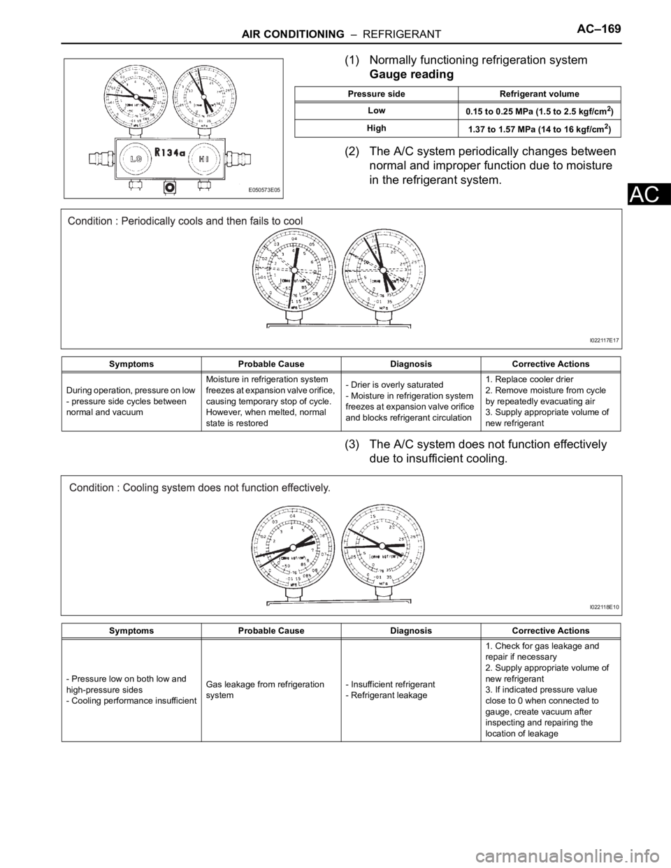
(1) Normally functioning refrigeration system
Gauge reading
(2) The A/C system periodically changes between
normal and improper function due to moisture
in the refrigerant system.
(3) The A/C system does not function effectively
due to insufficient cooling.
E050573E05
Pressure side Refrigerant volume
Low
0.15 to 0.25 MPa (1.5 to 2.5 kgf/cm
2)
High
1.37 to 1.57 MPa (14 to 16 kgf/cm
2)
Symptoms Probable Cause Diagnosis Corrective Actions
During operation, pressure on low
- pressure side cycles between
normal and vacuumMoisture in refrigeration system
freezes at expansion valve orifice,
causing temporary stop of cycle.
However, when melted, normal
state is restored- Drier is overly saturated
- Moisture in refrigeration system
freezes at expansion valve orifice
and blocks refrigerant circulation1. Replace cooler drier
2. Remove moisture from cycle
by repeatedly evacuating air
3. Supply appropriate volume of
new refrigerant
I022117E17
Symptoms Probable Cause Diagnosis Corrective Actions
- Pressure low on both low and
high-pressure sides
- Cooling performance insufficientGas leakage from refrigeration
system- Insufficient refrigerant
- Refrigerant leakage1. Check for gas leakage and
repair if necessary
2. Supply appropriate volume of
new refrigerant
3. If indicated pressure value
close to 0 when connected to
gauge, create vacuum after
inspecting and repairing the
location of leakage
I022118E10
Page 2914 of 3000

AC–170AIR CONDITIONING – REFRIGERANT
AC
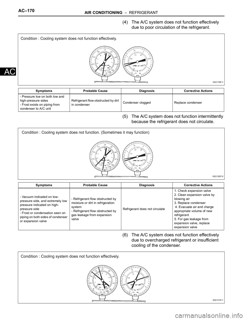
(4) The A/C system does not function effectively
due to poor circulation of the refrigerant.
(5) The A/C system does not function intermittently
because the refrigerant does not circulate.
(6) The A/C system does not function effectively
due to overcharged refrigerant or insufficient
cooling of the condenser.
Symptoms Probable Cause Diagnosis Corrective Actions
- Pressure low on both low and
high-pressure sides
- Frost exists on piping from
condenser to A/C unitRefrigerant flow obstructed by dirt
in condenserCondenser clogged Replace condenser
I022119E11
Symptoms Probable Cause Diagnosis Corrective Actions
- Vacuum indicated on low-
pressure side, and extremely low
pressure indicated on high-
pressure side
- Frost or condensation seen on
piping on both sides of condenser
or expansion valve- Refrigerant flow obstructed by
moisture or dirt in refrigeration
system
- Refrigerant flow obstructed by
gas leakage from expansion
valveRefrigerant does not circulate1. Check expansion valve
2. Clean expansion valve by
blowing air
3. Replace condenser
4. Evacuate air and charge
appropriate volume of new
refrigerant
5. For gas leakage from
expansion valve, replace
expansion valve
I022120E10
I022121E11
Page 2915 of 3000

AIR CONDITIONING – REFRIGERANTAC–171
AC
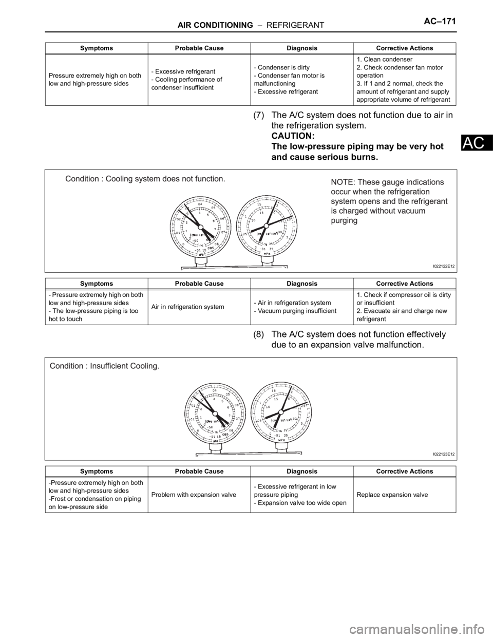
(7) The A/C system does not function due to air in
the refrigeration system.
CAUTION:
The low-pressure piping may be very hot
and cause serious burns.
(8) The A/C system does not function effectively
due to an expansion valve malfunction.
Symptoms Probable Cause Diagnosis Corrective Actions
Pressure extremely high on both
low and high-pressure sides- Excessive refrigerant
- Cooling performance of
condenser insufficient- Condenser is dirty
- Condenser fan motor is
malfunctioning
- Excessive refrigerant1. Clean condenser
2. Check condenser fan motor
operation
3. If 1 and 2 normal, check the
amount of refrigerant and supply
appropriate volume of refrigerant
Symptoms Probable Cause Diagnosis Corrective Actions
- Pressure extremely high on both
low and high-pressure sides
- The low-pressure piping is too
hot to touchAir in refrigeration system- Air in refrigeration system
- Vacuum purging insufficient1. Check if compressor oil is dirty
or insufficient
2. Evacuate air and charge new
refrigerant
I022122E12
Symptoms Probable Cause Diagnosis Corrective Actions
-Pressure extremely high on both
low and high-pressure sides
-Frost or condensation on piping
on low-pressure sideProblem with expansion valve- Excessive refrigerant in low
pressure piping
- Expansion valve too wide openReplace expansion valve
I022123E12
Page 2922 of 3000

AC–22AIR CONDITIONING – AIR CONDITIONING SYSTEM (for Automatic Air Conditioning Sys-
tem)
AC
B1422/22 Compressor Lock Sensor
Circuit1. A/C compressor (A/C
lock sensor)
2. Compressor drive belt
3. Harness or connector
between compressor and
magnetic clutch (A/C lock
sensor)
4. A/C amplifier
5. CAN communication
system
6. Multiplex
communication system
(BEAN)-AC-47
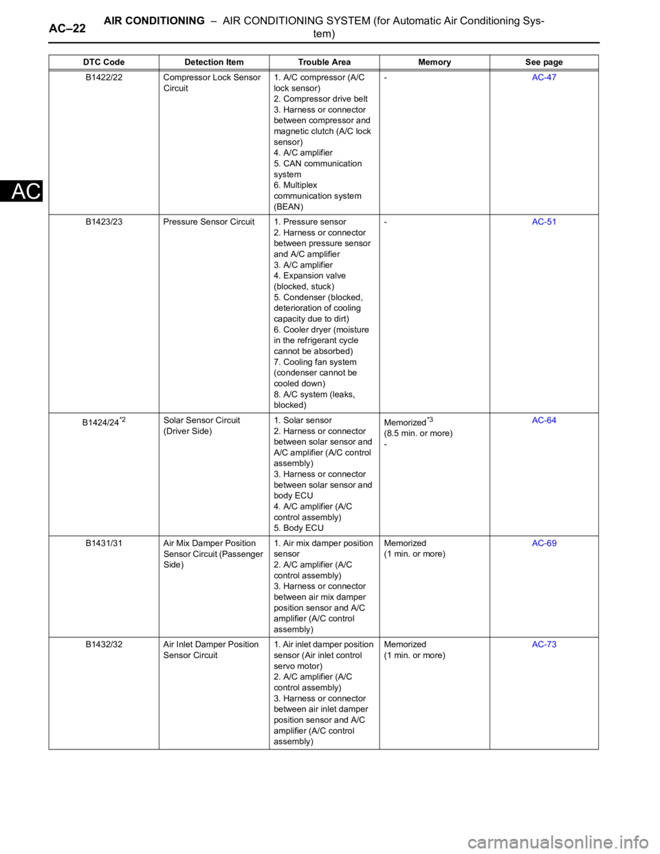
B1423/23 Pressure Sensor Circuit 1. Pressure sensor
2. Harness or connector
between pressure sensor
and A/C amplifier
3. A/C amplifier
4. Expansion valve
(blocked, stuck)
5. Condenser (blocked,
deterioration of cooling
capacity due to dirt)
6. Cooler dryer (moisture
in the refrigerant cycle
cannot be absorbed)
7. Cooling fan system
(condenser cannot be
cooled down)
8. A/C system (leaks,
blocked)-AC-51
B1424/24
*2Solar Sensor Circuit
(Driver Side)1. Solar sensor
2. Harness or connector
between solar sensor and
A/C amplifier (A/C control
assembly)
3. Harness or connector
between solar sensor and
body ECU
4. A/C amplifier (A/C
control assembly)
5. Body ECUMemorized*3
(8.5 min. or more)
-AC-64
B1431/31 Air Mix Damper Position
Sensor Circuit (Passenger
Side)1. Air mix damper position
sensor
2. A/C amplifier (A/C
control assembly)
3. Harness or connector
between air mix damper
position sensor and A/C
amplifier (A/C control
assembly)Memorized
(1 min. or more)AC-69
B1432/32 Air Inlet Damper Position
Sensor Circuit1. Air inlet damper position
sensor (Air inlet control
servo motor)
2. A/C amplifier (A/C
control assembly)
3. Harness or connector
between air inlet damper
position sensor and A/C
amplifier (A/C control
assembly)Memorized
(1 min. or more)AC-73 DTC Code Detection Item Trouble Area Memory See page
Page 2944 of 3000
AC–206AIR CONDITIONING – BLOWER UNIT (for Rear Air Conditioning System)
AC
DISASSEMBLY
1. REMOVE COOLER THERMISTOR NO.1 (for
Automatic Air Conditioning System)
(a) Disengage the 2 claw fittings and the clamp and
remove the cooler thermistor No. 1.
2. REMOVE COOLING UNIT MOTOR SUB-ASSEMBLY
WITH FAN
(a) Remove the 3 screws and the cooling unit motor
sub-assembly w/ fan.
3. REMOVE BLOWER RESISTOR TRANSISTOR
ASSEMBLY
(a) Remove the 2 screws and the blower resistor
transistor assembly.
4. REMOVE HEATER RADIATOR UNIT SUB-ASSEMBLY
(a) Disengage the claw fitting and remove the 3 screws
and blower case.
(b) Remove the 2 screws and the 2 clamps.
I035490E01
I044285
I035492
I035497E01
E055396
Page 2954 of 3000
AIR CONDITIONING – BLOWER MOTOR (for Rear Air Conditioning System)AC–211
AC
BLOWER MOTOR (for Rear Air
Conditioning System)
ON-VEHICLE INSPECTION
1. INSPECT COOLING UNIT MOTOR SUB-ASSEMBLY
WITH FAN
(a) Connect the positive (+) lead from the battery to
terminal 1 and negative (-) to terminal 2, then check
that the motor operates smoothly.
If operation is not as specified, replace the rear
blower motor.
E147480E02