Page 3152 of 5883
FAX-18
< DISASSEMBLY AND ASSEMBLY >
FRONT DRIVE SHAFT
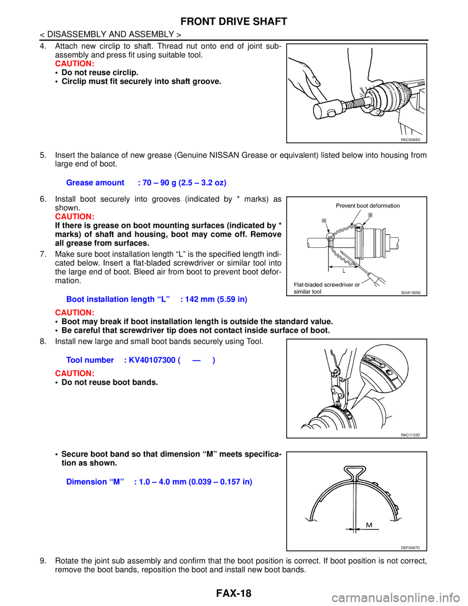
4. Attach new circlip to shaft. Thread nut onto end of joint sub-
assembly and press fit using suitable tool.
CAUTION:
Do not reuse circlip.
Circlip must fit securely into shaft groove.
5. Insert the balance of new grease (Genuine NISSAN Grease or equivalent) listed below into housing from
large end of boot.
6. Install boot securely into grooves (indicated by * marks) as
shown.
CAUTION:
If there is grease on boot mounting surfaces (indicated by *
marks) of shaft and housing, boot may come off. Remove
all grease from surfaces.
7. Make sure boot installation length “L” is the specified length indi-
cated below. Insert a flat-bladed screwdriver or similar tool into
the large end of boot. Bleed air from boot to prevent boot defor-
mation.
CAUTION:
Boot may break if boot installation length is outside the standard value.
Be careful that screwdriver tip does not contact inside surface of boot.
8. Install new large and small boot bands securely using Tool.
CAUTION:
Do not reuse boot bands.
Secure boot band so that dimension “M” meets specifica-
tion as shown.
9. Rotate the joint sub assembly and confirm that the boot position is correct. If boot position is not correct,
remove the boot bands, reposition the boot and install new boot bands.
RAC0049D
Grease amount : 70 – 90 g (2.5 – 3.2 oz)
Boot installation length “L” : 142 mm (5.59 in)
Tool number : KV40107300 ( — )
SDIA1505E
RAC1133D
Dimension “M” : 1.0 – 4.0 mm (0.039 – 0.157 in)
DSF0047D
Page 3156 of 5883
FAX-22
< DISASSEMBLY AND ASSEMBLY >
FRONT DRIVE SHAFT
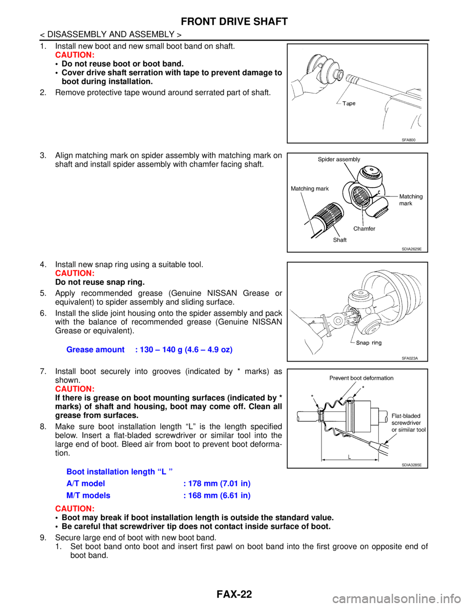
1. Install new boot and new small boot band on shaft.
CAUTION:
Do not reuse boot or boot band.
Cover drive shaft serration with tape to prevent damage to
boot during installation.
2. Remove protective tape wound around serrated part of shaft.
3. Align matching mark on spider assembly with matching mark on
shaft and install spider assembly with chamfer facing shaft.
4. Install new snap ring using a suitable tool.
CAUTION:
Do not reuse snap ring.
5. Apply recommended grease (Genuine NISSAN Grease or
equivalent) to spider assembly and sliding surface.
6. Install the slide joint housing onto the spider assembly and pack
with the balance of recommended grease (Genuine NISSAN
Grease or equivalent).
7. Install boot securely into grooves (indicated by * marks) as
shown.
CAUTION:
If there is grease on boot mounting surfaces (indicated by *
marks) of shaft and housing, boot may come off. Clean all
grease from surfaces.
8. Make sure boot installation length “L” is the length specified
below. Insert a flat-bladed screwdriver or similar tool into the
large end of boot. Bleed air from boot to prevent boot deforma-
tion.
CAUTION:
Boot may break if boot installation length is outside the standard value.
Be careful that screwdriver tip does not contact inside surface of boot.
9. Secure large end of boot with new boot band.
1. Set boot band onto boot and insert first pawl on boot band into the first groove on opposite end of
boot band.
SFA800
SDIA2629E
Grease amount : 130 – 140 g (4.6 – 4.9 oz) SFA023A
Boot installation length “L ”
A/T model : 178 mm (7.01 in)
M/T models : 168 mm (6.61 in)
SDIA3285E
Page 3158 of 5883
FAX-24
< DISASSEMBLY AND ASSEMBLY >
FRONT DRIVE SHAFT
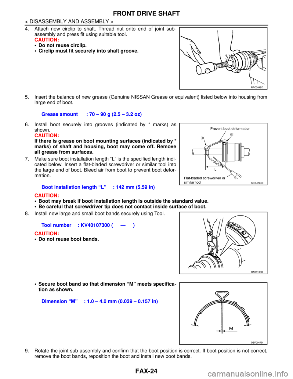
4. Attach new circlip to shaft. Thread nut onto end of joint sub-
assembly and press fit using suitable tool.
CAUTION:
Do not reuse circlip.
Circlip must fit securely into shaft groove.
5. Insert the balance of new grease (Genuine NISSAN Grease or equivalent) listed below into housing from
large end of boot.
6. Install boot securely into grooves (indicated by * marks) as
shown.
CAUTION:
If there is grease on boot mounting surfaces (indicated by *
marks) of shaft and housing, boot may come off. Remove
all grease from surfaces.
7. Make sure boot installation length “L” is the specified length indi-
cated below. Insert a flat-bladed screwdriver or similar tool into
the large end of boot. Bleed air from boot to prevent boot defor-
mation.
CAUTION:
Boot may break if boot installation length is outside the standard value.
Be careful that screwdriver tip does not contact inside surface of boot.
8. Install new large and small boot bands securely using Tool.
CAUTION:
Do not reuse boot bands.
Secure boot band so that dimension “M” meets specifica-
tion as shown.
9. Rotate the joint sub assembly and confirm that the boot position is correct. If boot position is not correct,
remove the boot bands, reposition the boot and install new boot bands.
RAC0049D
Grease amount : 70 – 90 g (2.5 – 3.2 oz)
Boot installation length “L” : 142 mm (5.59 in)
Tool number : KV40107300 ( — )
SDIA1505E
RAC1133D
Dimension “M” : 1.0 – 4.0 mm (0.039 – 0.157 in)
DSF0047D
Page 3160 of 5883
FAX-26
< SERVICE DATA AND SPECIFICATIONS (SDS)
SERVICE DATA AND SPECIFICATIONS (SDS)
SERVICE DATA AND SPECIFICATIONS (SDS)
SERVICE DATA AND SPECIFICATIONS (SDS)
Drive ShaftINFOID:0000000001716805
Dynamic DamperINFOID:0000000001716806
Joint type Wheel side Transaxle side
Grease quantity 70 - 90 g (2.5 - 3.2 oz) 130 - 140 g (4.6 - 4.9 oz)
Boots installed lengthLeft side
142 mm (5.59 in)176 mm (6.93 in) (A/T model)
181.2 mm (7.13 in) (M/T models)
Right side178 mm (7.01 in) (A/T model)
168 mm (6.61 in) (M/T models)
Dimension A230 – 236 mm (9.06 – 9.29 in)
Dimension B70 mm (2.76 in)
FAC0156D
Page 3172 of 5883
FL-12
< ON-VEHICLE REPAIR >
FUEL TANK
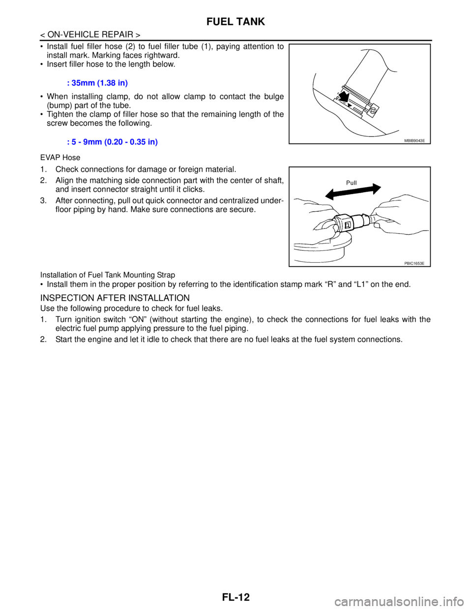
Install fuel filler hose (2) to fuel filler tube (1), paying attention to
install mark. Marking faces rightward.
Insert filler hose to the length below.
When installing clamp, do not allow clamp to contact the bulge
(bump) part of the tube.
Tighten the clamp of filler hose so that the remaining length of the
screw becomes the following.
EVAP Hose
1. Check connections for damage or foreign material.
2. Align the matching side connection part with the center of shaft,
and insert connector straight until it clicks.
3. After connecting, pull out quick connector and centralized under-
floor piping by hand. Make sure connections are secure.
Installation of Fuel Tank Mounting Strap
Install them in the proper position by referring to the identification stamp mark “R” and “L1” on the end.
INSPECTION AFTER INSTALLATION
Use the following procedure to check for fuel leaks.
1. Turn ignition switch “ON” (without starting the engine), to check the connections for fuel leaks with the
electric fuel pump applying pressure to the fuel piping.
2. Start the engine and let it idle to check that there are no fuel leaks at the fuel system connections. : 35mm (1.38 in)
: 5 - 9mm (0.20 - 0.35 in)
MBIB9043E
PBIC1653E
Page 3175 of 5883
FUEL TANK
FL-15
< ON-VEHICLE REPAIR >
C
D
E
F
G
H
I
J
K
L
MA
FL
N
P O
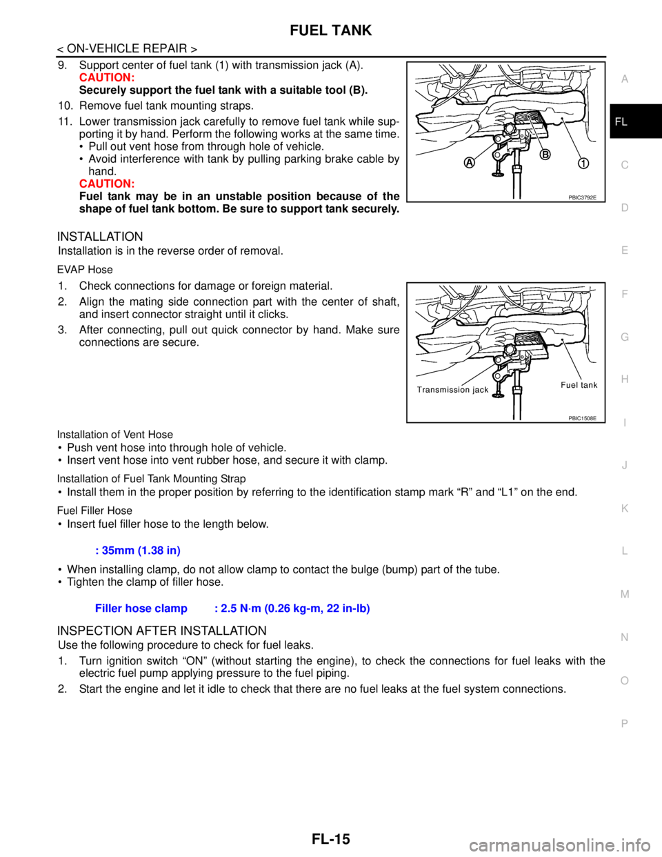
9. Support center of fuel tank (1) with transmission jack (A).
CAUTION:
Securely support the fuel tank with a suitable tool (B).
10. Remove fuel tank mounting straps.
11. Lower transmission jack carefully to remove fuel tank while sup-
porting it by hand. Perform the following works at the same time.
Pull out vent hose from through hole of vehicle.
Avoid interference with tank by pulling parking brake cable by
hand.
CAUTION:
Fuel tank may be in an unstable position because of the
shape of fuel tank bottom. Be sure to support tank securely.
INSTALLATION
Installation is in the reverse order of removal.
EVAP Hose
1. Check connections for damage or foreign material.
2. Align the mating side connection part with the center of shaft,
and insert connector straight until it clicks.
3. After connecting, pull out quick connector by hand. Make sure
connections are secure.
Installation of Vent Hose
Push vent hose into through hole of vehicle.
Insert vent hose into vent rubber hose, and secure it with clamp.
Installation of Fuel Tank Mounting Strap
Install them in the proper position by referring to the identification stamp mark “R” and “L1” on the end.
Fuel Filler Hose
Insert fuel filler hose to the length below.
When installing clamp, do not allow clamp to contact the bulge (bump) part of the tube.
Tighten the clamp of filler hose.
INSPECTION AFTER INSTALLATION
Use the following procedure to check for fuel leaks.
1. Turn ignition switch “ON” (without starting the engine), to check the connections for fuel leaks with the
electric fuel pump applying pressure to the fuel piping.
2. Start the engine and let it idle to check that there are no fuel leaks at the fuel system connections.
PBIC3792E
PBIC1508E
: 35mm (1.38 in)
Filler hose clamp : 2.5 N·m (0.26 kg-m, 22 in-lb)
Page 3184 of 5883
FSU-8
< ON-VEHICLE MAINTENANCE >
FRONT SUSPENSION ASSEMBLY
3. Put a mark on base line of the tread (rear side) of both tires at
the same height of hub center. These are measuring points.
4. Measure distance “A” (rear side).
5. Push vehicle slowly ahead to rotate wheels 180 degrees (1/2
turn).
CAUTION:
If wheels have rotated more than 180 degrees (1/2 turn), try
the above procedure again from the beginning. Never push
vehicle backward.
6. Measure distance “B” (front side).
7. Use the formula below to calculate total toe-in.
If the total toe-in is outside the specification, adjust toe-in by varying the length of between steering
outer socket and inner socket.
AFA050
SFA234AC
Total toe-in = A - B
For total toe-in specification, refer to FSU-17, "
Wheel Alignment (Unladen*)" .
Page 3235 of 5883
IDENTIFICATION INFORMATION
GI-41
< FEATURES OF NEW MODEL >
C
D
E
F
G
H
I
J
K
L
MB
GI
N
O
P
HR1.6 L
K9K (1.5 DCI)
AUTOMATIC TRANSAXLE NUMBER
MANUAL TRANSAXLE NUMBER
DimensionsINFOID:0000000001606152
Unit: mm (in)
ALAIA0002ZZ
ALAIA0003ZZ
SGI113A
PCIB1612E
Overall length Hatchback: 4,295 (169.1) Sedan: 4470 (176)
Overall width1,694.2 (66.7)
Overall height1,534.1 (60.4)
Front tread1,480 (58.3)