Page 17 of 134
TROUBLE DIAGNOSIS
BRC-17
[ABS]
C
D
E
G
H
I
J
K
L
MA
B
BRC
Revision: 2006 November2007 350Z
TFWT0046E
Page 18 of 134
![NISSAN 350Z 2007 Z33 Brake Control System Workshop Manual BRC-18
[ABS]
TROUBLE DIAGNOSIS
Revision: 2006 November2007 350Z
Control Unit Input/Output Signal StandardNFS00022
REFERENCE VALUE FROM CONSULT-III
CAUTION:
The display shows the control unit calculati](/manual-img/5/758/w960_758-17.png "NISSAN 350Z 2007 Z33 Brake Control System Workshop Manual BRC-18
[ABS]
TROUBLE DIAGNOSIS
Revision: 2006 November2007 350Z
Control Unit Input/Output Signal StandardNFS00022
REFERENCE VALUE FROM CONSULT-III
CAUTION:
The display shows the control unit calculati")
BRC-18
[ABS]
TROUBLE DIAGNOSIS
Revision: 2006 November2007 350Z
Control Unit Input/Output Signal StandardNFS00022
REFERENCE VALUE FROM CONSULT-III
CAUTION:
The display shows the control unit calculation data, so a normal value might be displayed even in the
event the output circuit (harness) is open or short - circuited.
Note 1: Confirm tire pressure is normal.
Note 2: Serves as EBD warning lamp.
Note 3: ON/OFF timing of ABS warning lamp
ON: For approximately 1 second after the ignition switch is turned on or when an error is detected.
OFF: Approximately 1 second after the ignition switch is turned on (when system is normal).Monitor item Display ContentData monitor
ConditionReference values for normal
operation
WHEEL SENSORWheel speed calculated using
signals from all four wheel sen-
sorsVehicle stopped 0 km/h (0 MPH)
While driving (Note 1)Nearly matches the speed-
ometer display
(± 10% or less)
IN ABS S/V
OUT ABS S/VOperation status of all solenoidsWhen the actuator solenoid operates or
during a fail-safeON
When the actuator relay operates and
the actuator solenoid does not operateOFF
EBD WARN LAMPBrake warning lamp on condition
(Note 2)Brake warning lamp ON ON
Brake warning lamp OFF OFF
STOP LAMP SW Brake pedal operationBrake pedal depressed ON
Brake pedal not depressed OFF
MOTOR RELAYMotor and motor relay operation
statusWhen the motor relay and motor are
operatingON
When the motor relay and motor are not
operatingOFF
ACTUATOR RLY Actuator relay operation statusWhen the actuator relay is operating OFF
When the actuator relay is not operat-
ingON
ABS WARN LAMPABS warning lamp on condition
(Note 3)ABS warning lamp ON ON
ABS warning lamp OFF OFF
BATTERY VOLTBattery voltage supplied to ABS
control unitIgnition switch ON 10 - 16V
GEARDetermined gear shift position
from the A/T PNP switch signalDrivingM/T vehicles are always left
in 1.
ENGINE RPM Engine runningWith engine stopped 0 rpm
With engine runningAlmost in accordance with
tachometer display
FAIL SIGNAL Fail signal statusDuring ABS fail-safe
During EBD fail-safeON
Page 19 of 134
![NISSAN 350Z 2007 Z33 Brake Control System Workshop Manual TROUBLE DIAGNOSIS
BRC-19
[ABS]
C
D
E
G
H
I
J
K
L
MA
B
BRC
Revision: 2006 November2007 350Z
CONSULT- II Functions (ABS)NFS00023
CONSULT-III MAIN FUNCTION
CONSULT-III can display each diagnostic item u](/manual-img/5/758/w960_758-18.png "NISSAN 350Z 2007 Z33 Brake Control System Workshop Manual TROUBLE DIAGNOSIS
BRC-19
[ABS]
C
D
E
G
H
I
J
K
L
MA
B
BRC
Revision: 2006 November2007 350Z
CONSULT- II Functions (ABS)NFS00023
CONSULT-III MAIN FUNCTION
CONSULT-III can display each diagnostic item u")
TROUBLE DIAGNOSIS
BRC-19
[ABS]
C
D
E
G
H
I
J
K
L
MA
B
BRC
Revision: 2006 November2007 350Z
CONSULT- II Functions (ABS)NFS00023
CONSULT-III MAIN FUNCTION
CONSULT-III can display each diagnostic item using the diagnostic test modes shown following.
Self-DiagnosisNFS000HD
OPERATION PROCEDURE
1. Before performing the self-diagnosis, start engine and drive vehicle at 30 km/h (19 MPH) or more for
approximately 1 minute.
HOW TO ERASE SELF-DIAGNOSIS RESULTS
1. After erasing DTC memory, start engine and drive vehicle at 30 km/h (19 MPH) or more for approximately
1 minute as the final inspection, and make sure that the ABS warning lamp and brake warning lamp turn
OFF.
CAUTION:
If memory cannot be erased, perform applicably diagnosis.
�When the wheel sensor malfunctions, after inspecting the wheel sensor system, the ABS warning lamp
and brake warning lamp will not turn OFF even when the system is normal unless the vehicle is driving
at approximately 30 km/h (19 MPH) or more for approximately 1 minute.
�Brake warning lamp will turn ON in case of parking brake operation (when switch is ON) or of brake
fluid level switch operation (when brake fluid is insufficient).
Diagnostic test mode Function Reference
SELF-DIAG RESULTS Self-diagnostic results can be read and erased quickly.BRC-19, "
Self-Diagnosis"
DATA MONITORInput/Output data in the ABS actuator and electric unit (control unit) can be
read.BRC-21, "Data Monitor"
CAN DIAG SUPPORT
MNTRThe results of transmit/receive diagnosis of communication can be read.LAN-44, "CAN Diagnostic
Support Monitor"
ACTIVE TESTDiagnostic Test Mode in which CONSULT-III drives some actuators apart
from the ABS actuator and electric unit (control unit) and also shifts some
parameters in a specified range.BRC-22, "Active Test"
FUNCTION TESTConducted by CONSULT-III instead of a technician to determine whether
each system is “OK” or “NG”.—
ECU PART NUMBER ABS actuator and electric unit (control unit) part number can be read. —
Page 20 of 134
![NISSAN 350Z 2007 Z33 Brake Control System Workshop Manual BRC-20
[ABS]
TROUBLE DIAGNOSIS
Revision: 2006 November2007 350Z
DISPLAY ITEM LIST
Display item Malfunction detecting condition Check item
RR RH SENSOR-1
[C1101]When the circuit in the rear RH wheel se](/manual-img/5/758/w960_758-19.png "NISSAN 350Z 2007 Z33 Brake Control System Workshop Manual BRC-20
[ABS]
TROUBLE DIAGNOSIS
Revision: 2006 November2007 350Z
DISPLAY ITEM LIST
Display item Malfunction detecting condition Check item
RR RH SENSOR-1
[C1101]When the circuit in the rear RH wheel se")
BRC-20
[ABS]
TROUBLE DIAGNOSIS
Revision: 2006 November2007 350Z
DISPLAY ITEM LIST
Display item Malfunction detecting condition Check item
RR RH SENSOR-1
[C1101]When the circuit in the rear RH wheel sensor is open.
BRC-25, "
Wheel
Sensor System"
(Note 1) RR LH SENSOR-1
[C1102]When the circuit in the rear LH wheel sensor is open.
FR RH SENSOR-1
[C1103]When the circuit in the front RH wheel sensor is open.
FR LH SENSOR-1
[C1104]When the circuit in the front LH wheel sensor is open.
RR RH SENSOR-2
[C1105]When the circuit in the rear RH wheel sensor is short-circuited. Or when the
sensor power voltage is outside the standard. When the distance between the
wheel sensor and sensor rotor is too large and the sensor pulse cannot be
recognized by the control unit.
RR LH SENSOR-2
[C1106]When the circuit in the rear LH wheel sensor is short-circuited. Or when the
sensor power voltage is outside the standard. When the distance between the
wheel sensor and sensor rotor is too large and the sensor pulse cannot be
recognized by the control unit.
FR RH SENSOR-2
[C1107]When the circuit in the front RH wheel sensor is short-circuited. Or when the
sensor power voltage is outside the standard. When the distance between the
wheel sensor and sensor rotor is too large and the sensor pulse cannot be
recognized by the control unit.
FR LH SENSOR-2
[C1108]When the circuit in the front LH wheel sensor is short-circuited. Or when the
sensor power voltage is outside the standard. When the distance between the
wheel sensor and sensor rotor is too large and the sensor pulse cannot be
recognized by the control unit.
BATTERY VOLTAGE
[ABNORMAL]
[C1109]When the ABS actuator and electric unit (control unit) power supply voltage is
lower than normal.BRC-27, "
ABS Actua-
tor and Electric Unit
(Control Unit) Power
and Ground Sys-
tems"
CONTROLLER FAILURE
[ C 111 0 ]When there is an internal malfunction in the ABS actuator and electric unit
(control unit).BRC-27, "ABS Actua-
tor and Electric Unit
(Control Unit)"
MAIN RELAY
[ C 111 4 ]When the control unit detects an error in the actuator relay system.BRC-29, "
ABS Actua-
tor Relay or ABS
Motor Relay Power
System"
STOP LAMP SW
[ C 111 6 ]When a stop lamp switch open-circuit is detected.BRC-30, "Stop Lamp
Switch System"
FR LH IN ABS SOL
[C1120]When the control unit detects an error in the front left inlet solenoid system.
BRC-29, "
ABS Actua-
tor Relay or ABS
Motor Relay Power
System"
FR LH OUT ABS SOL
[C1121]When the control unit detects an error in the front left outlet solenoid system.
FR RH IN ABS SOL
[C1122]When the control unit detects an error in the front right inlet solenoid system.
FR RH OUT ABS SOL
[C1123]When the control unit detects an error in the front right outlet solenoid system.
RR LH IN ABS SOL
[C1124]When the control unit detects an error in the rear left inlet solenoid system.
RR LH OUT ABS SOL
[C1125]When the control unit detects an error in the rear left outlet solenoid system.
RR RH IN ABS SOL
[C1126]When the control unit detects an error in the rear right inlet solenoid system.
RR RH OUT ABS SOL
[C1127]When the control unit detects an error in the rear right outlet solenoid system.
Page 21 of 134
![NISSAN 350Z 2007 Z33 Brake Control System Workshop Manual TROUBLE DIAGNOSIS
BRC-21
[ABS]
C
D
E
G
H
I
J
K
L
MA
B
BRC
Revision: 2006 November2007 350Z
Note 1: After completing repairs of the shorted sensor circuit, when ignition switch is turned ON, ABS warnin](/manual-img/5/758/w960_758-20.png "NISSAN 350Z 2007 Z33 Brake Control System Workshop Manual TROUBLE DIAGNOSIS
BRC-21
[ABS]
C
D
E
G
H
I
J
K
L
MA
B
BRC
Revision: 2006 November2007 350Z
Note 1: After completing repairs of the shorted sensor circuit, when ignition switch is turned ON, ABS warnin")
TROUBLE DIAGNOSIS
BRC-21
[ABS]
C
D
E
G
H
I
J
K
L
MA
B
BRC
Revision: 2006 November2007 350Z
Note 1: After completing repairs of the shorted sensor circuit, when ignition switch is turned ON, ABS warning lamp turns on. Check that
ABS warning lamp turns off while driving the vehicle at approximately 30 km/h (19 MPH) or more for approximately 1 minute according
to self-diagnosis procedure. In addition, if wheel sensor 2 is displayed for the wheels, check the wheel sensor circuit and also check the
control unit power voltage.
Note 2: When errors are detected in several systems, including the CAN communication system [U1000], troubleshoot the CAN commu-
nication system.
Data MonitorNFS000HE
DISPLAY ITEM LIST
×: Standard –: Not applicable : Option EMERGENCY BRAKE
[C1153]When the ABS actuator and electric unit (control unit) malfunctions (pressure
increase is too much or too little).BRC-31, "
ABS Actua-
tor and Electric Unit
(Control Unit) 2"
CAN COMM CIRCUIT
[U1000]When ABS actuator and electric unit (control unit) is not transmitting or receiv-
ing CAN communication signal for 2 seconds or more.BRC-31, "CAN Com-
munication System"
(Note 2) Display item Malfunction detecting condition Check item
Item (Unit)SELECT MONITOR ITEM
Remarks
ECM INPUT
SIGNALSMAIN SIGNALSSELECTION
MENU
FR LH SENSOR
[km/h (MPH)]××Wheel speed calculated by front LH wheel sensor sig-
nal is displayed.
FR RH SENSOR
[km/h (MPH)]××Wheel speed calculated by front RH wheel sensor sig-
nal is displayed.
RR LH SENSOR
[km/h (MPH)]××Wheel speed calculated by rear LH wheel sensor signal
is displayed.
RR RH SENSOR
[km/h (MPH)]××Wheel speed calculated by rear RH wheel sensor sig-
nal is displayed.
FR LH IN SOL
(ON/OFF)—×Front left inlet ABS solenoid valve (ON/OFF) status is
displayed.
FR LH OUT SOL
(ON/OFF)—×Front left outlet ABS solenoid valve (ON/OFF) status is
displayed.
RR RH IN SOL
(ON/OFF)—×Rear right inlet ABS solenoid valve (ON/OFF) status is
displayed.
RR RH OUT SOL
(ON/OFF)—×Rear right outlet ABS solenoid valve (ON/OFF) status
is displayed.
FR RH IN SOL
(ON/OFF)—×Front right inlet ABS solenoid valve (ON/OFF) status is
displayed.
FR RH OUT SOL
(ON/OFF)—×Front right outlet ABS solenoid valve (ON/OFF) status
is displayed.
RR LH IN SOL
(ON/OFF)—×Rear left wheel inside ABS solenoid valve (ON/OFF)
status is displayed.
RR LH OUT SOL
(ON/OFF)—×Rear left outlet ABS solenoid valve (ON/OFF) status is
displayed.
EBD WARN LAMP
(ON/OFF)—×Brake warning lamp (ON/OFF) status is displayed.
STOP LAMP SW
(ON/OFF)××Stop lamp switch (ON/OFF) status is displayed.
MOTOR RELAY
(ON/OFF)—×ABS motor relay (ON/OFF) condition is displayed.
ACTUATOR RLY
(ON/OFF)—×ABS actuator relay (ON/OFF) status is displayed.
ABS WARN LAMP
(ON/OFF)—×ABS warning lamp (ON/OFF) status is displayed.
BATTERY VOLT
(V )××The voltage supplied to the ABS control unit is dis-
played.
Page 22 of 134
![NISSAN 350Z 2007 Z33 Brake Control System Workshop Manual BRC-22
[ABS]
TROUBLE DIAGNOSIS
Revision: 2006 November2007 350Z
Active TestNFS000IN
CAUTION:
�Do not perform active test while driving.
�Make sure to completely bleed air from the brake system.
�The A](/manual-img/5/758/w960_758-21.png "NISSAN 350Z 2007 Z33 Brake Control System Workshop Manual BRC-22
[ABS]
TROUBLE DIAGNOSIS
Revision: 2006 November2007 350Z
Active TestNFS000IN
CAUTION:
�Do not perform active test while driving.
�Make sure to completely bleed air from the brake system.
�The A")
BRC-22
[ABS]
TROUBLE DIAGNOSIS
Revision: 2006 November2007 350Z
Active TestNFS000IN
CAUTION:
�Do not perform active test while driving.
�Make sure to completely bleed air from the brake system.
�The ABS and brake warning lamps turn on during the active test.
NOTE:
�When the active test is conducted while depressing the pedal, the pedal depression amount will change,
but this is normal.
�Approximately 10 seconds after the operation is begun, “TEST STOP” will be displayed.
TEST ITEM
Solenoid valve
CAUTION:
The example shown is for the front right wheel. The procedure for the other wheels is the same as
given below.
For ABS solenoid valve, touch “UP”, “KEEP”, and “DOWN”.Then use screen monitor to check that solenoid
valve operates as shown in the table below.
*: ON for 1 to 2 seconds after the touch, and then OFF
ABS Motor
Touch “ON”, “OFF” on the display screen and make sure the ABS motor relay is operating as shown in the
table below.
EBD SIGNAL
(ON/OFF)— — EBD operation (ON/OFF) status is displayed.
ABS SIGNAL
(ON/OFF)— — ABS operation (ON/OFF) status is displayed.
EBD FAIL SIG
(ON/OFF)— — EBD fail-safe signal (ON/OFF) status is displayed.
ABS FAIL SIG
(ON/OFF)— — ABS fail-safe signal (ON/OFF) status is displayed. Item (Unit)SELECT MONITOR ITEM
Remarks
ECM INPUT
SIGNALSMAIN SIGNALSSELECTION
MENU
OperationABS solenoid valve
UP KEEP DOWN
FR RH IN SOL OFF ON ON
FR RH OUT SOL OFF OFF ON*
Operation ON OFF
MOTOR RELAY ON OFF
ACTUATOR RLY ON ON
Page 23 of 134
![NISSAN 350Z 2007 Z33 Brake Control System Workshop Manual TROUBLE DIAGNOSIS
BRC-23
[ABS]
C
D
E
G
H
I
J
K
L
MA
B
BRC
Revision: 2006 November2007 350Z
Correct and Quick DiagnosisNFS00024
DIAGNOSIS PRECAUTIONS
�Before performing the trouble diagnosis, always re](/manual-img/5/758/w960_758-22.png "NISSAN 350Z 2007 Z33 Brake Control System Workshop Manual TROUBLE DIAGNOSIS
BRC-23
[ABS]
C
D
E
G
H
I
J
K
L
MA
B
BRC
Revision: 2006 November2007 350Z
Correct and Quick DiagnosisNFS00024
DIAGNOSIS PRECAUTIONS
�Before performing the trouble diagnosis, always re")
TROUBLE DIAGNOSIS
BRC-23
[ABS]
C
D
E
G
H
I
J
K
L
MA
B
BRC
Revision: 2006 November2007 350Z
Correct and Quick DiagnosisNFS00024
DIAGNOSIS PRECAUTIONS
�Before performing the trouble diagnosis, always read the general information (GI) to confirm the general
precautions. Refer to GI-3, "
General Precautions" .
�After completing service, always erase the self-diagnosis results. Refer to BRC-19, "HOW TO ERASE
SELF-DIAGNOSIS RESULTS" .
�When inspection of the continuity or voltage between units is performed, check connector terminals for
disconnection, looseness, bend, or collapse. If any non-standard condition is detected, repair or replace
applicable part.
�Intermittent errors may be caused by a poor connection in the harness, connector, or terminal. Move har-
nesses, harness connectors, or terminals by hand to make sure all connections are solid and undamaged.
�If a circuit tester is used for the check, be careful not to forcibly extend any connector terminal.
�ABS is a system that uses electronic control to perform brake control and engine power control. There-
fore, phenomena like those shown in the following table may occur, but this is because the system is
working normally.
ABS WARNING LAMP ON/OFF TIMING
×: ON –: OFF
Basic InspectionNFS00025
BRAKE FLUID AMOUNT, LEAKS, AND BRAKE PADS INSPECTION
1. Check fluid level in the brake reservoir tank. If fluid level is low, refill the brake fluid.
2. Check brake tubes or hoses and around ABS actuator for leaks. If there is leaking or oozing fluid, check
following items.
�If ABS actuator connection is loose, tighten the piping to the specified torque and re-conduct the leak
inspection to make sure there are no leaks.
� If there is damage to the connection flare nut or ABS actuator screw, replace the damaged part and re-
conduct the leak inspection to make sure there are no leaks.
�When there is fluid leaking or oozing from a part other than ABS actuator connection, if the fluid is just
oozing out, use a clean cloth to wipe off the oozing fluid and re-check for leaks. If fluid is still oozing out,
replace the damaged part.
�When there is fluid leaking or oozing at ABS actuator, if the fluid is just oozing out, use a clean cloth to
wipe off the oozing fluid and re-check for leaks. If fluid is still oozing out, replace ABS actuator body.
CAUTION:
ABS actuator and electric unit (control unit) cannot be disassembled.
3. Check brake pad degree of wear. Refer to BR-26, "
PAD WEAR INSPECTION" in “Front Disc Brake” and
BR-39, "
PAD WEAR INSPECTION" in “Rear Disc Brake”.
Symptom Symptom description Result
Motor operation noiseThis is the sound of the motor operating inside ABS actuator, and there
may be some low sounds while the ABS is operating.
Normal
Just after the engine starts, the motor operating noise may be heard. This
is a normal status of the system operation check.
System operation check noiseWhen the engine is started, you may barely be able to hear a slight thud-
ding sound from the engine room, but this sound is made by the system
operation check and is normal.Normal
ABS operation
(longer stopping distance)Stopping distance may be longer for vehicles with ABS when the vehicle
drives on rough or snow-covered roads. Use lower speeds when driving on
these kinds of roads.Normal
Condition ABS warning lamp Remarks
Ignition switch OFF — —
For approximately “1” second after ignition switch ON×—
After approximately “1” second after ignition switch ON.
(When system is normal)— Turns off 2 second after engine start
ABS error×When there is an ABS actuator and electric unit
error (power or ground error)
Page 24 of 134
BRC-24
[ABS]
TROUBLE DIAGNOSIS
Revision: 2006 November2007 350Z
POWER SYSTEM TERMINAL LOOSENESS AND BATTERY INSPECTION
Make sure the battery positive cable, negative cable and ground connection are not loose. In addition, check
the battery voltage to make sure it has not dropped.
ABS WARNING LAMP INSPECTION
1. Make sure ABS warning lamp turned on approximately 1 second when the ignition switch is turned ON.
Check CAN communications. Refer to BRC-31, "
CAN Communication System" .
2. Make sure lamp turns off approximately 1 second after the ignition switch is turned on. If the lamp does
not turn off, conduct self-diagnosis.
3. Make sure ABS warning lamp turn off 2 seconds after the engine is started. If ABS warning lamp has not
turned off 10 seconds after the engine has been started, conduct self-diagnosis of the ABS actuator and
electric unit.
4. After conducting the self-diagnosis, be sure to erase the error memory. Refer to BRC-19, "
HOW TO
ERASE SELF-DIAGNOSIS RESULTS"
 1
1 2
2 3
3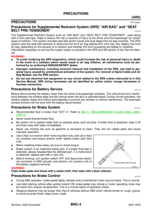 4
4 5
5 6
6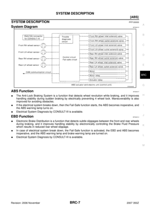 7
7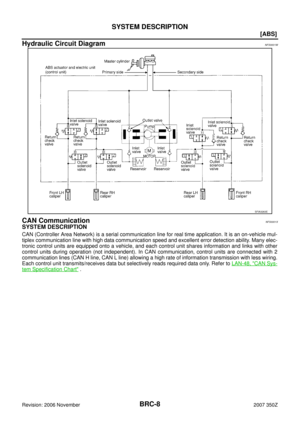 8
8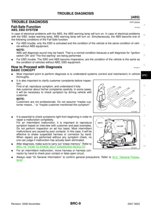 9
9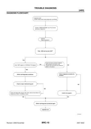 10
10 11
11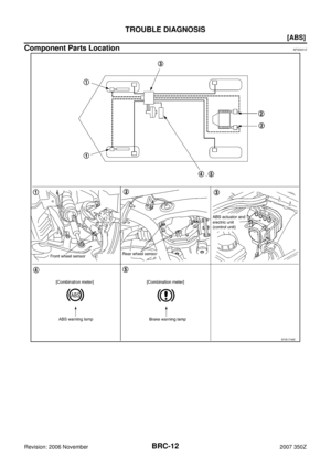 12
12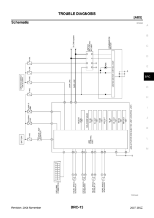 13
13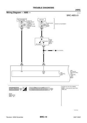 14
14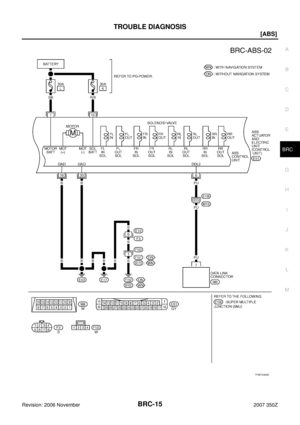 15
15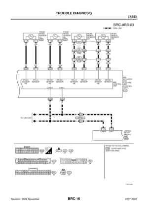 16
16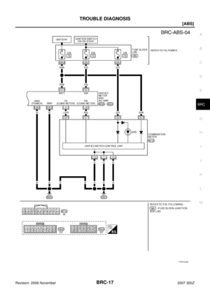 17
17 18
18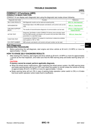 19
19 20
20 21
21 22
22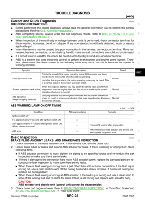 23
23 24
24 25
25 26
26 27
27 28
28 29
29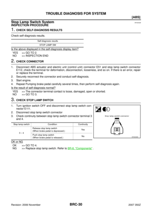 30
30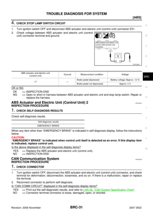 31
31 32
32 33
33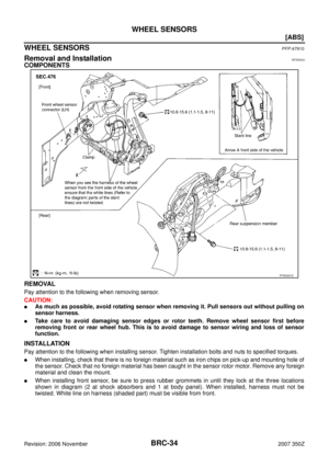 34
34 35
35 36
36 37
37 38
38 39
39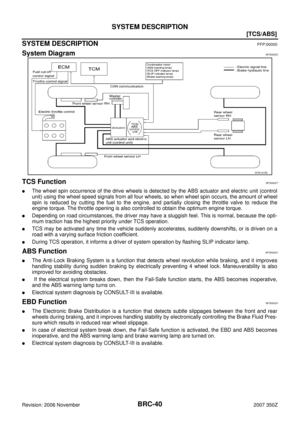 40
40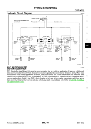 41
41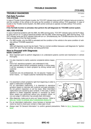 42
42 43
43 44
44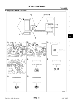 45
45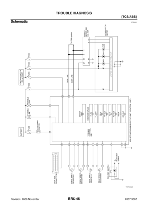 46
46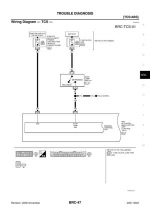 47
47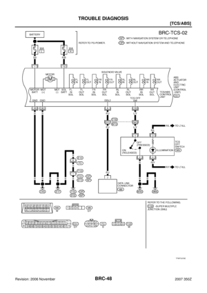 48
48 49
49 50
50 51
51 52
52 53
53 54
54 55
55 56
56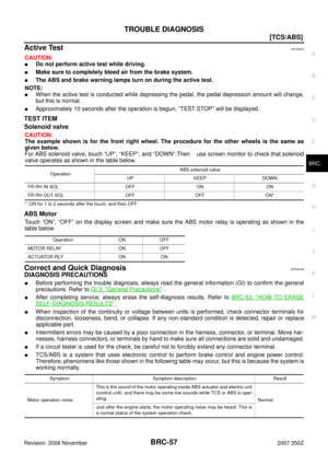 57
57 58
58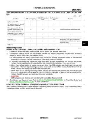 59
59 60
60 61
61 62
62 63
63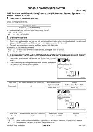 64
64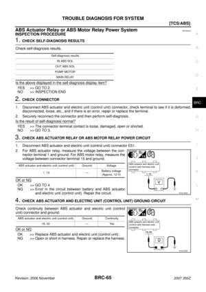 65
65 66
66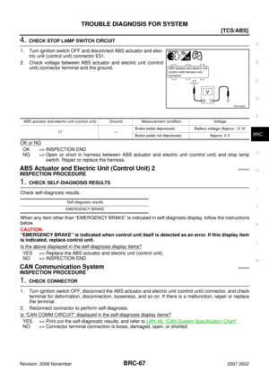 67
67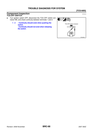 68
68 69
69 70
70 71
71 72
72 73
73 74
74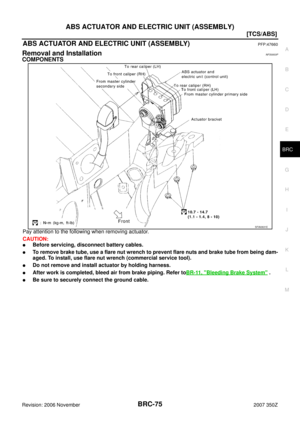 75
75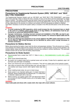 76
76 77
77 78
78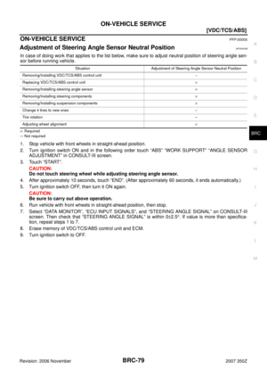 79
79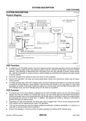 80
80 81
81 82
82 83
83 84
84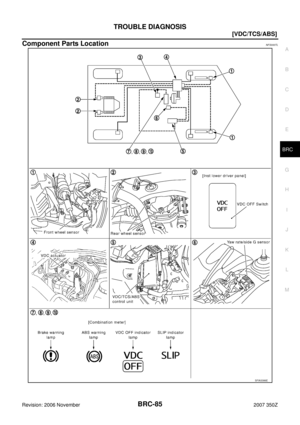 85
85 86
86 87
87 88
88 89
89 90
90 91
91 92
92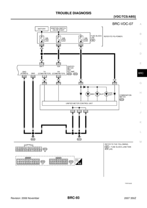 93
93 94
94 95
95 96
96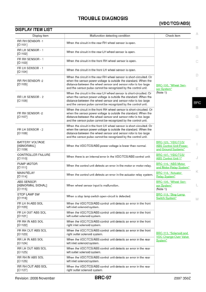 97
97 98
98 99
99 100
100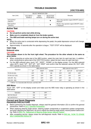 101
101 102
102 103
103 104
104 105
105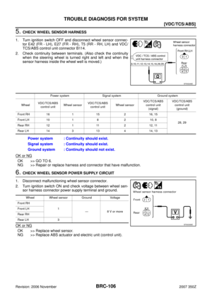 106
106 107
107 108
108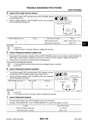 109
109 110
110 111
111 112
112 113
113 114
114 115
115 116
116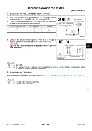 117
117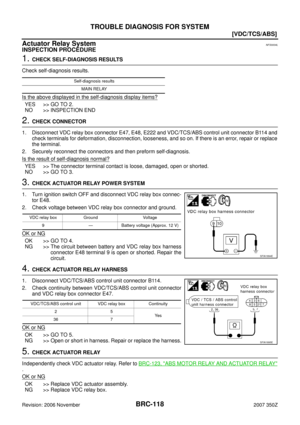 118
118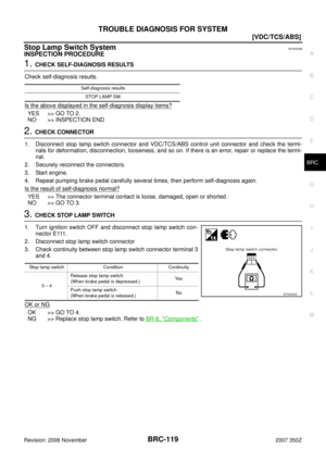 119
119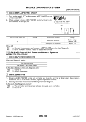 120
120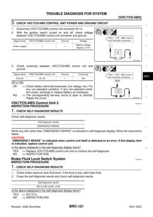 121
121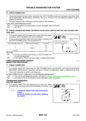 122
122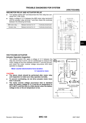 123
123 124
124 125
125 126
126 127
127 128
128 129
129 130
130 131
131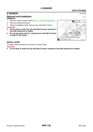 132
132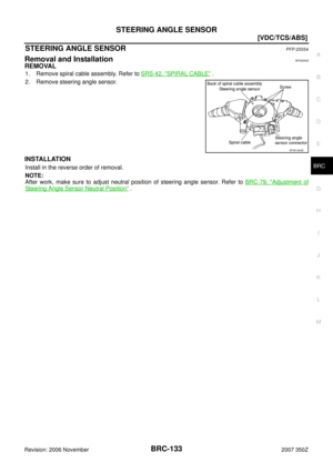 133
133![NISSAN 350Z 2007 Z33 Brake Control System Workshop Manual TROUBLE DIAGNOSIS
BRC-17
[ABS]
C
D
E
G
H
I
J
K
L
MA
B
BRC
Revision: 2006 November2007 350Z
TFWT0046E](/manual-img/5/758/w960_758-16.png "NISSAN 350Z 2007 Z33 Brake Control System Workshop Manual TROUBLE DIAGNOSIS
BRC-17
[ABS]
C
D
E
G
H
I
J
K
L
MA
B
BRC
Revision: 2006 November2007 350Z
TFWT0046E")
![NISSAN 350Z 2007 Z33 Brake Control System Workshop Manual BRC-24
[ABS]
TROUBLE DIAGNOSIS
Revision: 2006 November2007 350Z
POWER SYSTEM TERMINAL LOOSENESS AND BATTERY INSPECTION
Make sure the battery positive cable, negative cable and ground connection are no](/manual-img/5/758/w960_758-23.png "NISSAN 350Z 2007 Z33 Brake Control System Workshop Manual BRC-24
[ABS]
TROUBLE DIAGNOSIS
Revision: 2006 November2007 350Z
POWER SYSTEM TERMINAL LOOSENESS AND BATTERY INSPECTION
Make sure the battery positive cable, negative cable and ground connection are no")