2007 NISSAN 350Z Brake Control System Workshop Manual
-
 1
1 -
 2
2 -
 3
3 -
 4
4 -
 5
5 -
 6
6 -
 7
7 -
 8
8 -
 9
9 -
 10
10 -
 11
11 -
 12
12 -
 13
13 -
 14
14 -
 15
15 -
 16
16 -
 17
17 -
 18
18 -
 19
19 -
 20
20 -
 21
21 -
 22
22 -
 23
23 -
 24
24 -
 25
25 -
 26
26 -
 27
27 -
 28
28 -
 29
29 -
 30
30 -
 31
31 -
 32
32 -
 33
33 -
 34
34 -
 35
35 -
 36
36 -
 37
37 -
 38
38 -
 39
39 -
 40
40 -
 41
41 -
 42
42 -
 43
43 -
 44
44 -
 45
45 -
 46
46 -
 47
47 -
 48
48 -
 49
49 -
 50
50 -
 51
51 -
 52
52 -
 53
53 -
 54
54 -
 55
55 -
 56
56 -
 57
57 -
 58
58 -
 59
59 -
 60
60 -
 61
61 -
 62
62 -
 63
63 -
 64
64 -
 65
65 -
 66
66 -
 67
67 -
 68
68 -
 69
69 -
 70
70 -
 71
71 -
 72
72 -
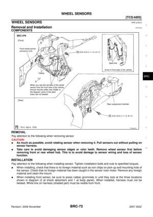 73
73 -
 74
74 -
 75
75 -
 76
76 -
 77
77 -
 78
78 -
 79
79 -
 80
80 -
 81
81 -
 82
82 -
 83
83 -
 84
84 -
 85
85 -
 86
86 -
 87
87 -
 88
88 -
 89
89 -
 90
90 -
 91
91 -
 92
92 -
 93
93 -
 94
94 -
 95
95 -
 96
96 -
 97
97 -
 98
98 -
 99
99 -
 100
100 -
 101
101 -
 102
102 -
 103
103 -
 104
104 -
 105
105 -
 106
106 -
 107
107 -
 108
108 -
 109
109 -
 110
110 -
 111
111 -
 112
112 -
 113
113 -
 114
114 -
 115
115 -
 116
116 -
 117
117 -
 118
118 -
 119
119 -
 120
120 -
 121
121 -
 122
122 -
 123
123 -
 124
124 -
 125
125 -
 126
126 -
 127
127 -
 128
128 -
 129
129 -
 130
130 -
 131
131 -
 132
132 -
 133
133
![NISSAN 350Z 2007 Z33 Brake Control System Workshop Manual VDC/TCS/ABS CONTROL UNIT
BRC-129
[VDC/TCS/ABS]
C
D
E
G
H
I
J
K
L
MA
B
BRC
Revision: 2006 November2007 350Z
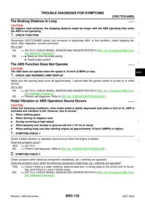
VDC/TCS/ABS CONTROL UNITPFP:47660
Removal and InstallationNFS0004Z
REMOVAL
1. Remove dash sid](/manual-img/5/758/w960_758-128.png "NISSAN 350Z 2007 Z33 Brake Control System Workshop Manual VDC/TCS/ABS CONTROL UNIT
BRC-129
[VDC/TCS/ABS]
C
D
E
G
H
I
J
K
L
MA
B
BRC
Revision: 2006 November2007 350Z
VDC/TCS/ABS CONTROL UNITPFP:47660
Removal and InstallationNFS0004Z
REMOVAL
1. Remove dash sid")
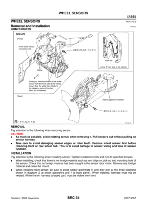
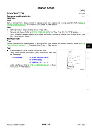
![NISSAN 350Z 2007 Z33 Brake Control System Workshop Manual BRC-130
[VDC/TCS/ABS]
SENSOR ROTOR
Revision: 2006 November2007 350Z
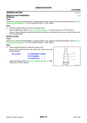
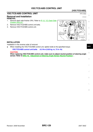
SENSOR ROTORPFP:47970
Removal and InstallationNFS00050
REMOVAL
Front
Sensor rotor cannot be disassembled. To replace sensor rotor, r](/manual-img/5/758/w960_758-129.png "NISSAN 350Z 2007 Z33 Brake Control System Workshop Manual BRC-130
[VDC/TCS/ABS]
SENSOR ROTOR
Revision: 2006 November2007 350Z
SENSOR ROTORPFP:47970
Removal and InstallationNFS00050
REMOVAL
Front
Sensor rotor cannot be disassembled. To replace sensor rotor, r")
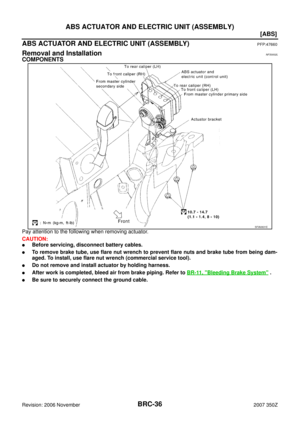
![NISSAN 350Z 2007 Z33 Brake Control System Workshop Manual VDC/TCS/ABS ACTUATOR
BRC-131
[VDC/TCS/ABS]
C
D
E
G
H
I
J
K
L
MA
B
BRC
Revision: 2006 November2007 350Z
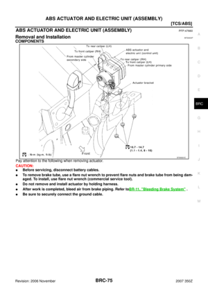
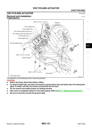
VDC/TCS/ABS ACTUATORPFP:47660
Removal and InstallationNFS00051
COMPONENTS
Pay attention to the fo](/manual-img/5/758/w960_758-130.png "NISSAN 350Z 2007 Z33 Brake Control System Workshop Manual VDC/TCS/ABS ACTUATOR
BRC-131
[VDC/TCS/ABS]
C
D
E
G
H
I
J
K
L
MA
B
BRC
Revision: 2006 November2007 350Z
VDC/TCS/ABS ACTUATORPFP:47660
Removal and InstallationNFS00051
COMPONENTS
Pay attention to the fo")
![NISSAN 350Z 2007 Z33 Brake Control System Workshop Manual BRC-132
[VDC/TCS/ABS]
G SENSOR
Revision: 2006 November2007 350Z
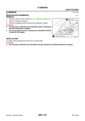
G SENSORPFP:47930
Removal and InstallationNFS00052
REMOVAL
1. Remove center console. Refer to IP-16, "CENTER CONSOLE" .
2. Remove harnes](/manual-img/5/758/w960_758-131.png "NISSAN 350Z 2007 Z33 Brake Control System Workshop Manual BRC-132
[VDC/TCS/ABS]
G SENSOR
Revision: 2006 November2007 350Z
G SENSORPFP:47930
Removal and InstallationNFS00052
REMOVAL
1. Remove center console. Refer to IP-16, \"CENTER CONSOLE\" .
2. Remove harnes")
![NISSAN 350Z 2007 Z33 Brake Control System Workshop Manual STEERING ANGLE SENSOR
BRC-133
[VDC/TCS/ABS]
C
D
E
G
H
I
J
K
L
MA
B
BRC
Revision: 2006 November2007 350Z
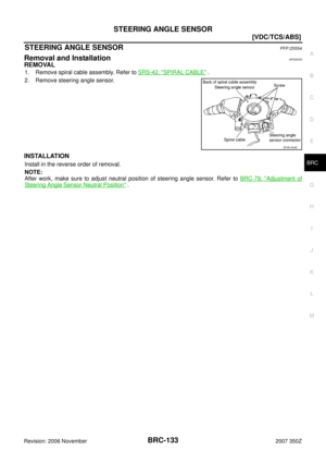
STEERING ANGLE SENSORPFP:25554
Removal and InstallationNFS00053
REMOVAL
1. Remove spiral cable a](/manual-img/5/758/w960_758-132.png "NISSAN 350Z 2007 Z33 Brake Control System Workshop Manual STEERING ANGLE SENSOR
BRC-133
[VDC/TCS/ABS]
C
D
E
G
H
I
J
K
L
MA
B
BRC
Revision: 2006 November2007 350Z
STEERING ANGLE SENSORPFP:25554
Removal and InstallationNFS00053
REMOVAL
1. Remove spiral cable a")
![NISSAN 350Z 2007 Z33 Brake Control System Workshop Manual BRC-134
[VDC/TCS/ABS]
STEERING ANGLE SENSOR
Revision: 2006 November2007 350Z](/manual-img/5/758/w960_758-133.png "NISSAN 350Z 2007 Z33 Brake Control System Workshop Manual BRC-134
[VDC/TCS/ABS]
STEERING ANGLE SENSOR
Revision: 2006 November2007 350Z")