2007 MITSUBISHI LANCER EVOLUTION belt
[x] Cancel search: beltPage 593 of 1449

MPI -Troubleshooting13A-61
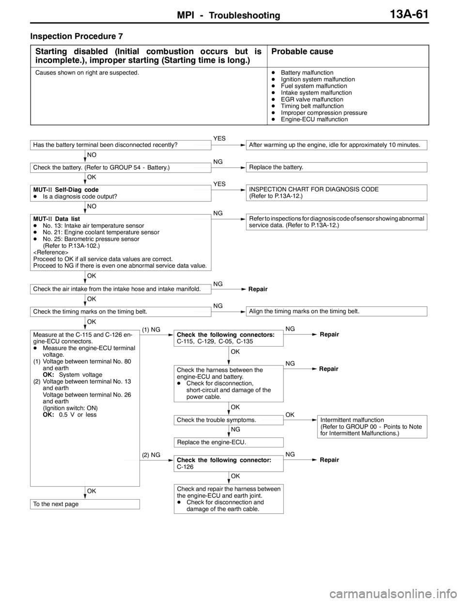
Inspection Procedure 7
Starting disabled (Initial combustion occurs but is
incomplete.), improper starting (Starting time is long.)
Probable cause
Causes shown on right are suspected.DBattery malfunction
DIgnition system malfunction
DFuel system malfunction
DIntake system malfunction
DEGR valve malfunction
DTiming belt malfunction
DImproper compression pressure
DEngine-ECU malfunction
OK
To the next page
OK
Check and repair the harness between
the engine-ECU and earth joint.
DCheck for disconnection and
damage of the earth cable.
(2) NGCheck the following connector:
C-126NG
Repair
NG
Replace the engine-ECU.
OK
Check the trouble symptoms.OKIntermittent malfunction
(Refer to GROUP 00 - Points to Note
for Intermittent Malfunctions.) NG
OK
Check the harness between the
engine-ECU and battery.
DCheck for disconnection,
short-circuit and damage of the
power cable.Repair
OK
Measure at the C-115 and C-126 en-
gine-ECU connectors.
DMeasure the engine-ECU terminal
voltage.
(1) Voltage between terminal No. 80
and earth
OK:System voltage
(2) Voltage between terminal No. 13
and earth
Voltage between terminal No. 26
and earth
(Ignition switch: ON)
OK:0.5 V or less(1) NGCheck the following connectors:
C-115, C-129, C-05, C-135NG
Repair
OK
Check the timing marks on the timing belt.NGAlign the timing marks on the timing belt.
OK
Check the air intake from the intake hose and intake manifold.NG
Repair
NO
MUT-IIData list
DNo. 13: Intake air temperature sensor
DNo. 21: Engine coolant temperature sensor
DNo. 25: Barometric pressure sensor
(Refer to P.13A-102.)
Proceed to OK if all service data values are correct.
Proceed to NG if there is even one abnormal service data value.NGRefer to inspections for diagnosis code of sensor showing abnormal
service data. (Refer to P.13A-12.)
OK
MUT-IISelf-Diag code
DIs a diagnosis code output?YESINSPECTION CHART FOR DIAGNOSIS CODE
(Refer to P.13A-12.)
NO
Check the battery. (Refer to GROUP 54 - Battery.)NGReplace the battery.
Has the battery terminal been disconnected recently?YESAfter warming up the engine, idle for approximately 10 minutes.
Page 595 of 1449

MPI -Troubleshooting13A-63
Inspection Procedure 8
Unstable idling (Rough idling, hunting), inappropriate
idling speed (High or low idling speed), engine stalls (Die
out) during idling
Probable cause
Causes shown on right are suspected.DIdle speed control system malfunction
DAir/fuel ratio control system malfunction
DIgnition system malfunction
DFuel system malfunction
DIntake and exhaust system malfunction
DExhaust gas purifier system malfunction
DThrottle valve malfunction
DTiming belt malfunction
DImproper compression pressure
DEngine-ECU malfunction
OK
To the next page
OK
MUT-IIData list
DNo. 11: Oxygen sensor (front) (Refer to P.13A-102.)NGCheck the Code No. P0130: Oxygen sensor (front) system.
(Refer to P.13A-24.)
OK
Check the throttle body (throttle valve section) for contamination.NGClean the throttle body (throttle valve section).
(Refer to P.13A-126.)
OK
Check the air intake from the intake hose and intake manifold.NG
Repair
OK
Check the timing marks on the timing belt.NGAlign the timing marks on the timing belt.
OK
MUT-IIData list
DNo. 27: Power steering fluid pressure switch
(Refer to P.13A-103.)NGCheck the Power steering fluid pressure switch system. (Refer to
P.13A-51, PROCEDURE FOR DAIGNOSIS CODE P0551)
OK
MUT-IIData list
DNo. 45: Idle speed control servo position (Refer to P.13A-105.)NGCheck the Idle speed control servo (stepper motor) system. (Refer
to P.13A - 49 PROCEDURE FOR DIAGNOSIS CODE P0505)
NO
MUT-IIData list
DNo. 12: Air flow sensor
DNo. 13: Intake air temperature sensor
DNo. 14: Throttle position sensor
DNo. 21: Engine coolant temperature sensor
DNo. 25: Barometric pressure sensor
(Refer to P.13A-102.)
Proceed to OK if all service data values are correct.
Proceed to NG if there is even one abnormal service data value.NGRefer to inspections for diagnosis code of sensor showing abnormal
service data. (Refer to P.13A-12.)
NO
MUT-IISelf-Diag code
DIs a diagnosis code output?YESINSPECTION CHART FOR DIAGNOSIS CODE
(Refer to P.13A-12.)
Has the battery terminal been disconnected recently?YESAfter warming up the engine, idle for approximately 10 minutes.
Page 600 of 1449

MPI -Troubleshooting13A-68
Inspection Procedure 11
Pulsation (Hesitation, sag), poor acceleration, stumbling,
surging
Probable cause
Causes shown on right are suspected.DAir/fuel ratio control system malfunction
DIgnition system malfunction
DFuel system malfunction
DIntake and exhaust system malfunction
DExhaust gas purifier system malfunction
DImproper compression pressure
DTurbocharger system malfunction
OK
To the next page
OK
MUT-IIData list
DNo. 59: Oxygen sensor (rear) (Refer to P.13A-105.)
(Refer to P.13A-27.)
OK
MUT-IIData list
DNo. 11: Oxygen sensor (front) (Refer to P.13A-102.)NGCheck the Code No. P0130: Oxygen sensor (front) system.
(Refer to P.13A-24.)
OK
Check the EGR valve for sticking.
(Refer to GROUP 17 - Exhaust Gas Purifier Check.)NGReplace the EGR valve.
OK
Check the EGR control solenoid valve.
(Refer to GROUP 17 - Exhaust Gas Purifier Check.)NGReplace the EGR control solenoid valve.
OK
Check the purge control solenoid valve.
(Refer to GROUP 17 - Exhaust Gas Purifier Check.)NGReplace the purge control solenoid valve.
OK
MUT-IIData list
DNo. 13: Intake air temperature sensor
DNo. 14: Throttle position sensor
DNo. 21: Engine coolant temperature sensor
DNo. 25: Barometric pressure sensor
(Refer to P.13A-102.)
Proceed to OK if all service data values are correct.
Proceed to NG if there is even one abnormal service data value.NGRefer to inspections for diagnosis code of sensor showing
abnormal service data. (Refer to P.13A-12.)
OK
Check the injector operation sound. (Use sound scope.)NGCheck the Code No. P0201 - 204: Injector system for faulty
cylinder.
NO
Check the ignition timing.
(Refer to GROUP 11 - Engine Adjustment.)NGCheck mounting state of crank angle sensor and timing belt cover.
MUT-IISelf-Diag code
DIs a diagnosis code output?YESINSPECTION CHART FOR DIAGNOSIS CODE
(Refer to P.13A-12.)
Page 605 of 1449

MPI -Troubleshooting13A-73
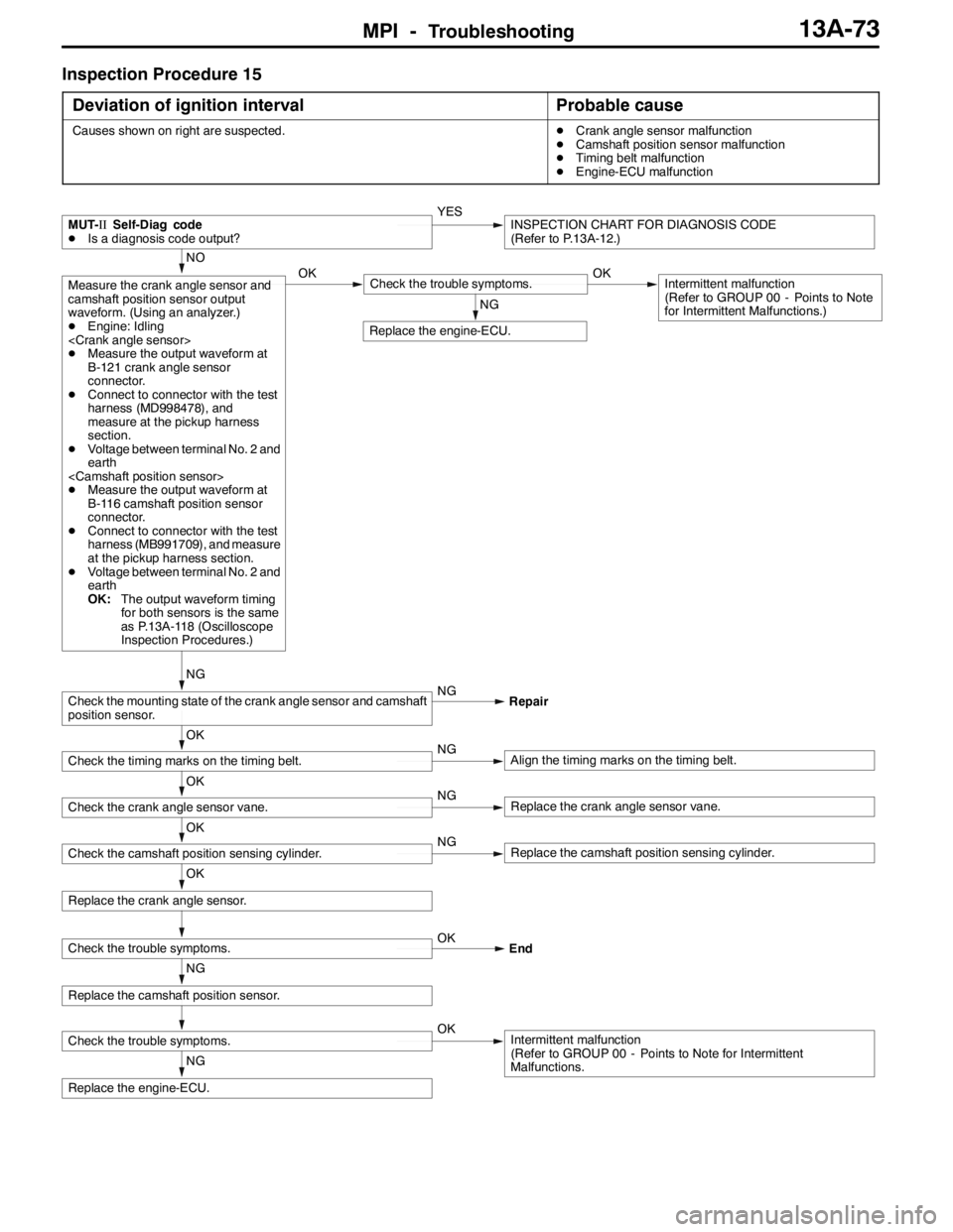
Inspection Procedure 15
Deviation of ignition interval
Probable cause
Causes shown on right are suspected.DCrank angle sensor malfunction
DCamshaft position sensor malfunction
DTiming belt malfunction
DEngine-ECU malfunction
NG
Replace the engine-ECU.
Check the trouble symptoms.OKIntermittent malfunction
(Refer to GROUP 00 - Points to Note for Intermittent
Malfunctions.
NG
Replace the camshaft position sensor.
Check the trouble symptoms.OK
End
OK
Replace the crank angle sensor.
NG
Replace the engine-ECU.
OK
Check the camshaft position sensing cylinder.NGReplace the camshaft position sensing cylinder.
OK
Check the crank angle sensor vane.NGReplace the crank angle sensor vane.
OK
Check the timing marks on the timing belt.NGAlign the timing marks on the timing belt.
NG
Check the mounting state of the crank angle sensor and camshaft
position sensor.NG
Repair
NO
Measure the crank angle sensor and
camshaft position sensor output
waveform. (Using an analyzer.)
DEngine: Idling
DMeasure the output waveform at
B-121 crank angle sensor
connector.
DConnect to connector with the test
harness (MD998478), and
measure at the pickup harness
section.
DVoltage between terminal No. 2 and
earth
DMeasure the output waveform at
B-116 camshaft position sensor
connector.
DConnect to connector with the test
harness (MB991709), and measure
at the pickup harness section.
DVoltage between terminal No. 2 and
earth
OK:The output waveform timing
for both sensors is the same
as P.13A-118 (Oscilloscope
Inspection Procedures.)OKCheck the trouble symptoms.OKIntermittent malfunction
(Refer to GROUP 00 - Points to Note
for Intermittent Malfunctions.)
MUT-IISelf-Diag code
DIs a diagnosis code output?YESINSPECTION CHART FOR DIAGNOSIS CODE
(Refer to P.13A-12.)
Page 651 of 1449

MPI -Troubleshooting13A-119
DExample 2
Cause of problem
Loose timing belt
Abnormality in sensor disk
Wave pattern characteristics
Wave pattern is displaced to the left or right.
INJECTOR
Measurement Method
1. Disconnect the injector connector, and then connect the
special tool (test harness: MB991348) in between.
(All terminals should be connected.)
2. Connect the analyzer special patterns pickup to terminal
No. 2 of the injector connector.
Alternate Method (Test harness not available)
1. Connect the analyzer special patterns pickup to
engine-ECU terminal No. 1. (When checking the No. 1
cylinder.)
2. Connect the analyzer special patterns pickup to
engine-ECU terminal No. 14. (When checking the No.
2 cylinder.)
3. Connect the analyzer special patterns pickup to
engine-ECU terminal No. 2. (When checking the No. 3
cylinder.)
4. Connect the analyzer special patterns pickup to
engine-ECU terminal No. 15. (When checking the No.
4 cylinder.)
Standard Wave Pattern
Observation conditions
FunctionSpecial patterns
Pattern heightVariable
Variable knobAdjust while viewing the wave pattern
Pattern selectorDisplay
Engine r/minIdle speed
Special
patterns
pickupAnalyzer
Page 690 of 1449

ENGINE COOLING -GeneralInformation/
Service Specifications/Lubricant/Sealant14-2
GENERAL INFORMATION
The cooling system is designed to keep every part
of the engine at appropriate temperature in
whatever condition the engine may be operated.
The cooling method is of the water-cooled, pressure
forced circulation type in which the water pump
pressurizes coolant and circulates it throughout the
engine. If the coolant temperature exceeds the
prescribed temperature, the thermostat opens to
circulate the coolant through the radiator as well
so that the heat absorbed by the coolant may be
radiated into the air.The water pump is of the centrifugal type and is
driven by the drive belt from the crankshaft.
The radiator is the corrugated fin, down flow type.
The cooling fan is controlled by the radiator fan
controller and engine-ECU depend on driving
conditions.
ItemSpecification
Radiator performance kJ/h216,700
SERVICE SPECIFICATIONS
ItemsStandard valueLimit
Radiator cap opening pressure kPa93 - 12383
Range of coolant antifreeze concentration of radiator %30 - 60-
ThermostatValve opening temperature of thermostat_C80±1.5-
Full-opening temperature of thermostat_C93-
Valve lift (at 93_C) mm9.5 or more-
LUBRICANT
ItemSpecified coolantQuantity L
Engine coolantMITSUBISHI GENUINE COOLANT or equivalent6.0Enginecoolant
(including reserve tank)
MITSUBISHIGENUINECOOLANTorequivalent6.0
SEALANT
ItemSpecified sealantRemark
Cylinder block drain plug3M Nut Locking Part No. 4171 or equivalentDrying sealant
Page 701 of 1449

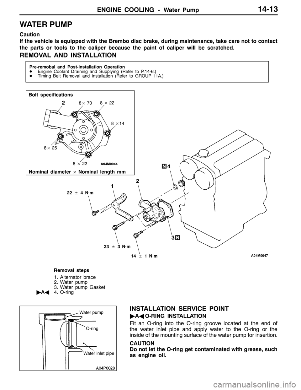
ENGINE COOLING -Water Pump14-13
WATER PUMP
Caution
If the vehicle is equipped with the Brembo disc brake, during maintenance, take care not to contact
the parts or tools to the caliper because the paint of caliper will be scratched.
REMOVAL AND INSTALLATION
Pre-remobal and Post-installation Operation
DEngine Coolant Draining and Supplying (Refer to P.14-6.)
DTiming Belt Removal and installation (Refer to GROUP 11A.)
1
Bolt specifications
28×22
2
23±3 N·m
14±1 N·m
Nominal diameter×Nominal length mm
8×70
8×14
8×22 8×25
3 4
22±4 N·m
Removal steps
1. Alternator brace
2. Water pump
3. Water pump Gasket
"AA4. O-ring
INSTALLATION SERVICE POINT
"AAO-RING INSTALLATION
Fit an O-ring into the O-ring groove located at the end of
the water inlet pipe and apply water to the O-ring or the
inside of the mounting surface of the water pump for insertion.
CAUTION
Do not let the O-ring get contaminated with grease, such
as engine oil.Water pump
O-ring
Water inlet pipe
Page 736 of 1449

ENGINE ELECTRICAL -Charging System16-4
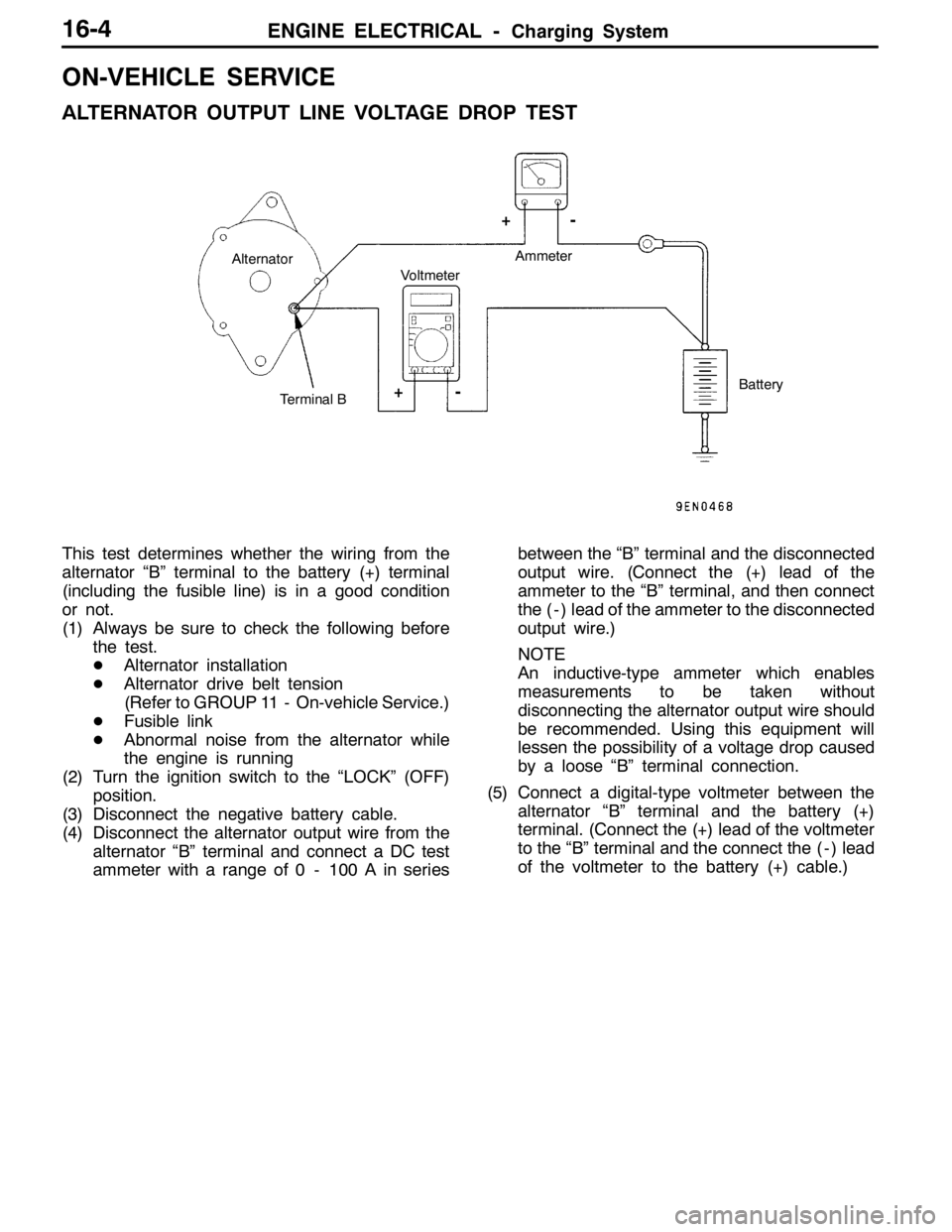
ON-VEHICLE SERVICE
ALTERNATOR OUTPUT LINE VOLTAGE DROP TEST
Alternator
Terminal BVoltmeterAmmeter
Battery
+-
+-
This test determines whether the wiring from the
alternator “B” terminal to the battery (+) terminal
(including the fusible line) is in a good condition
or not.
(1) Always be sure to check the following before
the test.
DAlternator installation
DAlternator drive belt tension
(Refer to GROUP 11 - On-vehicle Service.)
DFusible link
DAbnormal noise from the alternator while
the engine is running
(2) Turn the ignition switch to the “LOCK” (OFF)
position.
(3) Disconnect the negative battery cable.
(4) Disconnect the alternator output wire from the
alternator “B” terminal and connect a DC test
ammeter with a range of 0 - 100 A in seriesbetween the “B” terminal and the disconnected
output wire. (Connect the (+) lead of the
ammeter to the “B” terminal, and then connect
the ( - ) lead of the ammeter to the disconnected
output wire.)
NOTE
An inductive-type ammeter which enables
measurements to be taken without
disconnecting the alternator output wire should
be recommended. Using this equipment will
lessen the possibility of a voltage drop caused
by a loose “B” terminal connection.
(5) Connect a digital-type voltmeter between the
alternator “B” terminal and the battery (+)
terminal. (Connect the (+) lead of the voltmeter
to the “B” terminal and the connect the ( - ) lead
of the voltmeter to the battery (+) cable.)