Page 479 of 1449
ENGINE OVERHAUL -Timing Belt11B-25
(4) Measure the depression amount when the rod is
pressed with a force of 98 to 196 N. If not at the
standard value, replace the auto tensioner.
Standard value: 1 mm or less
Depression
amount 98 - 196 N
Page 489 of 1449

ENGINE OVERHAUL -Rocker Arm and Camshaft11B-35
REMOVAL SERVICE POINT
AA"LASH ADJUSTER REMOVAL
Caution
When reusing the lash adjuster, always clean and inspect
it before installing. (Refer to the section on checking the
lash adjuster.)
INSTALLATION SERVICE POINTS
"AALASH ADJUSTER INSTALLATION
Caution
When reusing the lash adjuster, always clean and inspect
it before installing. (Refer to the section on checking the
lash adjuster.)
Assembly the lash adjuster onto the rocker arm while taking
care not to spill out diesel oil in it.
"BACAMSHAFT INSTALLATION
1. Apply engine oil on the camshaft journal and cam.
2. Install the camshaft onto the cylinder head.
Caution
Do not mistake the intake and exhaust camshafts.
There is a 4 mm width slit on the back end of the
exhaust side camshaft.
"CABEARING CAP INSTALLATION
1. Set the camshaft’s dowel pin to the approximate top.
2. The bearing caps No. 2 to 5 have the same shape. Check
the identification symbol before installing to prevent
mistaking the cap No., intake side and exhaust side.
Identification symbol
(Stamped on front and on No. 2 to 5 bearing caps)
I : Intake side
E : Exhaust side
Timing belt side
Slit
Exhaust side
Dowel pins
Cap No.
Identification
of IN side and
EX side
Page 497 of 1449

ENGINE OVERHAUL -Cylinder Head and Valve11B-43
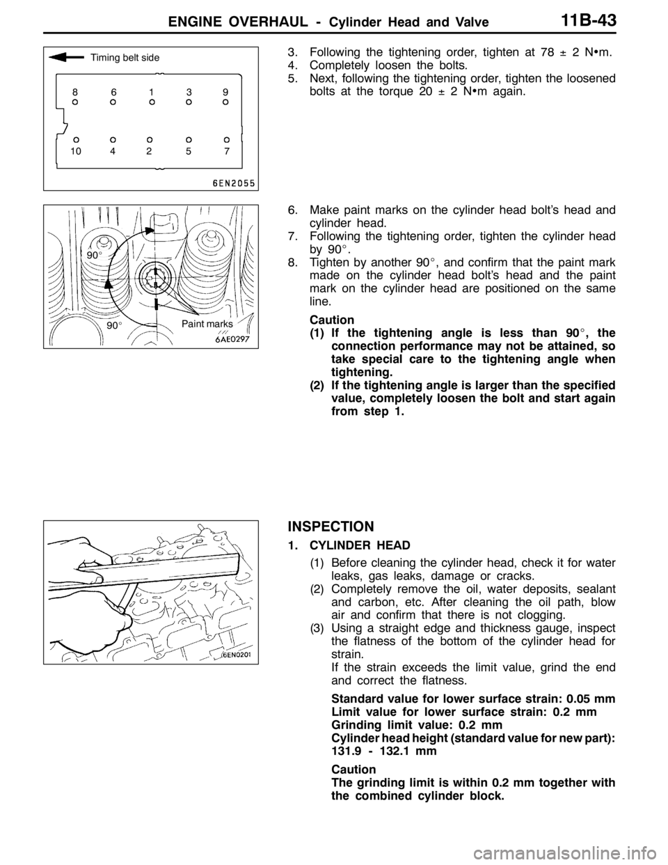
3. Following the tightening order, tighten at 78±2N•m.
4. Completely loosen the bolts.
5. Next, following the tightening order, tighten the loosened
bolts at the torque 20±2N•m again.
6. Make paint marks on the cylinder head bolt’s head and
cylinder head.
7. Following the tightening order, tighten the cylinder head
by 90_.
8. Tighten by another 90_, and confirm that the paint mark
made on the cylinder head bolt’s head and the paint
mark on the cylinder head are positioned on the same
line.
Caution
(1) If the tightening angle is less than 90_, the
connection performance may not be attained, so
take special care to the tightening angle when
tightening.
(2) If the tightening angle is larger than the specified
value, completely loosen the bolt and start again
from step 1.
INSPECTION
1. CYLINDER HEAD
(1) Before cleaning the cylinder head, check it for water
leaks, gas leaks, damage or cracks.
(2) Completely remove the oil, water deposits, sealant
and carbon, etc. After cleaning the oil path, blow
air and confirm that there is not clogging.
(3) Using a straight edge and thickness gauge, inspect
the flatness of the bottom of the cylinder head for
strain.
If the strain exceeds the limit value, grind the end
and correct the flatness.
Standard value for lower surface strain: 0.05 mm
Limit value for lower surface strain: 0.2 mm
Grinding limit value: 0.2 mm
Cylinder head height (standard value for new part):
131.9 - 132.1 mm
Caution
The grinding limit is within 0.2 mm together with
the combined cylinder block.
Timing belt side
86139
10 4 2 5 7
90_
90_
Paint marks
Page 507 of 1449

ENGINE OVERHAUL -Oil Pump and Oil Pan11B-53
"JAPLUG CAP INSTALLATION
1. Install a new O-ring onto the oil pump case.
2. Lightly tighten the plug cap by hand.
3. As shown in the illustration, fit the special tool (MD998162)
into the notch on the plug cap, and while supporting with
the special tool (MD998783), tighten the plug cap at the
specified torque 23±3N•m.
"KAOIL PRESSURE SWITCH INSTALLATION
Sealant
Specified sealant:
3M
TMAAD Part No. 8672 or equivalent
Caution
(1) Make sure that the sealant does not protrude to the
end of the threads.
(2) Do not tighten too far.
"LAOIL PAN INSTALLATION
1. Clean the surface of the cylinder block and oil pan onto
which gasket is to be applied.
2. Squeeze out form-in-place gasket at a 4 mm width, and
apply onto the entire periphery of the oil pan flange.
Form-in-place gasket
Specified gasket:
Mitsubishi Genuine Part No. MD970389 or
equivalent
3. Note that the lengths of the bolts shown in the illustration
differ, so take care when installing.
MD998162
MD998783
Bolt hole section Groove
Timing belt side
M6×8
Page 519 of 1449

ENGINE OVERHAUL -Crankshaft and Cylinder Block11B-65
INSTALLATION SERVICE POINTS
"AATHRUST BEARING INSTALLATION
1. Install the thrust bearing onto the cylinder block side of
the No. 3 bearing section. The bearing can be installed
easily by applying engine oil.
2. Install the thrust bearing so that the side with the groove
faces the crankshaft weight side.
"BACRANKSHAFT BEARING INSTALLATION
1. Measure the diameter of the crankshaft journal, and
confirm the class shown below. When using a spare part,
each identification colour is painted at the position shown
in the illustration.
2. The cylinder block bearing section bore identification mark
is stamped at the position shown in the illustration.
Crankshaft journalCylinder
block
bearing
Spare
bearing
identificaClassProduct
identifica-
tion colourSpare part
identifica-
tion colourJournal
diameter
mmbearing
section
bore iden-
tification
markidentifica-
tion mark
1NoneYellow56.994 -57 0000057.00011
22
2NoneNone56.988 -56 9940156.99412
23
3NoneWhite56.982 -56 9880256.98813
24
Groove
No. 2
No. 1No. 4
No. 5No. 3
Timing belt side
Cylinder block bearing section
bore identification mark
No. 1No. 2No. 3No. 4
No. 5
Cylinder
bore size
mark
Page 520 of 1449
![MITSUBISHI LANCER EVOLUTION 2007 Service Repair Manual ENGINE OVERHAUL -Crankshaft and Cylinder Block11B-66
3. Select the bearing from the above table according to
the identification confirmed in steps 1 and 2.
[Example of selecting bearing]
(1) If the me MITSUBISHI LANCER EVOLUTION 2007 Service Repair Manual ENGINE OVERHAUL -Crankshaft and Cylinder Block11B-66
3. Select the bearing from the above table according to
the identification confirmed in steps 1 and 2.
[Example of selecting bearing]
(1) If the me](/manual-img/19/57084/w960_57084-519.png)
ENGINE OVERHAUL -Crankshaft and Cylinder Block11B-66
3. Select the bearing from the above table according to
the identification confirmed in steps 1 and 2.
[Example of selecting bearing]
(1) If the measured outer diameter of the crankshaft
journal is 57.000 mm, Class 1 applies, and the
identification colour is yellow.
(2) If the cylinder block bearing bore identification mark
is 0, select identification mark 0 in consideration of
step (1).
4. Install the grooved bearing on the cylinder block side.
5. Install the bearing with no oil groove onto the beam bearing
cap side.
"CABEAM BEARING CAP/BEARING CAP BOLT
INSTALLATION
1. Install the beam bearing cap with the arrow facing the
timing belt side.
2. Before installing the bearing cap bolt, confirm that the
bolt’s underhead length is less than the limit value.
Replace the bolt if it exceeds the limit value.
Limit value: 71.1 mm
3. Apply engine oil on the bolt threads and bolt surface.
4. Following the tightening order, tighten the bearing cap
bolt at 25±2N•m.
5. Make paint marks on the bolt head.
6. Using the position of the mark painted on the bolt head
as reference, make paint marks on the seat surface at
the 90_to 100_positions in the tightening direction.
7. Following the tightening order, tighten the bolt by 90_
to 100_, and confirm that the paint marks made on the
bolt and seat surface match.
Caution
(1) If the tightening angle is less than 90_, the
connection performance may not be attained, so
take special care when tightening.
(2) If the tightening angle exceeds 100_, completely
loosen the nut, and start again from step 1.Crankshaft bearing side
identification mark position
Identification
mark
Groove
Upper bearing
Lower bearing
Underhead length
Arrow
84159
732610
Paint marksPaint marks
90°- 100°
Page 526 of 1449

ENGINE LUBRICATION -General Information12-2
GENERAL INFORMATION
The lubrication method is a fully force-fed, full-flow
filtration type. The oil pump is a gear type which
is driven by the crankshaft via the timing belt.
ENGINE OILS
Health Warning
Prolonged and repeated contact with mineral oil
will result in the removal of natural fats from the
skin, leading to dryness, irritation and dermatitis.
In addition, used engine oil contains potentiallyharmful contaminants which may cause skin cancer.
Adequate means of skin protection and washing
facilities must be provided.
Recommended Precautions
The most effective precaution is to adapt working
practices which prevent, as far as practicable, the
risk of skin contact with mineral oils, for example
by using enclosed systems for handling used engine
oil and by degreasing components, where
practicable, before handling them.
Other precautions:
DAvoid prolonged and repeated contact with oils,
particularly used engine oils.
DWear protective clothing, including impervious
gloves where practicable.
DAvoid contaminating clothes, particularly
underpants, with oil.
DDo not put oily rags in pockets, the use of
overalls without pockets will avoid this.
DDo not wear heavily soiled clothing and
oil - impregnated foot - wear. Overalls must be
cleaned regularly and kept separate from
personal clothing.DWhere there is a risk of eye contact, eye
protection should be worn, for example,
chemical goggles or face shields; in addition
an eye wash facility should be provided.
DObtain First Aid treatment immediately for open
cuts and wounds.
DWash regularly with soap and water to ensure
all oil is removed, especially before meals (skin
cleansers and nail brushes will help). After
cleaning, the application of preparations
containing lanolin to replace the natural skin
oils is advised.
DDo not use petrol, kerosine, diesel fuel, gas
oil, thinners or solvents for cleaning skin.
DUse barrier creams, applying them before each
work period, to help the removal of oil from
the skin after work.
DIf skin disorders develop, obtain medical advice
without delay.
Page 591 of 1449

MPI -Troubleshooting13A-59
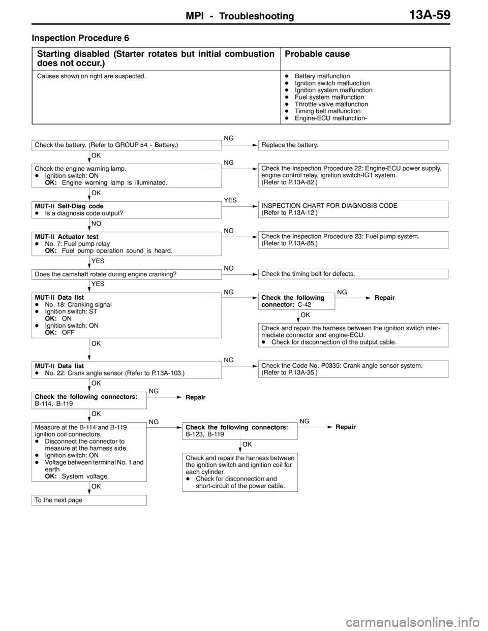
Inspection Procedure 6
Starting disabled (Starter rotates but initial combustion
does not occur.)
Probable cause
Causes shown on right are suspected.DBattery malfunction
DIgnition switch malfunction
DIgnition system malfunction
DFuel system malfunction
DThrottle valve malfunction
DTiming belt malfunction
DEngine-ECU malfunction-
OK
To the next page
OK
Check and repair the harness between
the ignition switch and ignition coil for
each cylinder.
DCheck for disconnection and
short-circuit of the power cable.
OK
Measure at the B-114 and B-119
ignition coil connectors.
DDisconnect the connector to
measure at the harness side.
DIgnition switch: ON
DVoltage between terminal No. 1 and
earth
OK:System voltageNGCheck the following connectors:
B-123, B-119NG
Repair
OK
Check the following connectors:
B-114, B-119NG
Repair
OK
MUT-IIData list
DNo. 22: Crank angle sensor (Refer to P.13A-103.)NGCheck the Code No. P0335: Crank angle sensor system.
(Refer to P.13A-35.)
OK
Check and repair the harness between the ignition switch inter-
mediate connector and engine-ECU.
DCheck for disconnection of the output cable.
YES
MUT-IIData list
DNo. 18: Cranking signal
DIgnition switch: ST
OK:ON
DIgnition switch: ON
OK:OFFNGCheck the following
connector:C-42NG
Repair
YES
Does the camshaft rotate during engine cranking?NOCheck the timing belt for defects.
NO
MUT-IIActuator test
DNo. 7: Fuel pump relay
OK:Fuel pump operation sound is heard.NOCheck the Inspection Procedure 23: Fuel pump system.
(Refer to P.13A-85.)
OK
MUT-IISelf-Diag code
DIs a diagnosis code output?YESINSPECTION CHART FOR DIAGNOSIS CODE
(Refer to P.13A-12.)
OK
Check the engine warning lamp.
DIgnition switch: ON
OK:Engine warning lamp is illuminated.NGCheck the Inspection Procedure 22: Engine-ECU power supply,
engine control relay, ignition switch-IG1 system.
(Refer to P.13A-82.)
Check the battery. (Refer to GROUP 54 - Battery.)NGReplace the battery.