Page 455 of 1449
11B-1
ENGINE
OVERHAUL
CONTENTS
GENERAL DESCRIPTION 2...................
SPECIFICATIONS 3..........................
Service Specifications 3.........................
Machining Standards 5.........................
Tightening Torque 5............................
Sealants 8.....................................
Form-In-Place Gasket 8........................
SPECIAL TOOLS 9...........................
ALTERNATOR AND IGNITION SYSTEM 12....
TIMING BELT 13.............................
FUEL SYSTEM 26............................SECONDARY AIR SYSTEM AND INTAKE
MANIFOLD 28...............................
EXHAUST MANIFOLD 30.....................
WATER PUMP AND WATER HOSE 32........
ROCKER ARMS AND CAMSHAFT 34.........
CYLINDER HEAD AND VALVE 40.............
OIL PUMP AND OIL PAN 47.................
PISTON AND CONNECTING ROD 56..........
CRANKSHAFT AND CYLINDER BLOCK 64....
Page 457 of 1449

ENGINE OVERHAUL -Specifications11B-3
SPECIFICATIONS
SERVICE SPECIFICATIONS
Unit: mm
Items
Standard valueLimited value
Timing belt
Timing belt B
Vibration frequency Hz (during inspection)
Vibration frequency Hz (when re-tensing working belt)
Vibration frequency Hz (when mounting new belt)
Deflection amount (during inspection)
Deflection amount (when re-tensing working belt)
Deflection amount (when mounting new belt)
Auto-tensioner
Rod protrusion length (free length)
Rod protrusion length (when mounting timing belt)
Rod recess amount (when pressed at 98 to 196 N•m)
56 - 92
76 - 92
76 - 92
5-10
5-7
5-7
12.0
3.8 - 4.5
Within 1
-
-
-
Rocker arm, camshaft
Camshaft
Cam height
Intake
Exhaust
35.79
35.4935.29
34.99
Cylinder head, valve
Cylinder head
Lower surface strain
Lower surface grinding limit (in combination with combined cylinder block)
Total height
Valve
Margin
Intake
Exhaust
Total length
Intake
Exhaust
Valve spring
Free height
Squareness
Valve guide
Clearance between valve guide and valve stem
Intake
Exhaust
Total length
Intake
Exhaust
Protrusion amount
Valve seat
Contact width
Valve protrusion amount from spring seat surface
Intake
Exhaust
0.05
-
131.9 - 132.1
1.0
1.5
109.50
109.70
48.3
1.5_or less
0.02 - 0.05
0.05 - 0.09
45.5
50.5
19.2 - 19.8
0.9 - 1.3
49.20
48.400.2
0.2
-
0.5
1.0
109.00
109.20
47.3
4_
0.10
0.15
-
-
-
-
49.70
48.90
Page 459 of 1449

ENGINE OVERHAUL -Specifications11B-5
MACHINING STANDARDS
Unit: mm
Items
Standard valueLimited value
Cylinder head, valve
Cylinder head
Oversize valve guide hole diameter
0.05 O.S.
0.25 O.S.
0.50 O.S.
Oversize valve seat hole diameter
Intake
0.3 O.S.
0.6 O.S.
Exhaust
0.3 O.S.
0.6 O.S.
12.05 - 12.07
12.25 - 12.27
12.50 - 12.52
35.30 - 35.33
35.60 - 35.63
33.30 - 33.33
33.60 - 33.63-
-
-
-
-
-
-
TIGHTENING TORQUE
ItemsTightening torque N·m
Alternator, ignition system
Oil level gauge guide bolt13±1
Water pump pulley bolt8.8±1.0
Alternator brace bolt (flange)23±3
Alternator brace bolt (washer)22±4
Alternator nut44±10
Crankshaft pulley bolt25±4
Center cover bolt3±0.5
Ignition coil bolt10±2
Spark plug25±5
Connector bracket bolt8.8±1.0
Timing belt
Timing belt cover bolt (flange)11±1
Timing belt cover bolt (washer)9±1
Power steering pump bracket bolt49±9
Tensioner pulley bolt49±6
Tensioner arm bolt21±4
Auto tensioner bolt23±3
Idler pulley bolt35±6
Crank angle sensor bolt8.8±1.0
Oil pump sprocket nut54±5
Crankshaft bolt162±5
Tensioner B bolt19±3
Counter balance shaft sprocket bolt46±3
Rocker cover bolt3.5±0.5
Engine support bracket bolt49±5
Page 463 of 1449
ENGINE OVERHAUL -Special Tools11B-9
SPECIAL TOOLS
ToolNumberNameUse
MD998781Flywheel stopperFixing of flywheel
MD998778Crankshaft
sprocketRemoval of crankshaft sprocket and
crankshaft sprocket B
MB998785Sprocket stopperHolding of counter balance shaft sprocket
MB991704Battery harnessMeasurement of timing belt B tension
(Use together with MUT-II.)
MB991502MUT-IIsub
assemblyMeasurement of timing belt B tension
(Use together with MB991704 and
MB991668.)
MB991668Belt tension meter
setMeasurement of timing belt B tension
(Use together with MUT-II.)
MD998767Tension pulley
socket wrenchOperation of tensioner pulley during adjust-
ment of timing belt tension
MD998738Set screwHolding of tensioner arm and auto tensioner
during installation of timing belt
MD998713Camshaft oil seal
installerInstallation of camshaft oil seal
Page 467 of 1449

ENGINE OVERHAUL -Timing Belt11B-13
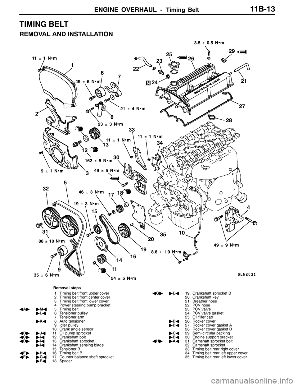
TIMING BELT
REMOVAL AND INSTALLATION
1
11±1N•m
2
3
4 56
7
8
910
11 1213
14 15
16 1718
192021 2223
2425
26
27
2829
30
313233
34
35
49±6N•m
21±4N•m
23±3N•m
11±1N•m11±1N•m
88±10 N•m
35±6N•m
54±5N•m 19±3N•m 46±3N•m 9±1N•m162±5N•m3.5±0.5 N•m
49±9N•m
8.8±1.0 N•m 49±5N•m
Removal steps
1. Timing belt front upper cover
2. Timing belt front center cover
3. Timing belt front lower cover
4. Power steering pump bracket
AA""MA5. Timing belt
"LA6. Tensioner pulley
7. Tensioner arm
"KA8. Auto tensioner
9. Idler pulley
10. Crank angle sensor
AB""JA11. Oil pump sprocket
AC""IA12. Crankshaft bolt
AD""IA13. Crankshaft sprocket
"IA14. Crankshaft sensing blade
15. Tensioner B
AE""HA16. Timing belt B
AF""GA17. Counter balance shaft sprocket
"FA18. SpacerAG""EA19. Crankshaft sprocket B
20. Crankshaft key
21. Breather hose
22. PCV hose
23. PCV valve
24. PCV valve gasket
25. Oil filler cap
"DA26. Rocker cover
"DA27. Rocker cover gasket A
28. Rocker cover gasket B
"CA29. Semi-circular packing
"BA30. Engine support bracket
AH""AA31. Camshaft sprocket bolt
32. Camshaft sprocket
33. Timing belt rear right cover
34. Timing belt rear left upper cover
35. Timing belt rear left lower cover
Page 468 of 1449

ENGINE OVERHAUL -Timing Belt11B-14
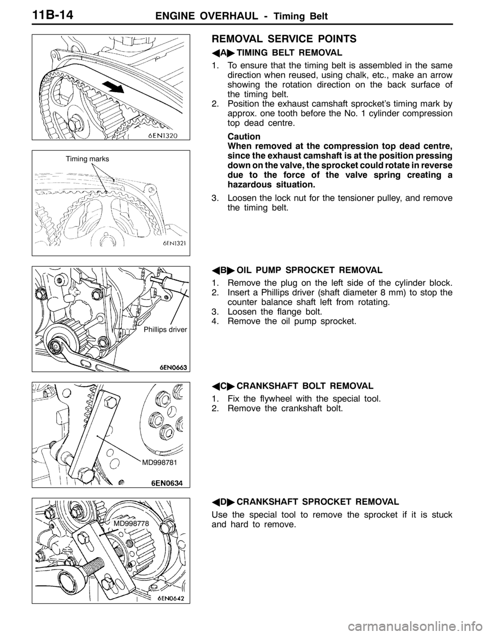
REMOVAL SERVICE POINTS
AA"TIMING BELT REMOVAL
1. To ensure that the timing belt is assembled in the same
direction when reused, using chalk, etc., make an arrow
showing the rotation direction on the back surface of
the timing belt.
2. Position the exhaust camshaft sprocket’s timing mark by
approx. one tooth before the No. 1 cylinder compression
top dead centre.
Caution
When removed at the compression top dead centre,
since the exhaust camshaft is at the position pressing
down on the valve, the sprocket could rotate in reverse
due to the force of the valve spring creating a
hazardous situation.
3. Loosen the lock nut for the tensioner pulley, and remove
the timing belt.
AB"OIL PUMP SPROCKET REMOVAL
1. Remove the plug on the left side of the cylinder block.
2. Insert a Phillips driver (shaft diameter 8 mm) to stop the
counter balance shaft left from rotating.
3. Loosen the flange bolt.
4. Remove the oil pump sprocket.
AC"CRANKSHAFT BOLT REMOVAL
1. Fix the flywheel with the special tool.
2. Remove the crankshaft bolt.
AD"CRANKSHAFT SPROCKET REMOVAL
Use the special tool to remove the sprocket if it is stuck
and hard to remove.
Timing marks
Phillips driver
MD998781
MD998778
Page 469 of 1449
ENGINE OVERHAUL -Timing Belt11B-15
AE"TIMING BELT B REMOVAL
To ensure that the timing belt is assembled in the same
direction when reused, using chalk, etc., make an arrow
showing the rotation direction on the back surface of the
timing belt.
AF"COUNTER BALANCE SHAFT SPROCKET
REMOVAL
1. Fix the counter balance shaft sprocket with the special
tool.
2. Remove the installation bolt of the counter balance shaft.
AG"CRANKSHAFT SPROCKET B REMOVAL
Use the special tool to remove the sprocket if it is stuck
and hard to remove.
AH"CAMSHAFT SPROCKET BOLT REMOVAL
Hold the hexagon part of the camshaft with a wrench, and
remove the camshaft sprocket bolt.
INSTALLATION SERVICE POINTS
"AACAMSHAFT SPROCKET BOLT INSTALLATION
Hold the hexagon part of the camshaft with a wrench, and
tighten the camshaft sprocket bolt at the specified torque
88±10 N•m.
MD998785
MD998778
Page 470 of 1449
ENGINE OVERHAUL -Timing Belt11B-16
"BAENGINE SUPPORT BRACKET INSTALLATION
Before tightening, apply sealant on the bolt at the position
shown in the illustration.
Sealant
Specified sealant:
3M
TMAAD Part No. 8672 or equivalent
"CASEMI-CIRCULAR PACKING INSTALLATION
Apply sealant at the position shown in the illustration.
Sealant
Specified sealant:
3M
TMAAD Part No. 8672 or equivalent
"DAROCKER COVER/ROCKER COVER GASKET A
INSTALLATION
1. Apply form-in-place gasket on the rocker cover at the
position shown in the illustration.
Sealant
Specified sealant:
3M
TMAAD Part No. 8672 or equivalent
2. Install the rocker cover gasket A onto the rocker cover
before the form-in-place gasket hardens.
10 mm
Semi-circular
packing
Cylinder head10 mm
Timing belt side