2007 MITSUBISHI LANCER EVOLUTION air condition
[x] Cancel search: air conditionPage 813 of 1449

MANUAL TRANSMISSION - Troubleshooting
TROUBLESHOOTING
BASIC TROUBLESHOOTING CONDITIONS
Refer to GROUP 00 - How to Use Troubleshooting/Inspection Service Points.
NOTE
Before starting the troubleshooting procedure, make sure that the following items have been checked
okay.
DIs the appropriate steering wheel installed at the center of the steering column shaft correctly?
DAre the tire, wheel size, specifications, air pressure, balance, and wear state normal?
DIs the wheel alignment normal?
DHas the engine, suspension, etc. been remodeled in such a way that it will affect the ACD and AYC
systems?
DIAGNOSIS FUNCTION
READING DIAGNOSIS CODE
Read a diagnosis code by the MUT-IIor ACD mode indicator
lamp. (Refer to GROUP 00 - How to Use Troubleshooting/
Inspection Service Points.)
NOTE
Connect the MUT-IIto the diagnosis connector (16-pin).
ERASING DIAGNOSIS CODES
When using the MUT-II
Connect the MUT-IIto the diagnosis connector (16-pin) and
erase the diagnosis code.
Caution
Turn the ignition switch to the “LOCK”(OFF) position
before connecting or disconnecting the MUT-II.
ACDmode indicator lamp
Page 845 of 1449

MANUAL TRANSMISSION - Troubleshooting
ACTUATOR TEST JUDGEMENT VALUE
Item
no.Check itemTest descriptionNormal state
01Bleeding
according to the steering angle, and operate
the Proportional valve for five minutes.Make sure no air leaks from the bleeder
screw on the transfer.
02Bleeding
according to the steering angle, and operate
the directional valve for five minutes.Make sure no air leaks from the bleeder
screw on the torque transfer differential.
03Check the oil vol-
umeOperate the directional valve to the left and
right for 20 seconds.Check that the oil volume of the reservoir
tank is appropriate.
04Electric pump
driveOperate the electric pump for 5 seconds.Operation sounds of the electric pump
can be heard.
05Check the opera-
tions of the ACDOperate the Proportional valve
supply the maximum oil pressure to the multi
plate clutch.9Generate the tight corner braking
phenomenon.
06Check clutch op-
erations
maximum oil pressure to the left clutch.When the wheels are lifted, speed
difference will occur between the rear
left and right wheels.
07Check clutch op-
erations
maximum oil pressure to the right clutch.When the wheels are lifted, speed
difference will occur between the rear
left and right wheels.
08Control OFFTurn OFF the electric pump relay, and turn
OFF the control of the ACD and AYC.In actual driving, there is difference
between control ON and OFF.
(1) The actuator test can be executed only when all the following conditions are satisfied.
DAll wheel speed sensor inputs below 20 km/h
DNo system malfunction detected
DSteering angle is within±30 degrees from the neutral position
(2) When the actuator test corresponds to one of the following conditions, forced driving will be cleared.
DWhen any one of the wheel speed sensor input is detected to be above 20 km/h (excluding
Item No.08 “Control OFF”.)
DWhen system malfunction is detected (excluding diagnostic code No.82, 84, and 85)
DWhen the forced drive time is exceeded
DWhen the MUT-IIis removed
DWhen the Clear key of the MUT-IIis operated
Page 995 of 1449

REAR AXLE -Differential Carrier
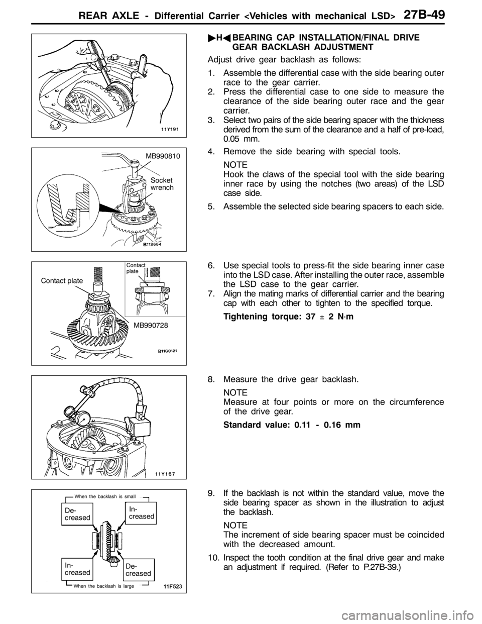
"HABEARING CAP INSTALLATION/FINAL DRIVE
GEAR BACKLASH ADJUSTMENT
Adjust drive gear backlash as follows:
1. Assemble the differential case with the side bearing outer
race to the gear carrier.
2. Press the differential case to one side to measure the
clearance of the side bearing outer race and the gear
carrier.
3. Select two pairs of the side bearing spacer with the thickness
derived from the sum of the clearance and a half of pre-load,
0.05 mm.
4. Remove the side bearing with special tools.
NOTE
Hook the claws of the special tool with the side bearing
inner race by using the notches (two areas) of the LSD
case side.
5. Assemble the selected side bearing spacers to each side.
6. Use special tools to press-fit the side bearing inner case
into the LSD case. After installing the outer race, assemble
the LSD case to the gear carrier.
7. Align the mating marks of differential carrier and the bearing
cap with each other to tighten to the specified torque.
Tightening torque: 37±2N
·m
8. Measure the drive gear backlash.
NOTE
Measure at four points or more on the circumference
of the drive gear.
Standard value: 0.11 - 0.16 mm
9. If the backlash is not within the standard value, move the
side bearing spacer as shown in the illustration to adjust
the backlash.
NOTE
The increment of side bearing spacer must be coincided
with the decreased amount.
10. Inspect the tooth condition at the final drive gear and make
an adjustment if required. (Refer to P.27B-39.)
MB990810
Socket
wrench
Contact plate
MB990728
Contact
plate
De-
creasedIn-
creased
De-
creased In-
creased
When the backlash is large
When the backlash is small
Page 1022 of 1449

POWER PLANT MOUNT - Crossmember32-8
CROSSMEMBER
REMOVAL AND INSTALLATION
Caution
1. Before removing the steering wheel and air bag module assembly, always refer to GROUP
52B - Service Precautions, Air bag Module and Clock Spring. Also, set the front wheels so
that they are facing straight forward, and remove the ignition key. If you fail to do this, the
SRS clock spring will be damaged, causing the SRS air bag to be inoperative and serious
injury.
2. *
1: Indicates parts which should be initially tightened, and then fully tightened after placing
the vehicle horizontally and loading the full weight of the engine on the vehicle body.
3. *
2: Indicates parts which should be temporarily tightened, and then fully tightened with the
vehicle on the ground in the unladen condition.
Caution
If the vehicle is equipped the Brembo disc brake, during maintenance, take care not to contact
the parts or tools to the caliper because the paint of caliper will be scratched.
Pre-removal Operations
DUnder Cover Removal
(Refer to GROUP 51 - Front Bumper.)
DCentermember, Crossmember Bar Removal
(Refer to P.32-6.)
DFront Exhaust Pipe Removal
(Refer to GROUP 15.)
DSteering Wheel Air Bag Module Assembly Removal
(Refer to GROUP 37A.)
DPower Steering Fluid Draining
(Refer to GROUP 37A - On-vehicle Service.)Post-installation Operations
DCentermember, Crossmember Bar Installation
(Refer to P.32-6.)
DFront Exhaust Pipe Installation
(Refer to GROUP 15.)
DSteering Wheel Air Bag Module Assembly
Installation (Refer to GROUP 37A.)
DPower Steering Fluid Supplying
(Refer to GROUP 37A - On-vehicle Service.)
DPower Steering Fluid Line Bleeding
(Refer to GROUP 37A - On-vehicle Service.)
DPress the dust cover with a finger to check whether
the dust cover is cracked or damaged.
DChecking Steering Wheel Position with Wheels
Straight Ahead
DFront Wheel Alignment Check and Adjustment
(Refer to GROUP 37A - On-vehicle Service.)
DUnder Cover Installation
(Refer to GROUP 51 - Front Bumper.)
Page 1038 of 1449

FRONT SUSPENSION -Lower Arm Assembly/Stabilizer Bar33A-12
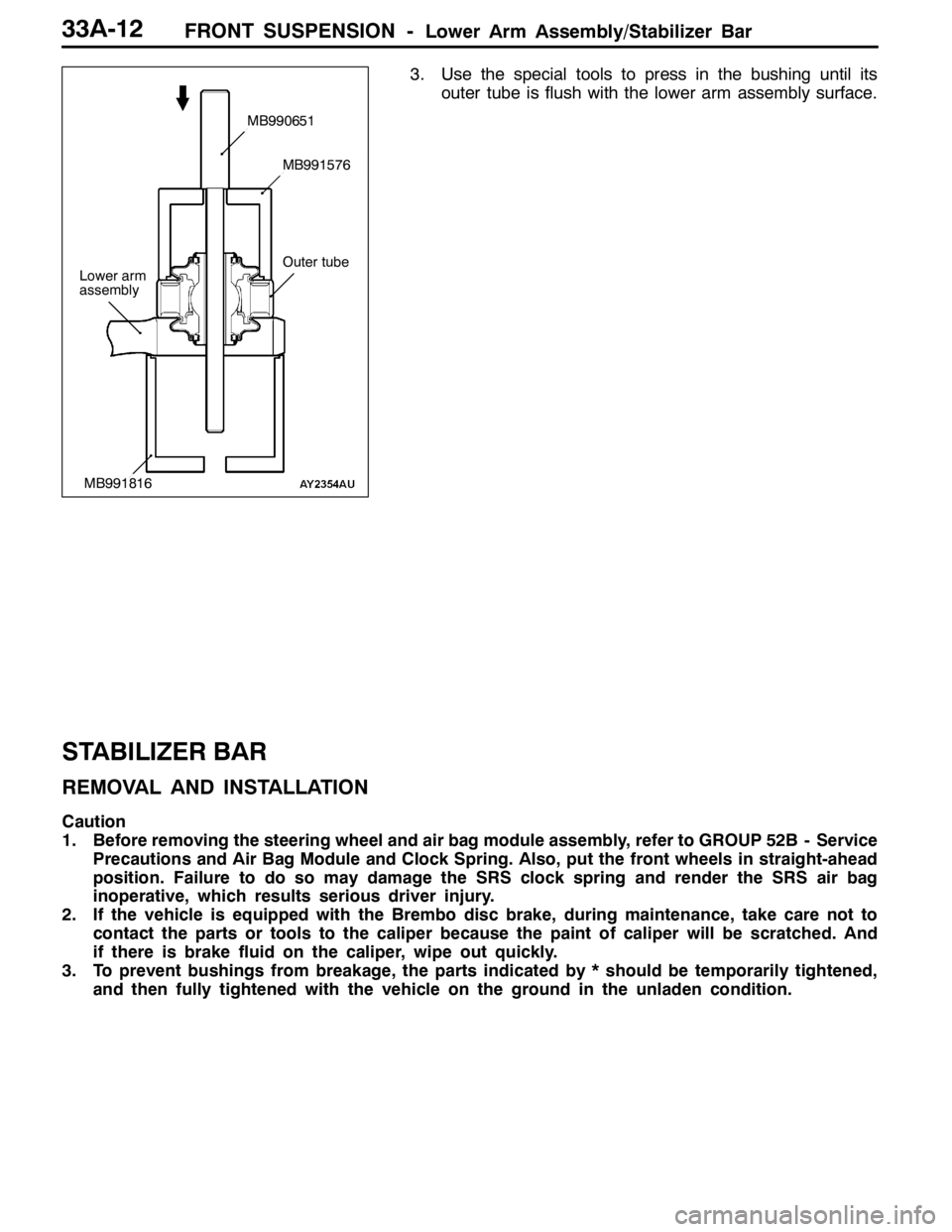
3. Use the special tools to press in the bushing until its
outer tube is flush with the lower arm assembly surface.
STABILIZER BAR
REMOVAL AND INSTALLATION
Caution
1. Before removing the steering wheel and air bag module assembly, refer to GROUP 52B - Service
Precautions and Air Bag Module and Clock Spring. Also, put the front wheels in straight-ahead
position. Failure to do so may damage the SRS clock spring and render the SRS air bag
inoperative, which results serious driver injury.
2. If the vehicle is equipped with the Brembo disc brake, during maintenance, take care not to
contact the parts or tools to the caliper because the paint of caliper will be scratched. And
if there is brake fluid on the caliper, wipe out quickly.
3. To prevent bushings from breakage, the parts indicated by * should be temporarily tightened,
and then fully tightened with the vehicle on the ground in the unladen condition.
Lower arm
assembly
MB990651
MB991576
MB991816
Outer tube
Page 1050 of 1449

BASIC BRAKE SYSTEM -On-vehicle Service35A-8
2. If the brake pedal play is not within the standard value,
check the following, and adjust or replace if necessary:
DExcessive play between the brake pedal and the clevis
pin, or between the clevis pin and the brake booster
operating rod
DBrake pedal height
DInstallation position of the stop lamp switch, etc.
CLEARANCE BETWEEN BRAKE PEDAL AND FLOOR
BOARD
1. Turn up the carpet etc. under the brake pedal.
2. Start the engine, depress the brake pedal with
approximately 500 N of force, and measure the clearance
between the brake pedal and the floorboard.
Standard value (C): 90 mm or more
3. If the clearance is outside the standard value, check for
air trapped in the brake line and thickness of the disc
brake pad and dragging in the parking brake.
Adjust and replace defective parts as required.
4. Return the carpet, etc.
BRAKE BOOSTER OPERATING TEST
For simple checking of the brake booster operation, carry
out the following tests:
1. Run the engine for one or two minutes, and then stop
it.
If the pedal depresses fully the first time but gradually
becomes higher when depressed succeeding times, the
booster is operating properly. If the pedal height remains
unchanged, the booster is defective.
2. With the engine stopped, step on the brake pedal several
times.
Then start the engine while the brake pedal is stepped
on.
If the pedal moves downward slightly, the booster is in
good condition. If there is no change, the booster is
defective.
3. With the engine running, step on the brake pedal and
then stop the engine.
Hold the pedal depressed for 30 seconds. If the pedal
height does not change, the booster is in good condition.
If the pedal rises, the booster is defective.
If the above three tests are okay, the booster performance
can be determined as good.
If one of the above three tests is not okay at least, the check
valve, vacuum hose, or booster will be defective.
C
Good No good
When engine is
stoppedWhen engine is
started
GoodNo good
Page 1055 of 1449

BASIC BRAKE SYSTEM -On-vehicle Service35A-13
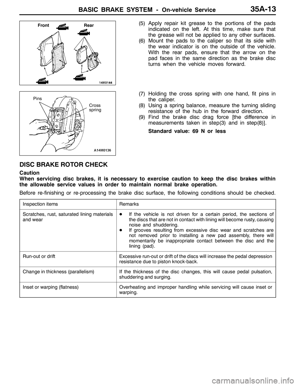
(5) Apply repair kit grease to the portions of the pads
indicated on the left. At this time, make sure that
the grease will not be applied to any other surfaces.
(6) Mount the pads to the caliper so that its side with
the wear indicator is on the outside of the vehicle.
With the rear pads, ensure that the arrow on the
pad faces in the same direction as the brake disc
turns when the vehicle moves forward.
(7) Holding the cross spring with one hand, fit pins in
the caliper.
(8) Using a spring balance, measure the turning sliding
resistance of the hub in the forward direction.
(9) Find the brake disc drag force [the difference in
measurements taken in step(3) and in step(8)].
Standard value: 69 N or less
DISC BRAKE ROTOR CHECK
Caution
When servicing disc brakes, it is necessary to exercise caution to keep the disc brakes within
the allowable service values in order to maintain normal brake operation.
Before re-finishing or re-processing the brake disc surface, the following conditions should be checked.
Inspection itemsRemarks
Scratches, rust, saturated lining materials
and wearDIf the vehicle is not driven for a certain period, the sections of
the discs that are not in contact with lining will become rusty, causing
noise and shuddering.
DIf grooves resulting from excessive disc wear and scratches are
not removed prior to installing a new pad assembly, there will
momentarily be inappropriate contact between the disc and the
lining (pad).
Run-out or driftExcessive run-out or drift of the discs will increase the pedal depression
resistance due to piston knock-back.
Change in thickness (parallelism)If the thickness of the disc changes, this will cause pedal pulsation,
shuddering and surging.
Inset or warping (flatness)Overheating and improper handling while servicing will cause inset or
warping.
Front Rear
Cross
spring
Pins
Page 1089 of 1449

ABS <4WD> -Troubleshooting35B-19
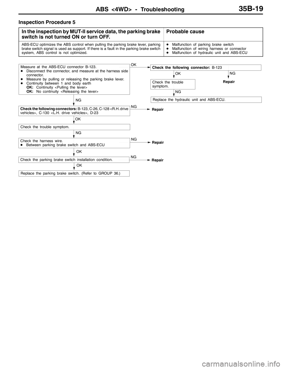
Inspection Procedure 5
In the inspection by MUT-II service data, the parking brake
switch is not turned ON or turn OFF.
Probable cause
ABS-ECU optimizes the ABS control when pulling the parking brake lever, parking
brake switch signal is used as support. If there is a fault in the parking brake switch
system, ABS control is not optimized.DMalfunction of parking brake switch
DMalfunction of wiring harness or connector
DMalfunction of hydraulic unit and ABS-ECU
OK
NG
NG
Check the harness wire.
DBetween parking brake switch and ABS-ECU
Replace the hydraulic unit and ABS-ECU.
OK
NG
OK
Check the trouble symptom.
Repair
NG
RepairCheck the following connectors:B-123, C-26, C-128
Measure at the ABS-ECU connector B-123.
DDisconnect the connector, and measure at the harness side
connector.
DMeasure by pulling or releasing the parking brake lever.
DContinuity between 1 and body earth
OK:Continuity
OK:No continuity
NG
Repair
NG
OK
Check the trouble
symptom.
Check the following connector:B-123
OK
Replace the parking brake switch. (Refer to GROUP 36.)
NG
RepairCheck the parking brake switch installation condition.