2007 MITSUBISHI LANCER EVOLUTION air condition
[x] Cancel search: air conditionPage 1090 of 1449

ABS <4WD> -Troubleshooting35B-20
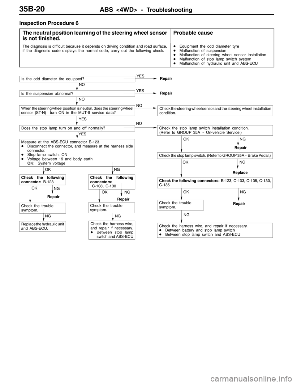
Inspection Procedure 6
The neutral position learning of the steering wheel sensor
is not finished.
Probable cause
The diagnosis is difficult because it depends on driving condition and road surface,
if the diagnosis code displays the normal code, carry out the following check.DEquipment the odd diameter tyre
DMalfunction of suspension
DMalfunction of steering wheel sensor installation
DMalfunction of stop lamp switch system
DMalfunction of hydraulic unit and ABS-ECU
NG
NG
NG
NG
Check the harness wire, and repair if necessary.
DBetween battery and stop lamp switch
DBetween stop lamp switch and ABS-ECU
OK
Check the trouble
symptom.
OK
Check the following connectors:B-123, C-103, C-108, C-130,
C-135
OK
Check the stop lamp switch. (Refer to GROUP 35A - Brake Pedal.)
Check the stop lamp switch installation condition.
(Refer to GROUP 35A - On-vehicle Service.) NO
Repair
OKNG
RepairOKNG
RepairReplace
NG
Replace the hydraulic unit
and ABS-ECU.
NG
Check the harness wire,
and repair if necessary.
DBetween stop lamp
switch and ABS-ECURepair
Check the trouble
symptom.
NG
Check the following
connectors:
C-108, C-130
Check the trouble
symptom.
OK
Check the following
connector:B-123
YES
Measure at the ABS-ECU connector B-123.
DDisconnect the connector, and measure at the harness side
connector.
DStop lamp switch: ON
DVoltage between 19 and body earth
OK:System voltage
Does the stop lamp turn on and off normally?
YES
Repair
NO
Is the odd diameter tire equipped?
YES
Repair
NO
Is the suspension abnormal?
NO
YES
When the steering wheel position is neutral, does the steering wheel
sensor (ST-N) turn ON in the MUT-II service data?Check the steering wheel sensor and the steering wheel installation
condition.
Page 1091 of 1449

ABS <4WD> -Troubleshooting35B-21
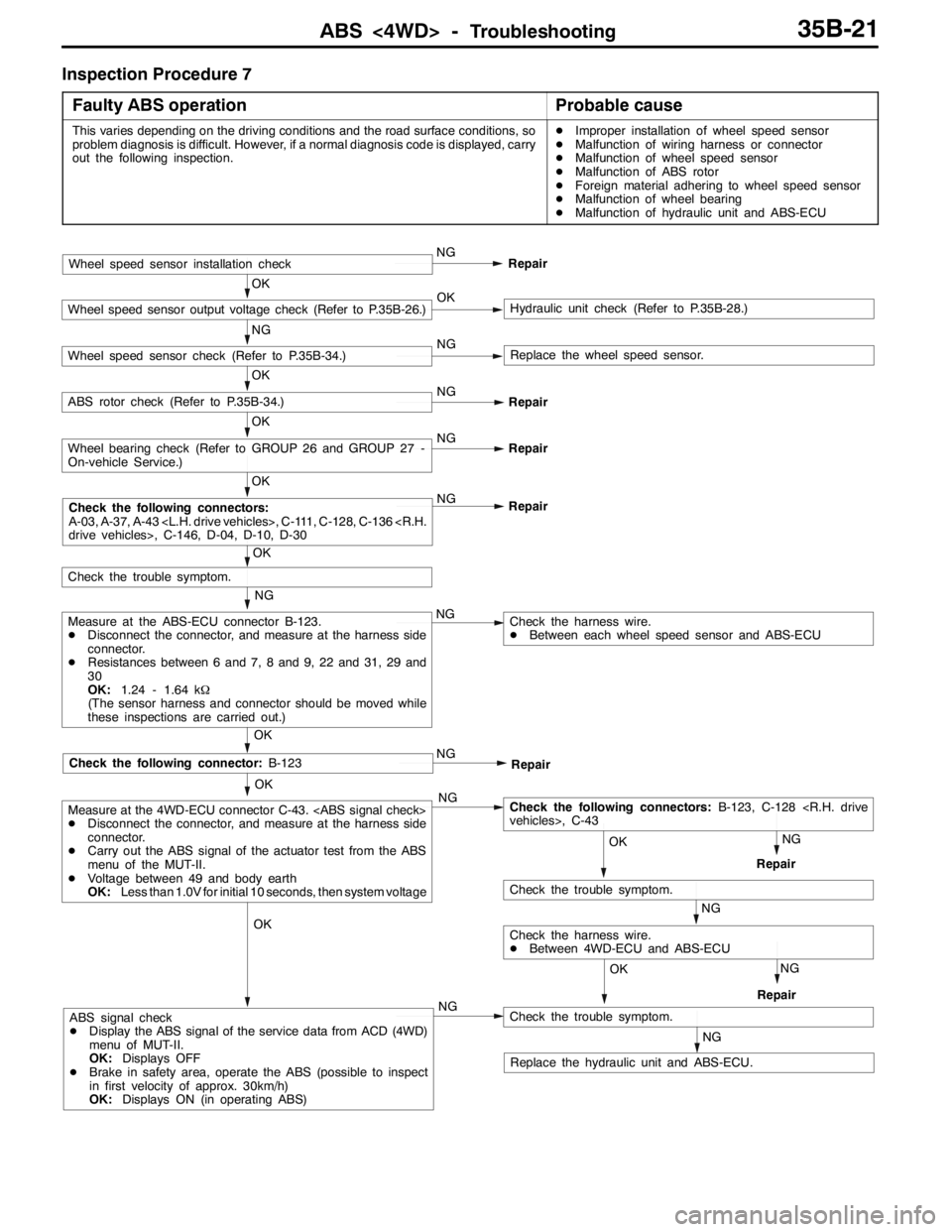
Inspection Procedure 7
Faulty ABS operation
Probable cause
This varies depending on the driving conditions and the road surface conditions, so
problem diagnosis is difficult. However, if a normal diagnosis code is displayed, carry
out the following inspection.DImproper installation of wheel speed sensor
DMalfunction of wiring harness or connector
DMalfunction of wheel speed sensor
DMalfunction of ABS rotor
DForeign material adhering to wheel speed sensor
DMalfunction of wheel bearing
DMalfunction of hydraulic unit and ABS-ECU
OK
OK
Check the following connector:B-123
NG
Measure at the ABS-ECU connector B-123.
DDisconnect the connector, and measure at the harness side
connector.
DResistances between 6 and 7, 8 and 9, 22 and 31, 29 and
30
OK:1.24 - 1.64 kΩ
(The sensor harness and connector should be moved while
these inspections are carried out.)NG
OK
Check the trouble symptom.
OK
NG
Repair
OK
Wheel bearing check (Refer to GROUP 26 and GROUP 27 -
On-vehicle Service.)NG
Repair
OK
ABS rotor check (Refer to P.35B-34.)NG
Repair
NG
Wheel speed sensor check (Refer to P.35B-34.)NGReplace the wheel speed sensor.
OK
Wheel speed sensor output voltage check (Refer to P.35B-26.)OKHydraulic unit check (Refer to P.35B-28.)
Wheel speed sensor installation checkNG
Repair
Check the harness wire.
DBetween each wheel speed sensor and ABS-ECU
NG
Repair
NG
NG
RepairOK
Check the following connectors:B-123, C-128
NG
Check the trouble symptom.
RepairNG
OK
Check the harness wire.
DBetween 4WD-ECU and ABS-ECU OK
Measure at the 4WD-ECU connector C-43.
DDisconnect the connector, and measure at the harness side
connector.
DCarry out the ABS signal of the actuator test from the ABS
menu of the MUT-II.
DVoltage between 49 and body earth
OK:Less than 1.0V for initial 10 seconds, then system voltage
NGABS signal check
DDisplay the ABS signal of the service data from ACD (4WD)
menu of MUT-II.
OK:Displays OFF
DBrake in safety area, operate the ABS (possible to inspect
in first velocity of approx. 30km/h)
OK:Displays ON (in operating ABS)
NG
Check the trouble symptom.
Replace the hydraulic unit and ABS-ECU.
Check the following connectors:
A-03, A-37, A-43
Page 1118 of 1449

STEERING -Service Specifications/Lubricants/Sealant/Special Tools37A-4
SERVICE SPECIFICATIONS
ItemsStandard valueLimit
Steering wheel free play mmwhen engine running-30 or less
with engine stopped0-10-
Steering angleInner wheel31_45’±1_30’-
Outer wheel
Ball joint turning torque N·m1.0 - 3.0-
Stationary steering effort NSteering effort32 or less-
Fluctuation allowance6.0 or less-
Oil pump relief pressure MPa8.4 - 9.0-
Pressure under no-load conditions MPa0.2 - 0.8-
Steering gear retention hydraulic pressure MPa8.4 - 9.0-
Oil pressure switch operating
pressureMPa
OFF→ON1.8 - 2.4-
pressure MPaON→OFF1.0 - 2.4-
Total pinion torque N·mTotal rotation torque0.8 - 1.8-
Torque variation0.49 or less-
Tie rod joint swing resistance N (Tie rod joint swing torque N·m)8 - 27 (1.5 - 4.9)-
Opening dimension of special tool (MB991561) mm2.9-
Band crimped width mm2.4 - 2.8-
LUBRICANTS
ItemsSpecified lubricantQuantity
Power steering fluidAutomatic transmission fluid DEXRONIIApprox. 1.0 L
Tie rod bellowsSilicone greaseAs required
Pinion and valve assemblyRepair kit greaseAs required
Rack assembly
SEALANT
ItemsSpecified sealantRemarks
Toe boad (steering shaft cover
mounting bolt hole)3M ATD Part No. 8513 or equivalentDrying sealant
Rack support cover end plug3M ATD Part No. 8661, 8663 or equivalentSemi-drying sealant
SPECIAL TOOLS
ToolNumberNameUse
MB990635,
MB991113 or
MB991406Steering linkage
pullerDisconnection of tie rod end
Page 1124 of 1449

STEERING -On-vehicle Service37A-10
9. If the level changes more than 5 mm, the air is badly
bled. So, bleed air again.
Caution
(1) If the fluid level rises suddenly after the engine
is stopped, the bleeding is incomplete.
(2) Incomplete bleeding causes abnormal noises
from the pump and the flow-control valve. This
could lessen the life of the pump and the other
parts.
OIL PUMP PRESSURE TEST
1. Disconnect the pressure hose from the oil pump, and
then connect the special tools.
2. Bleed the air, and then turn the steering wheel several
times while the vehicle is not moving so that the
temperature of the fluid rises to approximately 50 - 60_C.
3. Start the engine and idle it at 1,000±100 r/min.
4. Fully close the shut-off valve of the pressure gauge and
measure the oil pump relief pressure to confirm that it
is within the standard value range.
Standard value: 8.4 - 9.0 MPa
5. If the standard value is not met, the oil pump is defective.
So, replace the oil pump. Then, measure oil pressure
again.
6. With the pressure gauge shut - off valve fully open, check
the hydraulic pressure in unladen condition.
Standard value: 0.2 - 0.8 MPa
7. If the standard value is not met, the oil line or steering
gear is probably defective. So, repair and measure oil
pressure again.
8. Turn the steering wheel fully either left or right and check
the retention hydraulic pressure.
Standard value: 8.4 - 9.0 MPa
9. If the pressure is below the standard value, disassemble
and reassemble the steering gear. If above, replace the
oil pump. Then, measure oil pressure again.
10. Remove the special tools, and tighten the pressure hose
to the specified torque.
Tightening torque: 18±3 N·m
11. Bleed the system.
Fluid level change: Within 5 mm
While engine
runningWhile engine
stopped
Temperature
gaugePressure
gauge
(MB990662)Shut-off valve
Oil
pumpOil reservoir
Adapter
(MB990994)
Adapter
(MB990993)
Page 1170 of 1449

BODY -Doors42-22
ADJUSTMENTS AND REPLACEMENT DURING
POWER WINDOW MALFUNCTION
If the window glass does not rise but automatically descends,
adjust and replace the window glass as follows:
1. Remove the door trim and waterproof film. (P.42-27)
2. Remove the window regulator assembly from the door
window glass, and raise and lower the window glass with
your hand and check the operating force.
Remarks Insert a cushion, etc. to prevent damage of
the glass if it accidentally drops.
3. If the door window glass does not rise and descend
smoothly, perform the following check and repair.
DCheck the installation condition of the runchannel.
DStraighten twist in the door sash.
DCheck the installation condition of the lower sash
or the center sash.
NOTE
The lower sash cannot normally be adjusted, but it may
be possible to adjust the sash span slightly within the
range allowed by manufacturing tolerances by pushing
the lower sash outwards while re-installing it.
4. If repair or adjustment is not possible, replace the door
assembly.
POWER WINDOW SAFETY MECHANISM
CHECK
1. Set a wood piece of about 10 mm thick as shown in
the figure, and raise the window glass.
2. Check that the window glass descends by about 150
mm when it catches the wood piece. If it does not, perform
troubleshooting. (Refer to GROUP 54B.)
POWER WINDOW TIMER FUNCTION CHECK
9Close the door and turn the ignition switch in the OFF position,
and then check the power window operates for 30 seconds.
If it does not, perform troubleshooting.(Refer to GROUP 54B.)
Runchannel
Door
sash
Lower sash
Page 1273 of 1449

SRS -Troubleshooting52B-29
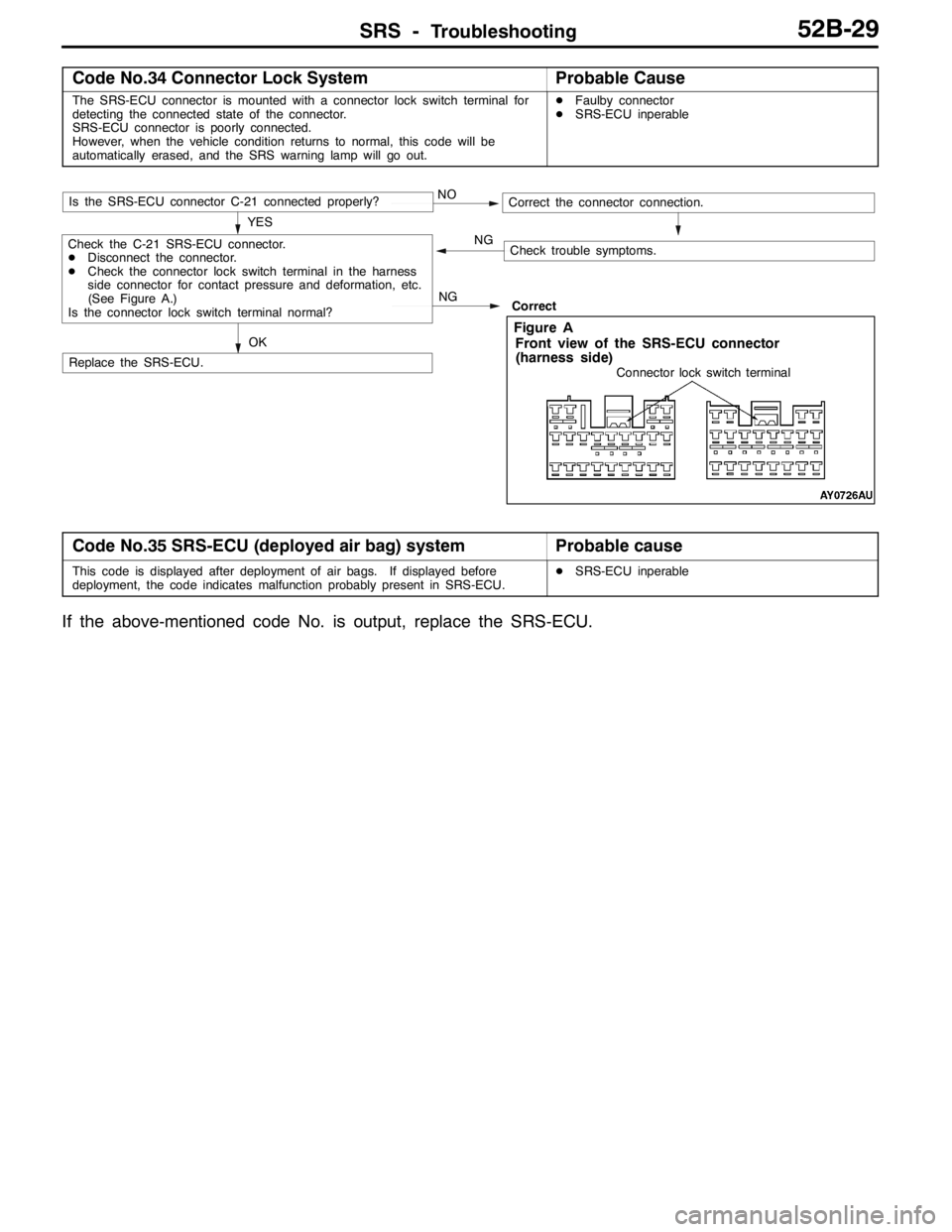
Code No.34 Connector Lock SystemProbable Cause
The SRS-ECU connector is mounted with a connector lock switch terminal for
detecting the connected state of the connector.
SRS-ECU connector is poorly connected.
However, when the vehicle condition returns to normal, this code will be
automatically erased, and the SRS warning lamp will go out.DFaulby connector
DSRS-ECU inperable
NOIs the SRS-ECU connector C-21 connected properly?
Replace the SRS-ECU.Correct YES
OK
Correct the connector connection.
Check trouble symptoms. NG
NGCheck the C-21 SRS-ECU connector.
DDisconnect the connector.
DCheck the connector lock switch terminal in the harness
side connector for contact pressure and deformation, etc.
(See Figure A.)
Is the connector lock switch terminal normal?
Connector lock switch terminal
Front view of the SRS-ECU connector
(harness side)
Figure A
Code No.35 SRS-ECU (deployed air bag) systemProbable cause
This code is displayed after deployment of air bags. If displayed before
deployment, the code indicates malfunction probably present in SRS-ECU.DSRS-ECU inperable
If the above-mentioned code No. is output, replace the SRS-ECU.
Page 1330 of 1449

CHASSIS ELECTRICAL -Ignition Switch and Immobilizer System54A-10
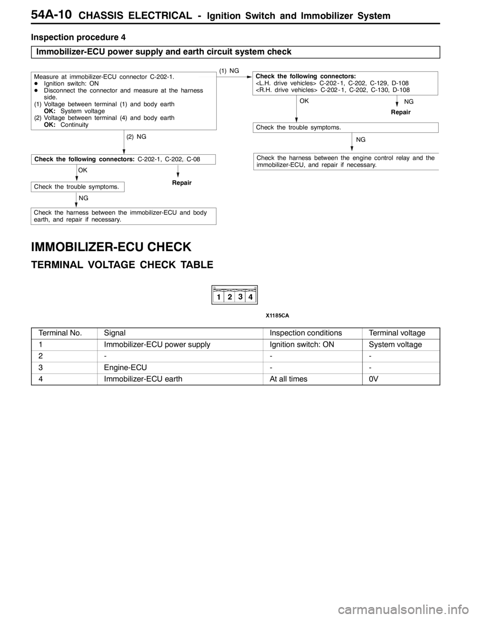
Inspection procedure 4
Immobilizer-ECU power supply and earth circuit system check
NG
Check the harness between the engine control relay and the
immobilizer-ECU, and repair if necessary.
OK
Check the trouble symptoms.
(2) NG
Repair
Measure at immobilizer-ECU connector C-202-1.
DIgnition switch: ON
DDisconnect the connector and measure at the harness
side.
(1) Voltage between terminal (1) and body earth
OK:System voltage
(2) Voltage between terminal (4) and body earth
OK:Continuity(1) NGCheck the following connectors:
NG
NG
OK
Check the trouble symptoms.Repair
NG
Check the following connectors:C-202-1, C-202, C-08
Check the harness between the immobilizer-ECU and body
earth, and repair if necessary.
IMMOBILIZER-ECU CHECK
TERMINAL VOLTAGE CHECK TABLE
Terminal No.SignalInspection conditionsTerminal voltage
1Immobilizer-ECU power supplyIgnition switch: ONSystem voltage
2---
3Engine-ECU--
4Immobilizer-ECU earthAt all times0V
Page 1403 of 1449

55-1
HEATER, AIR
CONDITIONER AND
VENTILATION
CONTENTS
SERVICE SPECIFICATIONS 2.................
LUBRICANTS 2..............................
SPECIAL TOOLS 2...........................
TROUBLESHOOTING 3.......................
ON-VEHICLE SERVICE 14....................
Refrigerant Level Test through Performance Test 14.
Magnetic Clutch Test 14.........................
Receiver Drier Test 14..........................
Compressor Drive Belt Adjustment 15.............
Dual Pressure Switch Check 15..................
Charging 16...................................
Correcting Low Refrigerant Level in case the Service
can used 18...................................
Discharging System 19..........................
Refilling of Oil in the A/C System 19...............
Performance Test 20............................
Refrigerant Leak Repair 21......................
Blower Relay Continuity Check 22................
A/C Compressor Relay Continuity Check 22........Condenser Fan Relay (LO) Check 23.............
Condenser Fan Relay (HI) Check 23..............
Idle-up Operation Check 24.....................
HEATER CONTROL ASSEMBLY (A/C-ECU)
AND A/C SWITCH 25........................
HEATER UNIT AND BLOWER ASSEMBLY 28.
REGISTOR, BLOWER MOTOR AND
INSIDE/OUTSIDE AIR CHANGE OVER
DAMPER MOTOR 32.........................
EVAPORATOR AND AIR THERMO SENSOR
34 ...........................................
COMPRESSOR 36............................
CONDENSER ASSEMBLY AND CONDENSER
FAN ASSEMBLY 40...........................
REFRIGERANT LINES 42.....................
DUCTS 44...................................
VENTILATION 45.............................