2007 MITSUBISHI LANCER EVOLUTION air condition
[x] Cancel search: air conditionPage 567 of 1449
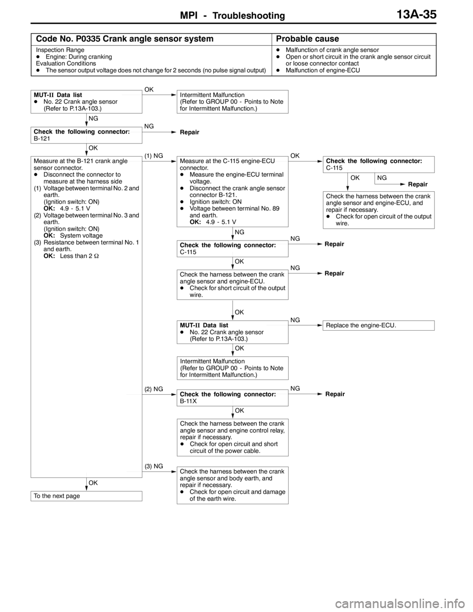
MPI -Troubleshooting13A-35
Code No. P0335 Crank angle sensor systemProbable cause
Inspection Range
DEngine: During cranking
Evaluation Conditions
DThe sensor output voltage does not change for 2 seconds (no pulse signal output)DMalfunction of crank angle sensor
DOpen or short circuit in the crank angle sensor circuit
or loose connector contact
DMalfunction of engine-ECU
OK
To the next page
(3) NGCheck the harness between the crank
angle sensor and body earth, and
repair if necessary.
DCheck for open circuit and damage
of the earth wire.
OK
Check the harness between the crank
angle sensor and engine control relay,
repair if necessary.
DCheck for open circuit and short
circuit of the power cable.
(2) NGCheck the following connector:
B-11XNG
Repair
OK
Intermittent Malfunction
(Refer to GROUP 00 - Points to Note
for Intermittent Malfunction.)
OK
MUT-IIData list
DNo. 22 Crank angle sensor
(Refer to P.13A-103.)NGReplace the engine-ECU. NG
OK
Check the harness between the crank
angle sensor and engine-ECU.
DCheck for short circuit of the output
wire.Repair
OK
Check the harness between the crank
angle sensor and engine-ECU, and
repair if necessary.
DCheck for open circuit of the output
wire.NG
Repair
NG
NG
Check the following connector:
C-115Repair
OK
Measure at the B-121 crank angle
sensor connector.
DDisconnect the connector to
measure at the harness side
(1) Voltage between terminal No. 2 and
earth.
(Ignition switch: ON)
OK:4.9 - 5.1 V
(2) Voltage between terminal No. 3 and
earth.
(Ignition switch: ON)
OK:System voltage
(3) Resistance between terminal No. 1
and earth.
OK:Less than 2Ω(1) NGMeasure at the C-115 engine-ECU
connector.
DMeasure the engine-ECU terminal
voltage.
DDisconnect the crank angle sensor
connector B-121.
DIgnition switch: ON
DVoltage between terminal No. 89
and earth.
OK:4.9 - 5.1 VOKCheck the following connector:
C-115
NG
Check the following connector:
B-121NG
Repair
MUT-IIData list
DNo. 22 Crank angle sensor
(Refer to P.13A-103.)OKIntermittent Malfunction
(Refer to GROUP 00 - Points to Note
for Intermittent Malfunction.)
Page 569 of 1449
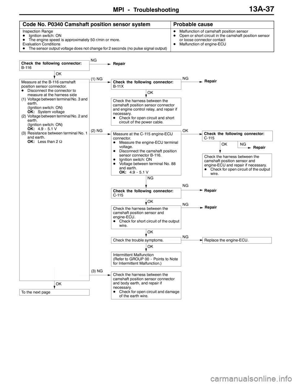
MPI -Troubleshooting13A-37
Code No. P0340 Camshaft position sensor systemProbable cause
Inspection Range
DIgnition switch: ON
DThe engine speed is approximately 50 r/min or more.
Evaluation Conditions
DThe sensor output voltage does not change for 2 seconds (no pulse signal output)DMalfunction of camshaft position sensor
DOpen or short circuit in the camshaft position sensor
or loose connector contact
DMalfunction of engine-ECU
OK
To the next page
(3) NGCheck the harness between the
camshaft position sensor connector
and body earth, and repair if
necessary.
DCheck for open circuit and damage
of the earth wire.
OK
Intermittent Malfunction
(Refer to GROUP 00 - Points to Note
for Intermittent Malfunction.)
OK
Check the trouble symptoms.NGReplace the engine-ECU.
OK
Check the harness between the
camshaft position sensor and
engine-ECU.
DCheck for short circuit of the output
wire.NG
Repair
NG
Check the following connector:
C-115NG
Repair
OK
Check the harness between the
camshaft position sensor and
engine-ECU and repair if necessary.
DCheck for open circuit of the output
wire.NG
Repair
(2) NGMeasure at the C-115 engine-ECU
connector.
DMeasure the engine-ECU terminal
voltage.
DDisconnect the camshaft position
sensor connector B-116.
DIgnition switch: ON
DVoltage between terminal No. 88
and earth.
OK:4.9 - 5.1 VOKCheck the following connector:
C-115
OK
Check the harness between the
camshaft position sensor connector
and engine control relay, and repair if
necessary.
DCheck for open circuit and short
circuit of the power cable.
OK
Measure at the B-116 camshaft
position sensor connector.
DDisconnect the connector to
measure at the harness side
(1) Voltage between terminal No. 3 and
earth.
(Ignition switch: ON)
OK:System voltage
(2) Voltage between terminal No. 2 and
earth.
(Ignition switch: ON)
OK:4.9 - 5.1 V
(3) Resistance between terminal No. 1
and earth.
OK:Less than 2Ω(1) NGCheck the following connector:
B-11XNG
Repair
Check the following connector:
B-116NG
Repair
Page 571 of 1449
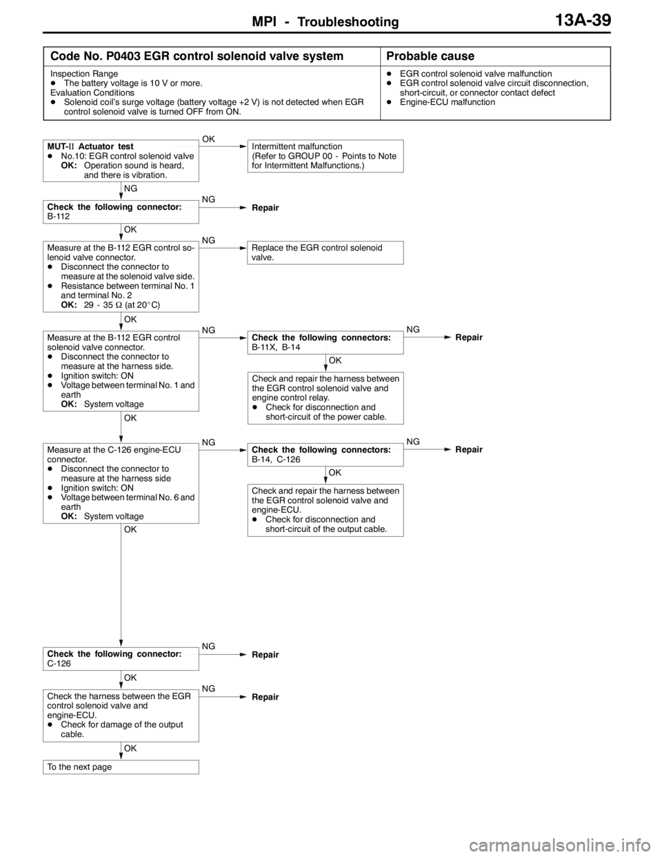
MPI -Troubleshooting13A-39
Code No. P0403 EGR control solenoid valve systemProbable cause
Inspection Range
DThe battery voltage is 10 V or more.
Evaluation Conditions
DSolenoid coil’s surge voltage (battery voltage +2 V) is not detected when EGR
control solenoid valve is turned OFF from ON.DEGR control solenoid valve malfunction
DEGR control solenoid valve circuit disconnection,
short-circuit, or connector contact defect
DEngine-ECU malfunction
OK
To the next page
OK
Check the harness between the EGR
control solenoid valve and
engine-ECU.
DCheck for damage of the output
cable.NG
Repair
OK
Check the following connector:
C-126NG
Repair
OK
Check and repair the harness between
the EGR control solenoid valve and
engine-ECU.
DCheck for disconnection and
short-circuit of the output cable.
OK
Measure at the C-126 engine-ECU
connector.
DDisconnect the connector to
measure at the harness side
DIgnition switch: ON
DVoltage between terminal No. 6 and
earth
OK:System voltageNGCheck the following connectors:
B-14, C-126NG
Repair
OK
Check and repair the harness between
the EGR control solenoid valve and
engine control relay.
DCheck for disconnection and
short-circuit of the power cable.
OK
Measure at the B-112 EGR control
solenoid valve connector.
DDisconnect the connector to
measure at the harness side.
DIgnition switch: ON
DVoltage between terminal No. 1 and
earth
OK:System voltageNGCheck the following connectors:
B-11X, B-14NG
Repair
OK
Measure at the B-112 EGR control so-
lenoid valve connector.
DDisconnect the connector to
measure at the solenoid valve side.
DResistance between terminal No. 1
and terminal No. 2
OK:29 - 35Ω(at 20_C)NGReplace the EGR control solenoid
valve.
NG
Check the following connector:
B-112NG
Repair
MUT-IIActuator test
DNo.10: EGR control solenoid valve
OK:Operation sound is heard,
and there is vibration.OKIntermittent malfunction
(Refer to GROUP 00 - Points to Note
for Intermittent Malfunctions.)
Page 573 of 1449
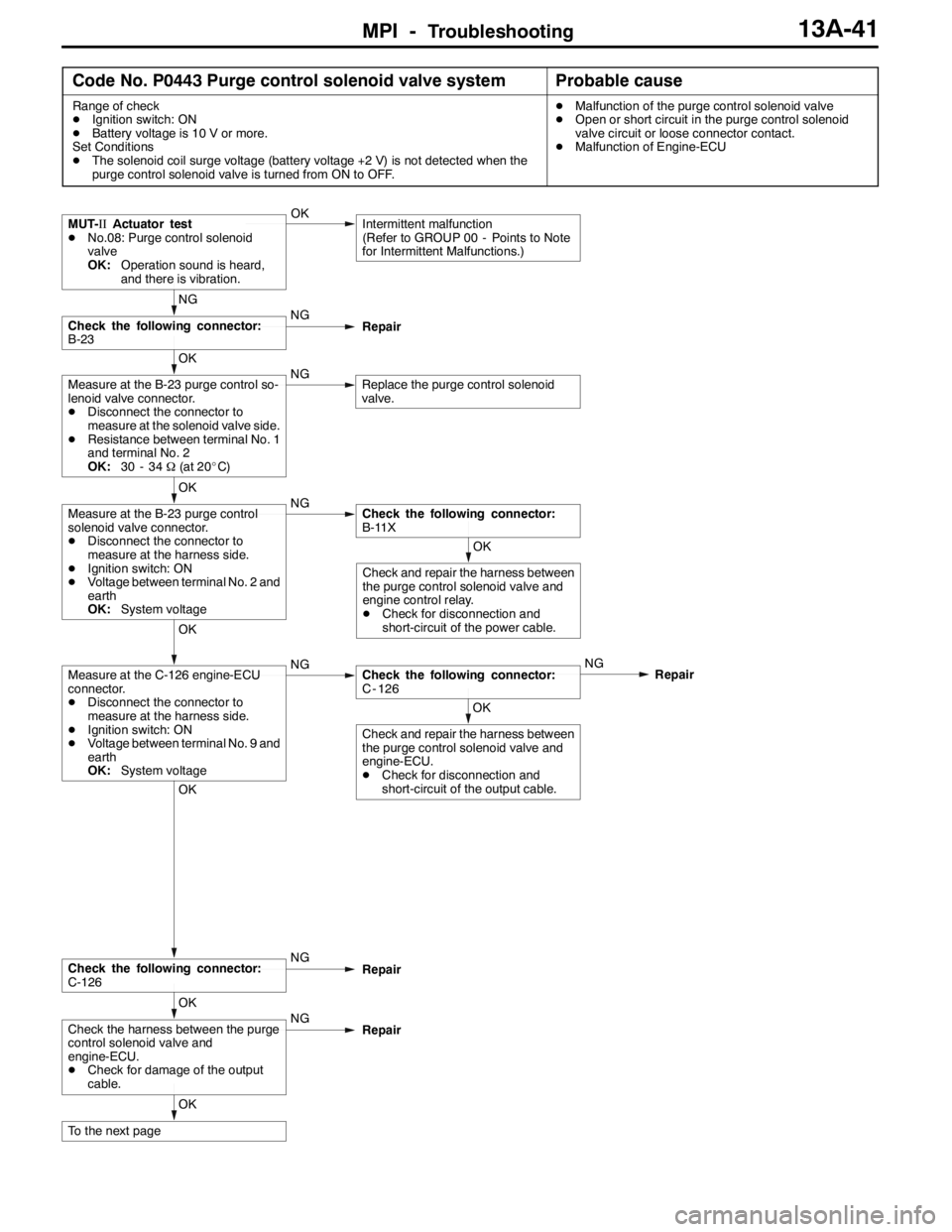
MPI -Troubleshooting13A-41
Code No. P0443 Purge control solenoid valve systemProbable cause
Range of check
DIgnition switch: ON
DBattery voltage is 10 V or more.
Set Conditions
DThe solenoid coil surge voltage (battery voltage +2 V) is not detected when the
purge control solenoid valve is turned from ON to OFF.DMalfunction of the purge control solenoid valve
DOpen or short circuit in the purge control solenoid
valve circuit or loose connector contact.
DMalfunction of Engine-ECU
OK
To the next page
OK
Check the harness between the purge
control solenoid valve and
engine-ECU.
DCheck for damage of the output
cable.NG
Repair
OK
Check the following connector:
C-126NG
Repair
OK
Check and repair the harness between
the purge control solenoid valve and
engine-ECU.
DCheck for disconnection and
short-circuit of the output cable.
OK
Measure at the C-126 engine-ECU
connector.
DDisconnect the connector to
measure at the harness side.
DIgnition switch: ON
DVoltage between terminal No. 9 and
earth
OK:System voltageNGCheck the following connector:
C - 126NG
Repair
OK
Check and repair the harness between
the purge control solenoid valve and
engine control relay.
DCheck for disconnection and
short-circuit of the power cable.
OK
Measure at the B-23 purge control
solenoid valve connector.
DDisconnect the connector to
measure at the harness side.
DIgnition switch: ON
DVoltage between terminal No. 2 and
earth
OK:System voltageNGCheck the following connector:
B-11X
OK
Measure at the B-23 purge control so-
lenoid valve connector.
DDisconnect the connector to
measure at the solenoid valve side.
DResistance between terminal No. 1
and terminal No. 2
OK:30 - 34Ω(at 20_C)NGReplace the purge control solenoid
valve.
NG
Check the following connector:
B-23NG
Repair
MUT-IIActuator test
DNo.08: Purge control solenoid
valve
OK:Operation sound is heard,
and there is vibration.OKIntermittent malfunction
(Refer to GROUP 00 - Points to Note
for Intermittent Malfunctions.)
Page 575 of 1449
MPI -Troubleshooting13A-43
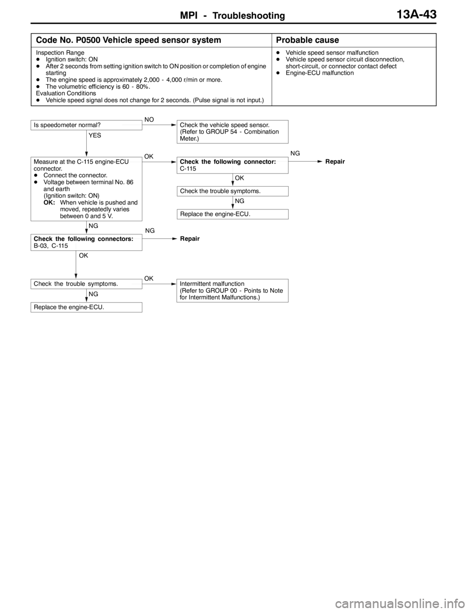
Code No. P0500 Vehicle speed sensor systemProbable cause
Inspection Range
DIgnition switch: ON
DAfter 2 seconds from setting ignition switch to ON position or completion of engine
starting
DThe engine speed is approximately 2,000 - 4,000 r/min or more.
DThe volumetric efficiency is 60 - 80%.
Evaluation Conditions
DVehicle speed signal does not change for 2 seconds. (Pulse signal is not input.)DVehicle speed sensor malfunction
DVehicle speed sensor circuit disconnection,
short-circuit, or connector contact defect
DEngine-ECU malfunction
NG
Replace the engine-ECU.
OK
Check the trouble symptoms.OKIntermittent malfunction
(Refer to GROUP 00 - Points to Note
for Intermittent Malfunctions.)
NG
Check the following connectors:
B-03, C-115
NG
Replace the engine-ECU.
OK
Check the trouble symptoms.
YES
Measure at the C-115 engine-ECU
connector.
DConnect the connector.
DVoltage between terminal No. 86
and earth
(Ignition switch: ON)
OK:When vehicle is pushed and
moved, repeatedly varies
between 0 and 5 V.OKCheck the following connector:
C-115NG
Repair
Is speedometer normal?NOCheck the vehicle speed sensor.
(Refer to GROUP 54 - Combination
Meter.)
NG
Repair
Page 576 of 1449

MPI -Troubleshooting13A-44
Code No. P0505 Idle speed control systemProbable cause
Range of Check
DVehicle speed has reached 1.5 Km/h at least once.
DUnder the closed loop idle speed control.
Set Conditions
DActual idle speed has continued to be higher than the target idle speed by 300
r/min or more for 10 seconds.
Range fo Check
DVehicle speed has reached 1.5 km/h at least once.
DDuring idle speed closed loop control.
DThe highest temperature at the last drive is 45_C or less.
DEngine coolant temperature is approximately 80_C or more.
DBattery voltage is 10 V or more.
DBarometric pressure is 76 kPa or higher.
DIntake air temperature is - 10_C or more.
Set Conitions
DActual idle speed has been minimum 200 r/min higher than the target idle speed
for 10 seconds.
Range of Check
DDuring idle speed closed loop control.
DEngine coolant temperature is approximately 80_C or higher.
DBattery voltage is 10 V or higher.
DPower steering switch is off.
DVolumetric efficiency is 40 % or lower.
DBarometric pressure is 76 kPa or higher.
DIntake air temperature is - 10_C or more.
Set Conitions
DActual idle speed has been minimum 100 r/min higher than the target idle speed
for 10 seconds.DMalfunction of idle speed control servo
DOpen or short circuit in the idle speed control servo
circuit or loose connector contact
DMalfunction of engine-ECU
Page 578 of 1449

MPI -Troubleshooting13A-46
Code No. P0551 Power steering fluid pressure switch
systemProbable cause
Range of Check
DIntake air temperature is - 10_C or higher.
DBarometric pressure is 76 kPa or more.
DEngine coolant temperature is 30_C or more.
DRepeat the *1 drive and *2 stop ten times or more.
*1: Engine speed is 2500 r/min or higher, volumetric efficiency is 55 % or higher and
vehicle speed is 5 km/h or higher for 4 seconds or more.
*2: Vehicle speed is 1.5 km/h or lower.
Set Conditions
DPower steering fluid pressure switch remains on.DPower steering fliud pressure switch failed
DOpen or short circuit in the power steering fluid
pressure switch circuit or loose conector contact
DMulfunction of engine-ECU
NG
OKOK
NGCheck the following connectors:
C-122, C-136
NG
OKNG
OK
Check the harness between the
power steering fluid pressure switch
and engine-ECU.
DCheck for short-circuit of the
output cable.Repair Repair
OKIntermittent malfunction (Refer to GROUP 00 - Points to Note
for Intermittent Malfunctions.)
NG
OK
Measure at the A-48 power steering
fluid pressure switch connector.
DDisconnect the connector to
measure at the harness side.
DIgnition switch: ON
DVoltage between terminal No. 1
and earth
OK:System voltageNGMeasure at the C-122 engine-ECU
connector.
DMeasure the engine-ECU terminal
voltage.
DIgnition switch: ON
DVoltage between terminal No. 37
and earth
OK:System voltage
OK
NG
Replace the engine-ECU.
MUT-IIData list
DNo. 27: Power steering fluid pressure switch (Refer to
P.13A-103.)
OK
Check the following connector:A-48NG
Repair
NG
Repair OK
Check the following connector:
C-126, C-136
Check and repair the harness
between the power steering fluid
pressure switch and engine-ECU.
DCheck for disconnection of the
output cable.
Replace the engine-ECU.
OK
NG
MUT-IIData list
DNo. 27: Power steering fluid
pressure switch (Refer to
P.13A-103.)Intermittent malfunction (Refer to
GROUP 00 - Points to Note for
Intermittent Malfunctions.)
Measure at the C-122 engine-ECU connector.
DMeasure the engine-ECU terminal voltage.
DEngine: Idling
DVoltage between terminal No. 37 and earth
DSteering wheel: Stationary state
OK:System voltage
DSteering wheel: Steered state
OK:1 V or less
OK
Replace the power steering fluid
pressure switch.Repair
Check the following connector:
C-122NG
Repair
Check the following connector:C-122
Check the harness between the
power steering fluid pressure switch
and engine-ECU.
DCheck for damage of the output
cable.OK
Repair NG
Page 579 of 1449
MPI -Troubleshooting13A-47
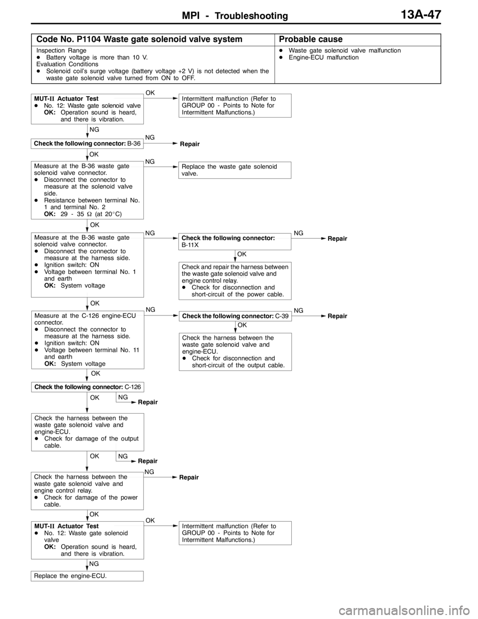
Code No. P1104 Waste gate solenoid valve systemProbable cause
Inspection Range
DBattery voltage is more than 10 V.
Evaluation Conditions
DSolenoid coil’s surge voltage (battery voltage +2 V) is not detected when the
waste gate solenoid valve turned from ON to OFF.DWaste gate solenoid valve malfunction
DEngine-ECU malfunction
OK
NG
Replace the engine-ECU.
OKIntermittent malfunction (Refer to
GROUP 00 - Points to Note for
Intermittent Malfunctions.)MUT-IIActuator Test
DNo. 12: Waste gate solenoid
valve
OK:Operation sound is heard,
and there is vibration.OKNG
Repair
OK
NG
Intermittent malfunction (Refer to
GROUP 00 - Points to Note for
Intermittent Malfunctions.)
OK
Check the following connector:B-36
MUT-IIActuator Test
DNo. 12: Waste gate solenoid valve
OK:Operation sound is heard,
and there is vibration.
NG
Repair
NGNG
Repair
OK
Check the harness between the
waste gate solenoid valve and
engine-ECU.
DCheck for disconnection and
short-circuit of the output cable.
Check the following connector:C-39
OK
Check the following connector:C-126
Measure at the C-126 engine-ECU
connector.
DDisconnect the connector to
measure at the harness side.
DIgnition switch: ON
DVoltage between terminal No. 11
and earth
OK:System voltageNG
Replace the waste gate solenoid
valve.Measure at the B-36 waste gate
solenoid valve connector.
DDisconnect the connector to
measure at the solenoid valve
side.
DResistance between terminal No.
1 and terminal No. 2
OK:29 - 35Ω(at 20_C)
OK
NG
Measure at the B-36 waste gate
solenoid valve connector.
DDisconnect the connector to
measure at the harness side.
DIgnition switch: ON
DVoltage between terminal No. 1
and earth
OK:System voltage
OKNG
Repair
OK
OK
Check and repair the harness between
the waste gate solenoid valve and
engine control relay.
DCheck for disconnection and
short-circuit of the power cable.
Check the following connector:
B-11X
NG
RepairCheck the harness between the
waste gate solenoid valve and
engine control relay.
DCheck for damage of the power
cable.NG
Repair
OK
Check the harness between the
waste gate solenoid valve and
engine-ECU.
DCheck for damage of the output
cable.