2007 MITSUBISHI LANCER EVOLUTION air condition
[x] Cancel search: air conditionPage 535 of 1449

MPI -General Information13A-3
GENERAL INFORMATION
The Multipoint Fuel Injection System consists
of sensors which detect the engine conditions,
the engine-ECU which controls the system
based on signals from these sensors, and
actuators which operate under the control of
the engine-ECU. The engine-ECU carries outactivities such as fuel injection control, idle
speed control and ignition timing control. In
addition, the engine-ECU is equipped with
several diagnosis modes which simplify
troubleshooting when a problem develops.
FUEL INJECTION CONTROL
The injector drive times and injector timing are
controlled so that the optimum air/fuel mixture
is supplied to the engine to correspond to the
continually-changing engine operation condi-
tions.
A single injector is mounted at the intake port
of each cylinder. Fuel is sent under pressure
from the fuel tank by the fuel pump, with the
pressure being regulated by the fuel pressure
regulator. The fuel thus regulated is distributed
to each of the injectors.
Fuel injection is normally carried out once for
each cylinder for every two rotations of the
crankshaft. The firing order is 1-3-4-2. This iscalled sequential fuel injection. The
engine-ECU provides a richer air/fuel mixture
by carrying out “open-loop” control when the
engine is cold or operating under high load
conditions in order to maintain engine
performance. In addition, when the engine is
warm or operating under normal conditions,
the engine-ECU controls the air/fuel mixture
by using the oxygen sensor signal to carry out
“closed-loop” control in order to obtain the
theoretical air/fuel mixture ratio that provides
the maximum cleaning performance from the
three way catalyst.
IDLE AIR CONTROL
The idle speed is kept at the optimum speed
by controlling the amount of air that bypasses
the throttle valve in accordance with changes
in idling conditions and engine load during
idling. The engine-ECU drives the idle speed
control motor to keep the engine running at
the pre-set idle target speed in accordance
with the engine coolant temperature and airconditioner load. In addition, when the air
conditioner switch is turned off and on while
the engine is idling, the idle speed control motor
operates to adjust the throttle valve bypass
air amount in accordance with the engine load
conditions in order to avoid fluctuations in the
engine speed.
IGNITION TIMING CONTROL
The power transistor located in the ignition
primary circuit turns ON and OFF to control
the primary current flow to the ignition coil. This
controls the ignition timing in order to provide
the optimum ignition timing with respect to theengine operating conditions. The ignition timing
is determined by the engine-ECU from the
engine speed, intake air volume, engine coolant
temperature and barometric pressure.
SELF-DIAGNOSIS FUNCTION
DWhen an abnormality is detected in one
of the sensors or actuators related to
emission control, the engine warning lamp
(check engine lamp) illuminates as a
warning to the driver.
DWhen an abnormality is detected in one
of the sensors or actuators, a diagnosis
code corresponding to the abnormality is
output.DThe RAM data inside the engine-ECU that
is related to the sensors and actuators can
be read by means of the MUT-II. In addition,
the actuators can be force-driven under
certain circumstances.
Page 543 of 1449

MPI -TroubleshootingMPI -Troubleshooting13A-11
CONFIRMING FREEZE FRAME DATA
When the engine-ECU detects a malfunction and stores a diagnosis code, it also stores a current status
of the engine. This function is called “Freeze frame” data. By analyzing this “Freeze frame” data with
MUT-II, an effective troubleshooting can be performed.
NOTE
If mulfunctions have been detected in multiple systems, engine-ECU stores one malfunction only, which
has been detected first.
Item No.Data itemUnit/StateItem No.Data itemUnit/State
21Engine coolant temperature
sensor_C81Learn value%
22Crank angle sensorr/min82Feedback%
24Vehicle speedkm/h87Engine load%
FAIL-SAFE FUNCTION REFERENCE TABLE
When the main sensor malfunctions are detected by the diagnosis function, the vehicle is controlled
by means of the pre-set control logic to maintain safe conditions for driving.
Malfunctioning itemControl contents during malfunction
Air flow sensor1. Uses the throttle position sensor signal and engine speed signal (crank angle sensor
signal) to take reading of the basic injector drive time and basic ignition timing from
the pre-set mapping.
2. Fixes the idle speed control servo in the appointed position so idle control is not
performed.
Intake air temperature
sensorControls as if the intake air temperature is 25_C.
Throttle position
sensorNo increase in fuel injection amount during acceleration due to the throttle position sensor
signal.
Engine coolant
temperature sensor1. Controls as if the engine coolant temperature is 80_C.
(Even after sensor signal is correctly recovered, continues until the ignition switch
is set to the “LOCK” (OFF) position.)
2. Rotates radiator fan and condenser fan at high speed.
Camshaft position
sensor1. Inject all fuel cylinders simultaneously. (However, when the No.1 cylinder top dead
centre is not detected at all after the ignition switch is turned to “ON” position.)
2. Shuts off fuel supply after 4 seconds have passed since a failure was detected.
(However, when the No.1 cylinder top dead centre is not detected at all after the
ignition switch is turned to “ON” position.)
Barometric pressure
sensorControls as if the barometric pressure is 101 kPa.
Detonation sensorSwitches the ignition timing from ignition timing for super petrol to ignition timing for standard
petrol.
Alternator FR terminalDoes not control the output of the alternator according to an electrical load. (works as a
normal alternator)
Page 545 of 1449
MPI -Troubleshooting13A-13
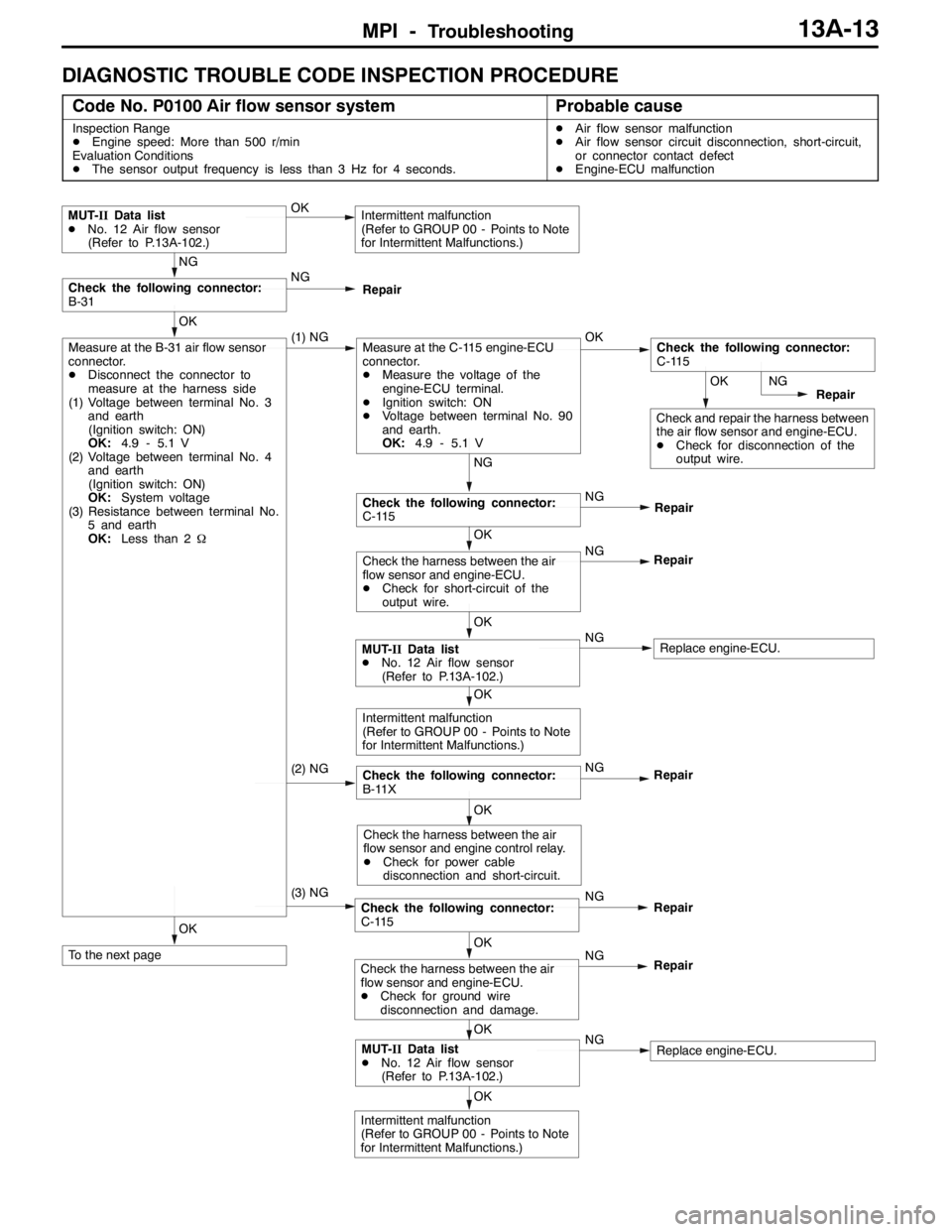
DIAGNOSTIC TROUBLE CODE INSPECTION PROCEDURE
Code No. P0100 Air flow sensor systemProbable cause
Inspection Range
DEngine speed: More than 500 r/min
Evaluation Conditions
DThe sensor output frequency is less than 3 Hz for 4 seconds.DAir flow sensor malfunction
DAir flow sensor circuit disconnection, short-circuit,
or connector contact defect
DEngine-ECU malfunction
OK
Intermittent malfunction
(Refer to GROUP 00 - Points to Note
for Intermittent Malfunctions.)
OK
MUT-IIData list
DNo. 12 Air flow sensor
(Refer to P.13A-102.)NGReplace engine-ECU.
OK
To the next pageOK
Check the harness between the air
flow sensor and engine-ECU.
DCheck for ground wire
disconnection and damage.NG
Repair
(3) NGCheck the following connector:
C-115NG
Repair
OK
Check the harness between the air
flow sensor and engine control relay.
DCheck for power cable
disconnection and short-circuit.
(2) NGCheck the following connector:
B-11XNG
OK
Intermittent malfunction
(Refer to GROUP 00 - Points to Note
for Intermittent Malfunctions.)
OK
MUT-IIData list
DNo. 12 Air flow sensor
(Refer to P.13A-102.)NGReplace engine-ECU.
OK
Check the harness between the air
flow sensor and engine-ECU.
DCheck for short-circuit of the
output wire.NG
Repair
NG
Check the following connector:
C-115NG
Repair
OK
Check and repair the harness between
the air flow sensor and engine-ECU.
DCheck for disconnection of the
output wire.NG
Repair
OK
Measure at the B-31 air flow sensor
connector.
DDisconnect the connector to
measure at the harness side
(1) Voltage between terminal No. 3
and earth
(Ignition switch: ON)
OK:4.9 - 5.1 V
(2) Voltage between terminal No. 4
and earth
(Ignition switch: ON)
OK:System voltage
(3) Resistance between terminal No.
5 and earth
OK:Less than 2Ω(1) NGMeasure at the C-115 engine-ECU
connector.
DMeasure the voltage of the
engine-ECU terminal.
DIgnition switch: ON
DVoltage between terminal No. 90
and earth.
OK:4.9 - 5.1 VOKCheck the following connector:
C-115
NG
Check the following connector:
B-31NG
Repair
MUT-IIData list
DNo. 12 Air flow sensor
(Refer to P.13A-102.)OKIntermittent malfunction
(Refer to GROUP 00 - Points to Note
for Intermittent Malfunctions.)
Repair
Page 547 of 1449
MPI -Troubleshooting13A-15
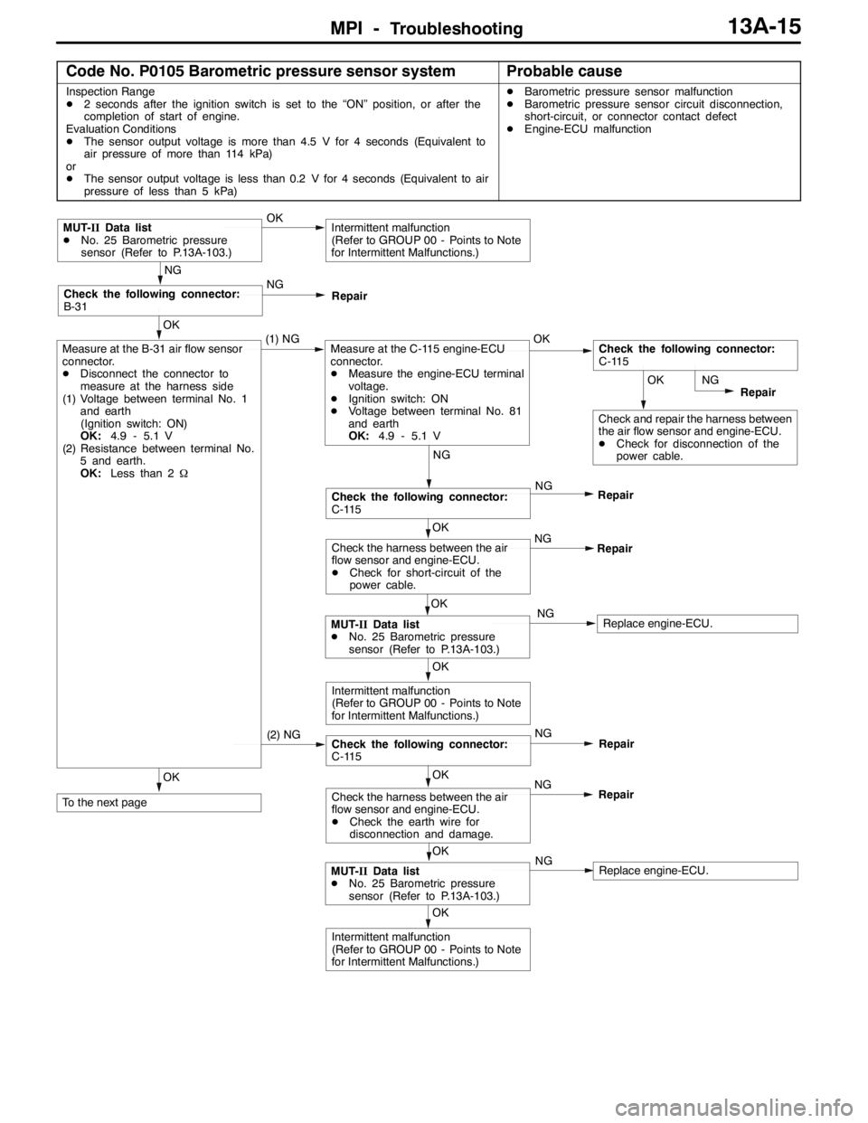
Code No. P0105 Barometric pressure sensor systemProbable cause
Inspection Range
D2 seconds after the ignition switch is set to the “ON” position, or after the
completion of start of engine.
Evaluation Conditions
DThe sensor output voltage is more than 4.5 V for 4 seconds (Equivalent to
air pressure of more than 114 kPa)
or
DThe sensor output voltage is less than 0.2 V for 4 seconds (Equivalent to air
pressure of less than 5 kPa)DBarometric pressure sensor malfunction
DBarometric pressure sensor circuit disconnection,
short-circuit, or connector contact defect
DEngine-ECU malfunction
OK
To the next page
OK
Intermittent malfunction
(Refer to GROUP 00 - Points to Note
for Intermittent Malfunctions.)
OK
MUT-IIData list
DNo. 25 Barometric pressure
sensor (Refer to P.13A-103.)NGReplace engine-ECU.
OK
Check the harness between the air
flow sensor and engine-ECU.
DCheck the earth wire for
disconnection and damage.NG
Repair
(2) NGCheck the following connector:
C-115NG
Repair
OK
Intermittent malfunction
(Refer to GROUP 00 - Points to Note
for Intermittent Malfunctions.)
OK
MUT-IIData list
DNo. 25 Barometric pressure
sensor (Refer to P.13A-103.)NGReplace engine-ECU.
OK
Check the harness between the air
flow sensor and engine-ECU.
DCheck for short-circuit of the
power cable.NG
Repair
NG
Check the following connector:
C-115NG
Repair
OK
Check and repair the harness between
the air flow sensor and engine-ECU.
DCheck for disconnection of the
power cable.NG
Repair
OK
Measure at the B-31 air flow sensor
connector.
DDisconnect the connector to
measure at the harness side
(1) Voltage between terminal No. 1
and earth
(Ignition switch: ON)
OK:4.9 - 5.1 V
(2) Resistance between terminal No.
5 and earth.
OK:Less than 2Ω(1) NGMeasure at the C-115 engine-ECU
connector.
DMeasure the engine-ECU terminal
voltage.
DIgnition switch: ON
DVoltage between terminal No. 81
and earth
OK:4.9 - 5.1 VOKCheck the following connector:
C-115
NG
Check the following connector:
B-31NG
Repair
MUT-IIData list
DNo. 25 Barometric pressure
sensor (Refer to P.13A-103.)OKIntermittent malfunction
(Refer to GROUP 00 - Points to Note
for Intermittent Malfunctions.)
Page 548 of 1449
MPI -Troubleshooting13A-16
OK
Intermittent malfunction
(Refer to GROUP 00 - Points to Note
for Intermittent Malfunctions.)
OK
MUT-IIData list
DNo. 25 Barometric pressure
sensor (Refer to P.13A-103.)NGReplace engine-ECU.
OK
Check the following connector:
C-115NG
Repair
OK
Check and repair the harness between
the air flow sensor and engine-ECU.
DCheck for disconnection and
damage of the output wire.
OK
Measure at the C-115 engine-ECU
connector.
DMeasure the engine-ECU terminal
voltage.
DIgnition switch: ON
DVoltage between terminal No. 85
and earth.
OK:High 0 m 3.8 - 4.2 V
High 600 m 3.5 - 3.9 V
High 1,200 m 3.3 - 3.7 V
High 1,800 m 3.0 - 3.4 VNGCheck the following connector:
C-115NGRepair
OK
Replace the air flow sensor.
OK
Check the harness between the air
flow sensor and engine-ECU.
DCheck for short-circuit and
damage of the output wire.NG
Repair
(3) NGCheck the following connector:
C-115NG
Repair
OK
Check and repair the harness between
the air flow sensor and engine-ECU.
DCheck for damage of the power
cable.
DCheck for damage of the earth
wire.
OK
Measure at the B-31 air flow sensor
connector.
DUsing the test harness
(MB991709), connect only
connector terminals No. 1, No. 2,
and No. 5, and measure at the
pickup harness.
DIgnition switch: ON
(1) Voltage between terminal No. 1
and earth
OK:4.9 - 5.1 V
(2) Voltage between terminal No. 5
and earth
OK:Less than 0.5 V
(3) Voltage from No. 2 to earth
OK:High 0 m 3.8 - 4.2 V
High 600 m 3.5 - 3.9 V
High 1,200 m 3.3 - 3.7 V
High 1,800 m 3.0 - 3.4 V(1), (2) NGCheck the following connectors:
C-115NGRepair
From the previous page
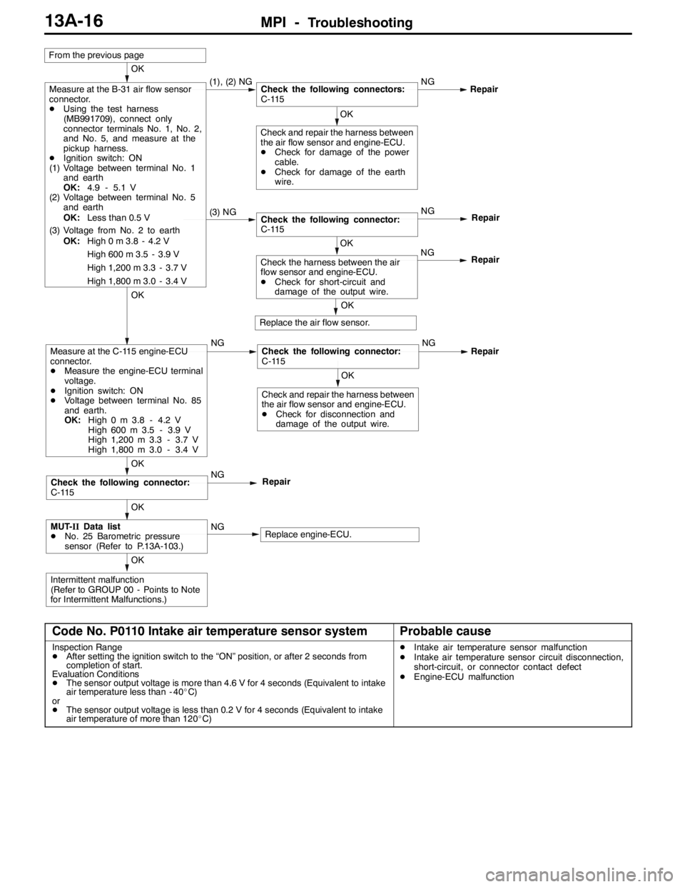
Code No. P0110 Intake air temperature sensor systemProbable cause
Inspection Range
DAfter setting the ignition switch to the “ON” position, or after 2 seconds from
completion of start.
Evaluation Conditions
DThe sensor output voltage is more than 4.6 V for 4 seconds (Equivalent to intake
air temperature less than - 40_C)
or
DThe sensor output voltage is less than 0.2 V for 4 seconds (Equivalent to intake
air temperature of more than 120_C)DIntake air temperature sensor malfunction
DIntake air temperature sensor circuit disconnection,
short-circuit, or connector contact defect
DEngine-ECU malfunction
Page 551 of 1449
MPI -Troubleshooting13A-19
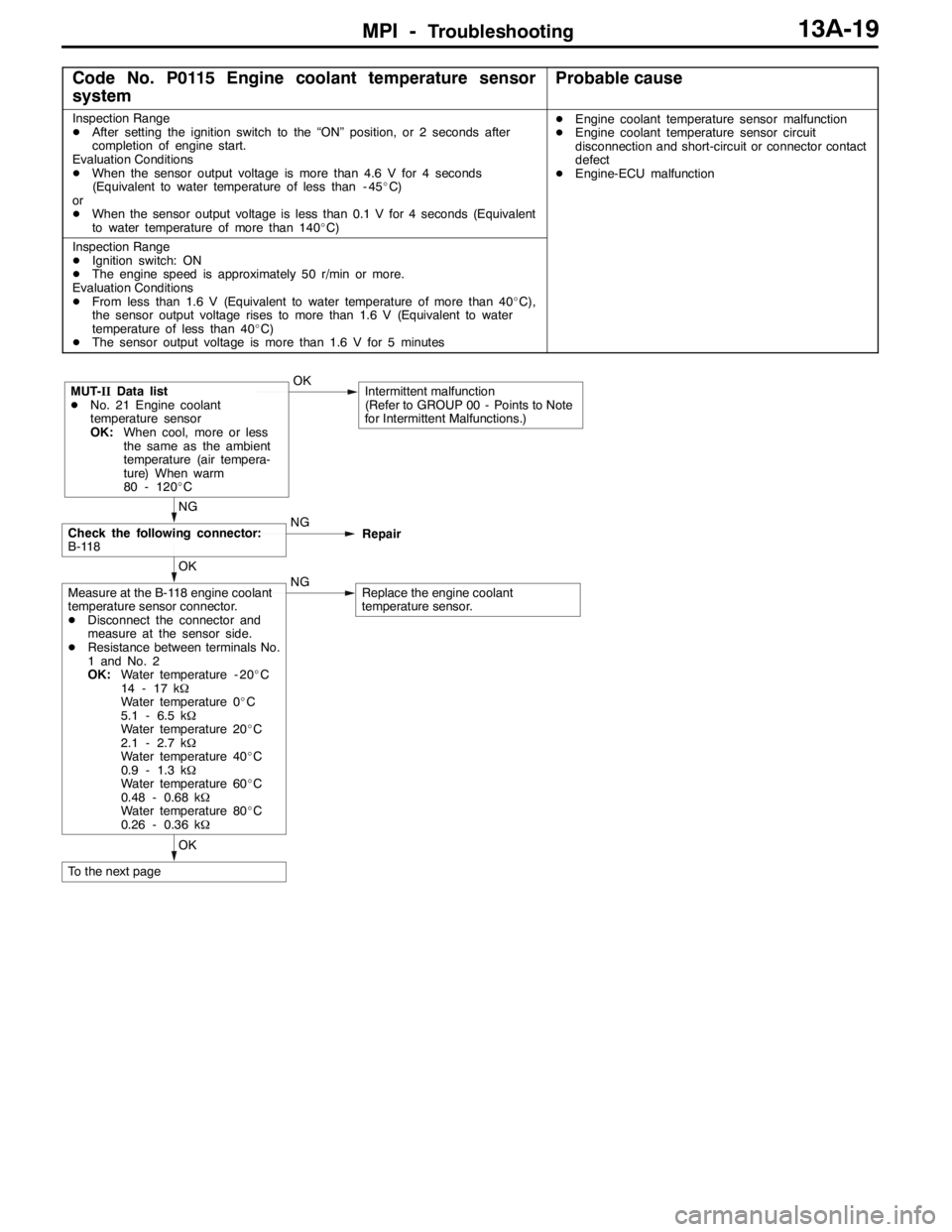
Code No. P0115 Engine coolant temperature sensor
systemProbable cause
Inspection Range
DAfter setting the ignition switch to the “ON” position, or 2 seconds after
completion of engine start.
Evaluation Conditions
DWhen the sensor output voltage is more than 4.6 V for 4 seconds
(Equivalent to water temperature of less than - 45_C)
or
DWhen the sensor output voltage is less than 0.1 V for 4 seconds (Equivalent
to water temperature of more than 140_C)DEngine coolant temperature sensor malfunction
DEngine coolant temperature sensor circuit
disconnection and short-circuit or connector contact
defect
DEngine-ECU malfunction
Inspection Range
DIgnition switch: ON
DThe engine speed is approximately 50 r/min or more.
Evaluation Conditions
DFrom less than 1.6 V (Equivalent to water temperature of more than 40_C),
the sensor output voltage rises to more than 1.6 V (Equivalent to water
temperature of less than 40_C)
DThe sensor output voltage is more than 1.6 V for 5 minutes
OK
To the next page
OK
Measure at the B-118 engine coolant
temperature sensor connector.
DDisconnect the connector and
measure at the sensor side.
DResistance between terminals No.
1 and No. 2
OK:Water temperature - 20_C
14 - 17 kΩ
Water temperature 0_C
5.1 - 6.5 kΩ
Water temperature 20_C
2.1 - 2.7 kΩ
Water temperature 40_C
0.9 - 1.3 kΩ
Water temperature 60_C
0.48 - 0.68 kΩ
Water temperature 80_C
0.26 - 0.36 kΩNGReplace the engine coolant
temperature sensor.
NG
Check the following connector:
B-118NG
Repair
MUT-IIData list
DNo. 21 Engine coolant
temperature sensor
OK:When cool, more or less
the same as the ambient
temperature (air tempera-
ture) When warm
80 - 120_COKIntermittent malfunction
(Refer to GROUP 00 - Points to Note
for Intermittent Malfunctions.)
Page 553 of 1449
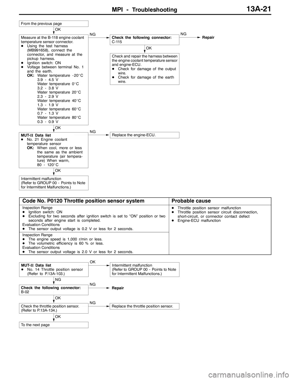
MPI -Troubleshooting13A-21
OK
Intermittent malfunction
(Refer to GROUP 00 - Points to Note
for Intermittent Malfunctions.)
OK
MUT-IIData list
DNo. 21 Engine coolant
temperature sensor
OK:When cool, more or less
the same as the ambient
temperature (air tempera-
ture) When warm,
80 - 120_CNGReplace the engine-ECU.
OK
Check and repair the harness between
the engine coolant temperature sensor
and engine-ECU.
DCheck for damage of the output
wire.
DCheck for damage of the earth
wire.
OK
Measure at the B-118 engine coolant
temperature sensor connector.
DUsing the test harness
(MB991658), connect the
connector, and measure at the
pickup harness.
DIgnition switch: ON
DVoltage between terminal No. 1
and the earth.
OK:Water temperature - 20_C
3.9 - 4.5 V
Water temperature 0_C
3.2 - 3.8 V
Water temperature 20_C
2.3 - 2.9 V
Water temperature 40_C
1.3 - 1.9 V
Water temperature 60_C
0.7 - 1.3 V
Water temperature 80_C
0.3 - 0.9 VNGCheck the following connector:
C-115NG
Repair
From the previous page
Code No. P0120 Throttle position sensor systemProbable cause
Inspection Range
DIgnition switch: ON
DExcluding for two seconds after ignition switch is set to “ON” position or two
seconds after engine start is completed.
Evaluation Conditions
DThe sensor output voltage is 0.2 V or less for 2 seconds.DThrottle position sensor malfunction
DThrottle position sensor circuit disconnection,
short-circuit, or connector contact defect
DEngine-ECU malfunction
Inspection Range
DThe engine speed is 1,000 r/min or less.
DThe volumetric efficiency is 60 % or less.
Evaluation Conditions
DThe sensor output voltage is 2.0 V or less for 2 seconds.
OK
To the next page
OK
Check the throttle position sensor.
(Refer to P.13A-134.)NGReplace the throttle position sensor.
NG
Check the following connector:
B-02NG
Repair
MUT-IIData list
DNo. 14 Throttle position sensor
(Refer to P.13A-103.)OKIntermittent malfunction
(Refer to GROUP 00 - Points to Note
for Intermittent Malfunctions.)
Page 556 of 1449
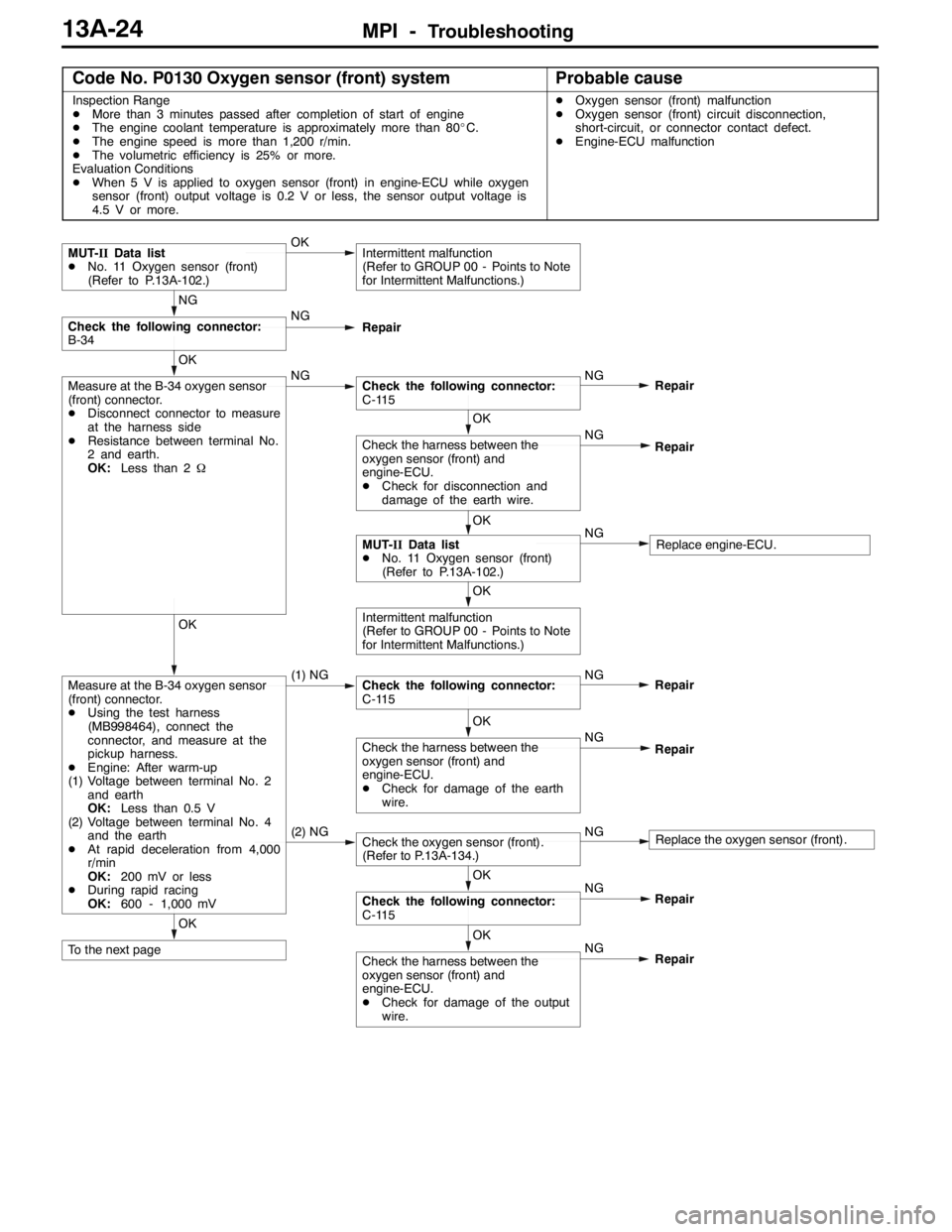
MPI -Troubleshooting13A-24
Code No. P0130 Oxygen sensor (front) systemProbable cause
Inspection Range
DMore than 3 minutes passed after completion of start of engine
DThe engine coolant temperature is approximately more than 80_C.
DThe engine speed is more than 1,200 r/min.
DThe volumetric efficiency is 25% or more.
Evaluation Conditions
DWhen 5 V is applied to oxygen sensor (front) in engine-ECU while oxygen
sensor (front) output voltage is 0.2 V or less, the sensor output voltage is
4.5 V or more.DOxygen sensor (front) malfunction
DOxygen sensor (front) circuit disconnection,
short-circuit, or connector contact defect.
DEngine-ECU malfunction
OK
To the next pageOK
Check the harness between the
oxygen sensor (front) and
engine-ECU.
DCheck for damage of the output
wire.NG
Repair NG
OK
Check the following connector:
C-115Repair
(2) NGCheck the oxygen sensor (front).
(Refer to P.13A-134.)NGReplace the oxygen sensor (front).
OK
Check the harness between the
oxygen sensor (front) and
engine-ECU.
DCheck for damage of the earth
wire.NG
Repair
OK
Measure at the B-34 oxygen sensor
(front) connector.
DUsing the test harness
(MB998464), connect the
connector, and measure at the
pickup harness.
DEngine: After warm-up
(1) Voltage between terminal No. 2
and earth
OK:Less than 0.5 V
(2) Voltage between terminal No. 4
and the earth
DAt rapid deceleration from 4,000
r/min
OK:200 mV or less
DDuring rapid racing
OK:600 - 1,000 mV(1) NGCheck the following connector:
C-115NG
Repair
OK
Intermittent malfunction
(Refer to GROUP 00 - Points to Note
for Intermittent Malfunctions.)
OK
MUT-IIData list
DNo. 11 Oxygen sensor (front)
(Refer to P.13A-102.)NGReplace engine-ECU.
OK
Check the harness between the
oxygen sensor (front) and
engine-ECU.
DCheck for disconnection and
damage of the earth wire.NG
Repair
OK
Measure at the B-34 oxygen sensor
(front) connector.
DDisconnect connector to measure
at the harness side
DResistance between terminal No.
2 and earth.
OK:Less than 2ΩNGCheck the following connector:
C-115NG
Repair
NG
Check the following connector:
B-34NG
Repair
MUT-IIData list
DNo. 11 Oxygen sensor (front)
(Refer to P.13A-102.)OKIntermittent malfunction
(Refer to GROUP 00 - Points to Note
for Intermittent Malfunctions.)