Page 1031 of 1449

FRONT SUSPENSION -On-vehicle Service33A-5
Tightening torque: 52±2 N·m
3. Confirm that the toe-in is at the standard value.
4. Use a turning radius gauge to check that the steering
angle is at the standard value.
Standard value:
Inner wheels31_45’±1_30’
Outer wheels (for reference)27_15’
TOE-OUT ANGLE ON TURNS
To check the steering linkage, especially after the vehicle
has been involved in an accident or if an accident is presumed,
it is advisable to check the toe-out angle on turns in addition
to the wheel alignment.
Conduct this test on the left turn as well as on the right turn.
Standard value:
ItemsSpecifications
Toe-out angle on turns
(inner wheel when outer wheel at 20_)22_00’±1_30’
CAMBER, CASTER AND KINGPIN INCLINATION
Standard value:
ItemsSpecifications
Camber
(Selectable from 2 options)-1_00’±30’* or - 2_00’±30’*
Caster3_55’±30’*
Kingpin inclination13_45’±1_30’
NOTE
1. *: difference between right and left wheels must be less
than 30’
2. Caster and kingpin inclination are preset at the factory
and cannot be adjusted.
SELECTION THE CAMBER
Select the camber by the installation direction of the allow
of the connecting bolt of the strut assembly and the knuckle.
D-1
_00’±30’: Install the bolt turning the allow to the direction
of vehicle inside.
D-2
_00’±30’: Install the bolt turning the allow to the direction
of vehicle outside.
BALL JOINT DUST COVER CHECK
1. Check the dust cover for cracks or damage by pushing
it with finger.
2. If the dust cover is cracked or damaged, replace the
lower arm assembly.
NOTE
Cracks or damage of the dust cover may cause damage
of the ball joint.
Page 1038 of 1449

FRONT SUSPENSION -Lower Arm Assembly/Stabilizer Bar33A-12
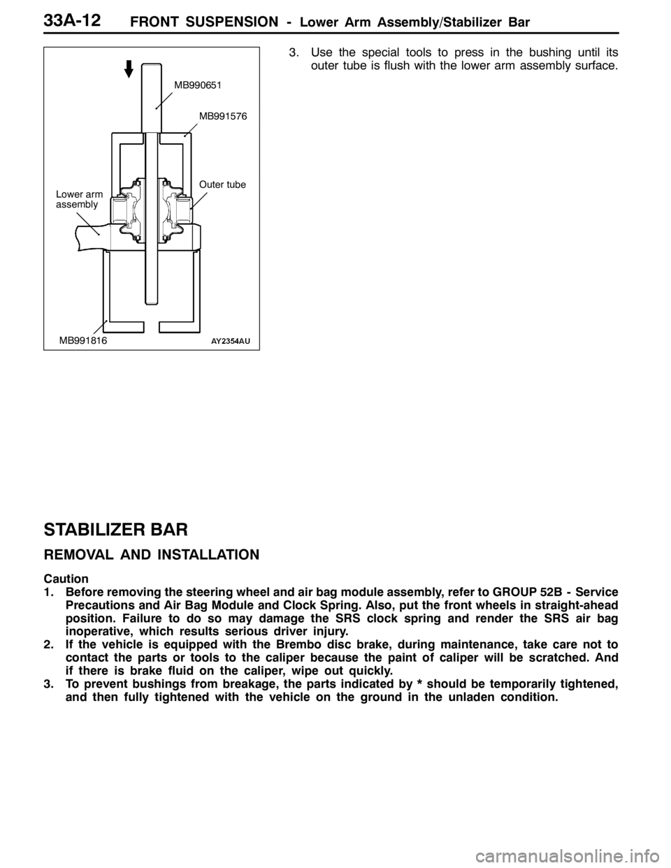
3. Use the special tools to press in the bushing until its
outer tube is flush with the lower arm assembly surface.
STABILIZER BAR
REMOVAL AND INSTALLATION
Caution
1. Before removing the steering wheel and air bag module assembly, refer to GROUP 52B - Service
Precautions and Air Bag Module and Clock Spring. Also, put the front wheels in straight-ahead
position. Failure to do so may damage the SRS clock spring and render the SRS air bag
inoperative, which results serious driver injury.
2. If the vehicle is equipped with the Brembo disc brake, during maintenance, take care not to
contact the parts or tools to the caliper because the paint of caliper will be scratched. And
if there is brake fluid on the caliper, wipe out quickly.
3. To prevent bushings from breakage, the parts indicated by * should be temporarily tightened,
and then fully tightened with the vehicle on the ground in the unladen condition.
Lower arm
assembly
MB990651
MB991576
MB991816
Outer tube
Page 1039 of 1449

FRONT SUSPENSION -Stabilizer Bar33A-13
Pre-removal Operation
DSteering Wheel and Air Bag Module Assembly
Removal (Refer to GROUP 37A.)
DClock Spring Removal (Refer to GROUP 52B.)
DCrossmember Bar Removal (Refer to P.33A-15.)
DCentermember Removal (Refer to GROUP 32.)
DFront Exhaust Pipe Removal (Refer to GROUP 15.)Post-installation Operation
DFront Exhaust Pipe Installation (Refer to GROUP
15.)
DCentermember Installation (Refer to GROUP 32.)
DCrossmember Bar Installation (Refer to P.33A-15.)
DClock Spring Installation (Refer to GROUP 52B.)
DSteering Wheel and Air Bag Module Assembly
Installation (Refer to GROUP 37A.)
DCheck the Dust Cover for Cracks or Damage by
Pushing it with Finger.
DChecking Steering Wheel Position with Wheels
Straight Ahead
DFront Wheel Alignment Check and Adjustment
(Refer to P.33A-4.)
3
4
10
21±4N·m
51
1
2
25±5N·m
18±2N·m
108±10 N·m
52±7N·m*
49±10 N·m
167±9N·m
7
8
9
6
39±5N·m
39±5N·m
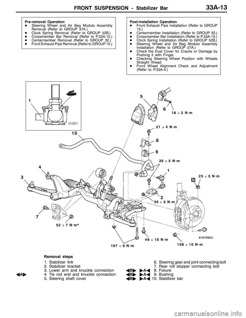
Removal steps
1. Stabilizer link
2. Stabilizer bracket
3. Lower arm and knuckle connection
AA"4. Tie rod end and knuckle connection
5. Steering shaft cover6. Steering gear and joint connecting bolt
7. Rear roll stopper connecting bolt
AB""AA8. Fixture
AB""AA9. Bushing
AB""AA10. Stabilizer bar
Page 1071 of 1449

35B-1
ANTI-SKID
BRAKING SYSTEM
(ABS) <4WD>
CONTENTS
GENERAL INFORMATION 2..................
SERVICE SPECIFICATIONS 3.................
LUBRICANTS Refer to GROUP 35A..........
SEALANT Refer to GROUP 35A..............
SPECIAL TOOLS 4...........................
TROUBLESHOOTING 4.......................
ON-VEHICLE SERVICE 26....................
Brake Pedal Check and Adjustment
Refer to GROUP 35A ..........................
Brake Booster Operating Test
Refer to GROUP 35A ..........................
Check Valve Operation Check
Refer to GROUP 35A ..........................
Bleeding Refer to GROUP 35A..................
Brake Fluid Level Sensor Check
Refer to GROUP 35A ..........................
Disc Brake Pad Check and
Replacement Refer to GROUP 35A..............Disc Brake Rotor Check Refer to GROUP 35A...
Brake Disc Thickness Check
Refer to GROUP 35A ..........................
Brake Disc Run-out Check and Correction
Refer to GROUP 35A ..........................
Wheel Speed Sensor Output Voltage Check
26 ............................................
Hydraulic Unit Check 28........................
Remedy for a Flat Battery 29...................
BRAKE PEDAL Refer to GROUP 35A........
MASTER CYLINDER AND BRAKE
BOOSTER Refer to GROUP 35A............
DISC BRAKE Refer to GROUP 35A..........
HYDRAULIC UNIT AND ABS-ECU 30.........
WHEEL SPEED SENSOR 33..................
G SENSORS AND STEERING WHEEL
SENSOR 35..................................
Page 1072 of 1449

ABS <4WD> -General Information35B-2
GENERAL INFORMATION
ABS has been adopted as optional equipment in
RS-IIto maintain directional stability and steering
performance during sudden braking or braking on
slippery road surfaces.
The ABS control method is a 4-sensor, 4-channel
method which provides independent control for all
wheels.
Following system for Lancer EVOLUTION-VII has
been modified from Lancer EVOLUTION-VI Tommi
Makinen Edition.DBy adding lateral G sensor, longitudinal G
sensor and steering wheel sensor, optimized
ABS control at the time of cornering.
DBy inputting parking brake switch signal to
ABS-ECU with pulling parking brake lever, ABS
control has been optimized.
DABS-ECU outputs ABS signal to 4WD-ECU.
DG sensor (lateral), steering wheel sensor and
parking brake switch have been added to the
diagnosis and service data.
DABS-ECU connector has been changed.
EBD CONTROL
In ABS, electronic control method is used by which
the rear wheel brake hydraulic pressure during
braking is regulated by rear wheel control solenoid
valves in accordance with the vehicle’s rate of
deceleration and the front and rear wheel slippage
which are calculated from the each wheel speed
sensor’s signal. EBD control is a control system
which provides a high level of control for both vehicle
braking force and vehicle stability. The system has
the following features:
DBecause the system provides the optimum rear
wheel braking force regardless of the vehicleladen condition and the condition of the road
surface, the system reduces the required pedal
depression force, particularly when the vehicle
is heavily laden or driving on road surfaces
with high frictional coefficients.
DBecause the duty placed on the front brakes
has been reduced, the increases in pad
temperature can be controlled to improve the
wear resistance characteristics of the pad,
during front brakes applying.
DControl valves such as the proportioning valve
are no longer required.
SPECIFICATIONS
ItemSpecifications
ABS control method4-sensor, 4-channel
No. of ABS rotor teethFront43
Rear43
ABS speed sensorTypeMagnet coil typep
Gap between sensor and rotor mm0.85 / 0.60 (non-adjustable type)
Page 1073 of 1449
ABS <4WD> -General Information/Service Specifications35B-3
CONSTRUCTION DIAGRAM
Stop lamp
switch*Parking brake
switch
Diagnosis
connector*
Wheel speed sensorWheel speed sensor Hydraulic unit
assembly*
(integrated with
the ABS-ECU) ABS warning lamp
Lateral G sensor
Longitudinal G sensor Steering
wheel
sensor*
NOTE
For R.H. drive vehicles, only the position indicated by the * is symmetrical.
SERVICE SPECIFICATIONS
ItemsStandard value
Wheel speed sensor internal resistance kΩ1.24 - 1.64
Wheel speed sensor insulation resistance kΩ100 or more
Lateral G sensor/Longitudinal G
sensoroutputvoltageV
On stationary vehicle2.4 - 2.6
sensor outputvoltageV
With front mark downward3.4 - 3.6
Page 1078 of 1449
ABS <4WD> -Troubleshooting35B-8
Diagnosis code No.Reference page Inspection item
81Steering wheel sensor (ST-1) system (Open circuit or short circuit)35B-14
82Steering wheel sensor (ST-2) system (Open circuit or short circuit)
83Steering wheel sensor (ST-N) system (Open circuit or short circuit)
NOTE: diagnosis code No.16, 52, 63
1. Code No. 16 is cleared from the memory by turning the ignition switch to ACC position. When the system
is properly reset, this code is also cleared from the memory.
2. Code No. 52 and 63 are cleared from the memory by turning the ignition switch to ACC position.
Page 1084 of 1449

ABS <4WD> -Troubleshooting35B-14
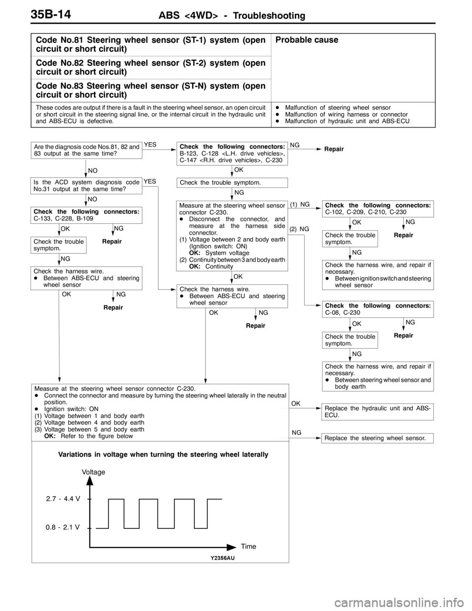
Code No.81 Steering wheel sensor (ST-1) system (open
circuit or short circuit)Probable cause
Code No.82 Steering wheel sensor (ST-2) system (open
circuit or short circuit)
Code No.83 Steering wheel sensor (ST-N) system (open
circuit or short circuit)
These codes are output if there is a fault in the steering wheel sensor, an open circuit
or short circuit in the steering signal line, or the internal circuit in the hydraulic unit
and ABS-ECU is defective.DMalfunction of steering wheel sensor
DMalfunction of wiring harness or connector
DMalfunction of hydraulic unit and ABS-ECU
NG
Repair
Replace the hydraulic unit and ABS-
ECU. OK NG YES
Repair
NOAre the diagnosis code Nos.81, 82 and
83 output at the same time?
OKCheck the following connectors:
B-123, C-128 ,
C-147 , C-230
YES
NO
Is the ACD system diagnosis code
No.31 output at the same time?
NG
Check the trouble symptom.
(1) NG
(2) NGNG
Repair
NG
OK
Check the trouble
symptom.
Check the following connectors:
C-102, C-209, C-210, C-230
Check the harness wire, and repair if
necessary.
DBetween ignition switch and steering
wheel sensor
NG
OK
Check the trouble
symptom.
Check the following connectors:
C-08, C-230
Check the harness wire, and repair if
necessary.
DBetween steering wheel sensor and
body earth
OK
Measure at the steering wheel sensor
connector C-230.
DDisconnect the connector, and
measure at the harness side
connector.
(1) Voltage between 2 and body earth
(Ignition switch: ON)
OK:System voltage
(2) Continuity between 3 and body earth
OK:Continuity
NG
RepairOK
Check the harness wire.
DBetween ABS-ECU and steering
wheel sensor NG
Repair
NG OK
Check the trouble
symptom.
Check the following connectors:
C-133, C-228, B-109
NG
Repair
Check the harness wire.
DBetween ABS-ECU and steering
wheel sensor
OK
Replace the steering wheel sensor. NG
Time Voltage
2.7 - 4.4 V
0.8 - 2.1 V
Variations in voltage when turning the steering wheel laterally
Measure at the steering wheel sensor connector C-230.
DConnect the connector and measure by turning the steering wheel laterally in the neutral
position.
DIgnition switch: ON
(1) Voltage between 1 and body earth
(2) Voltage between 4 and body earth
(3) Voltage between 5 and body earth
OK:Refer to the figure below