2007 MITSUBISHI LANCER EVOLUTION steering wheel
[x] Cancel search: steering wheelPage 643 of 1449

MPI -Troubleshooting13A-111
Terminal No.Normal condition Check condition (Engine condition) Check item
37Power steering fluid
pressure switchEngine: Idling after
warming upWhen steering wheel
is stationarySystem voltage
When steering wheel
is turned1 V or less
38Engine control relayIgnition switch: “LOCK” (OFF)System voltage
Ignition switch: “ON”1 V or less
39Fuel pump relay 3While engine is idling, suddenly depress the
accelerator pedal.Temporarily rises slightly
from 1 V or less.
41Alternator FR
terminalDEngine: After warm-up, idle operation
DRadiator fan: Not operating
DHead lamp: OFF→ON
DStop lamp: OFF→ON
DRear deffogger switch: OFF→ONVoltage decrease
44Intercooler water
spray switch (Auto)DIgnition switch: “ON”
DIntercooler water spray switch: ON1 V or less
DIgnition switch: “ON”
DIntercooler water spray switch: OFFSystem voltage
45A/C switchEngine: Idle operationTurn the A/C switch
OFF0.5 V or less
DA/C switch: ON
DA/C setting
temperature
When room tem-
perature is 25_C
or more: Max
Cool
When room tem-
perature is 25_C
or less: Max. HotSystem voltage
53Secondary air control
solenoid valveIgnition switch: “ON”System voltage
54Oxygen sensor
heater(Rear)
Engine: Idling after warming up1 V or less
heater(Rear)
Engine speed: 5,000r/minSystem voltage
55Intercooler water
sprayrelay
Ignition switch: “ON”System voltage
spray relay
Ignition switch: “LOCK” (OFF)1 V or less
58Tachometer signalEngine speed: 3,000r/min0.3 - 3.0 V
60Oxygen sensor
heater(front)
Engine: Idling after warming up1 V or less
heater(front)
Engine speed: 5,000r/minSystem voltage
71Ignition switch - STEngine: Cranking8 V or more
Page 813 of 1449

MANUAL TRANSMISSION - Troubleshooting
TROUBLESHOOTING
BASIC TROUBLESHOOTING CONDITIONS
Refer to GROUP 00 - How to Use Troubleshooting/Inspection Service Points.
NOTE
Before starting the troubleshooting procedure, make sure that the following items have been checked
okay.
DIs the appropriate steering wheel installed at the center of the steering column shaft correctly?
DAre the tire, wheel size, specifications, air pressure, balance, and wear state normal?
DIs the wheel alignment normal?
DHas the engine, suspension, etc. been remodeled in such a way that it will affect the ACD and AYC
systems?
DIAGNOSIS FUNCTION
READING DIAGNOSIS CODE
Read a diagnosis code by the MUT-IIor ACD mode indicator
lamp. (Refer to GROUP 00 - How to Use Troubleshooting/
Inspection Service Points.)
NOTE
Connect the MUT-IIto the diagnosis connector (16-pin).
ERASING DIAGNOSIS CODES
When using the MUT-II
Connect the MUT-IIto the diagnosis connector (16-pin) and
erase the diagnosis code.
Caution
Turn the ignition switch to the “LOCK”(OFF) position
before connecting or disconnecting the MUT-II.
ACDmode indicator lamp
Page 814 of 1449

MANUAL TRANSMISSION - Troubleshooting
INSPECTION CHART FOR DIAGNOSIS CODES
Diagnosis
code No.Diagnosis itemsReference page
12Power supply voltage (valve power supply) systemopen circuit or short-circuit22A-8
13Fail-safe relay system
21Wheel speed sensor
22Wheel speed sensor
23Wheel speed sensor
24Wheel speed sensor
25Wrong-diameter tire22A-11
26Wheel speed sensor (faulty output signal)22A-13
31Steering wheel sensor
32Steering wheel sensor
33fixed22A-16
34Steering wheel sensor
fixed22A-17
41TPS systemopen circuit or ground22A-18
42short-circuit22A-18
45Pressure sensor systemopen circuit or ground22A-19
46open earth22A-19
47abnormal power supply22A-20
51Longitudinal G sensor systemopen circuit or short-circuit22A-21
52defective sensor22A-22
56Lateral G sensor systemopen circuit or short-circuit22A-23
57defective sensor22A-24
61Stop lamp switch systemopen circuit22A-25
62ACD mode switch systemstuck22A-26
63Parking brake switch systemshort-circuit or not re-
turned to original position22A-27
65ABS monitor systemopen circuit or defective
ABS22A-28
71Proportional valve
GROUP27B
72Directional control valve
GROUP27B.
73Directional control valve
74Proportional valve
Page 819 of 1449

MANUAL TRANSMISSION - Troubleshooting
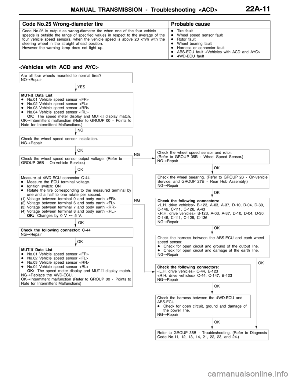
Code No.25 Wrong-diameter tireProbable cause
Code No.25 is output as wrong-diameter tire when one of the four vehicle
speeds is outside the range of specified values in respect to the average of the
four vehicle speed sensors, when the vehicle speed is above 20 km/h with the
steering wheel in the straight ahead position.
However the warning lamp does not light up.DTire fault
DWheel speed sensor fault
DRotor fault
DWheel bearing fault
DHarness or connector fault
DABS-ECU fault
D4WD-ECU fault
OK NG
OK
Check the following connector:C-44
NG→Repair
Check the following connectors:
NG→Repair OKYES
OK
OK
Check the wheel speed sensor and rotor.
(Refer to GROUP 35B - Wheel Speed Sensor.)
NG→Repair
Check the wheel speed sensor output voltage. (Refer to
GROUP 35B - On-vehicle Service.)OK
Check the wheel speed sensor installation.
NG→Repair
NG
OK
Check the wheel beearing. (Refer to GROUP 26 - On-vehicle
Service, and GROUP 27B - Rear Hub Assembly.)
NG→Repair
OK
Check the following connectors:
C-146, C-111, C-128, A-43
C-146, C-111, C-128, C-136
NG→Repair NG
MUT-IIData List
DNo.01 Vehicle speed sensor
DNo.02 Vehicle speed sensor
DNo.03 Vehicle speed sensor
DNo.04 Vehicle speed sensor
OK:The speed meter display and MUT-IIdisplay match.
OK→Intermittent malfunction (Refer to GROUP 00 - Points to
Note for Intermittent Malfunctions.)
Measure at 4WD-ECU connector C-44.
DMeasure the ECU terminal voltage.
DIgnition switch: ON
DRotate the tire corresponding to the measured terminal by
one and a half to one rotate per second.
(1) Voltage between terminal 9 and body earth
(2) Voltage between terminal 6 and body earth
(3) Voltage between terminal 7 and body earth
(4) Voltage between terminal 8 and body earth
OK:Changes by 0 V↔5V.
MUT-IIData List
DNo.01 Vehicle speed sensor
DNo.02 Vehicle speed sensor
DNo.03 Vehicle speed sensor
DNo.04 Vehicle speed sensor
OK:The speed meter display and MUT-IIdisplay match.
NG→Replace the 4WD-ECU.
OK→Intermittent malfunction (Refer to GROUP 00 - Points to
Note for Intermittent Malfunctions)
Refer to GROUP 35B - Troubleshooting. (Refer to Diagnosis
Code No.11, 12, 13, 14, 21, 22, 23, and 24.)
Are all four wheels mounted to normal tires?
NO→Repair
Check the harness between the ABS-ECU and each wheel
speed sensor.
DCheck for open circuit and ground of the output line.
DCheck for open circuit and damage of the earth line.
NG→Repair
OK
Check the harness between the 4WD-ECU and
ABS-ECU.
DCheck for open circuit, ground and damage of
the power line.
NG→RepairOK
Page 823 of 1449

MANUAL TRANSMISSION - Troubleshooting
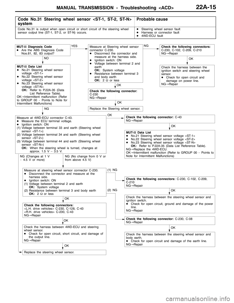
Code No.31 Steering wheel sensor
systemProbable cause
Code No.31 is output when open circuit or short circuit of the steering wheel
sensor output line (ST-1, ST-2, or ST-N) occurs.DSteering wheel sensor fault
DHarness or connector fault
D4WD-ECU fault
OK NG NO
OK
MUT-IIData List
DNo.21 Steering wheel sensor
voltage
DNo.22 Steering wheel sensor
voltage
DNo.23 Steering wheel sensor
voltage
OK:Refer to P.22A-35 (Data
List Reference Table).
OK→Intermittent malfunction (Refer
to GROUP 00 - Points to Note for
Intermittent Malfunctions)
Check the following connector:C-43
NG→Repair YES
MUT-IIDiagnosis Code
DAre the ABS Diagnosis Code
Nos.81, 82, 83 output?
MUT-IIData List
DNo.21 Steering wheel sensor voltage
DNo.22 Steering wheel sensor voltage
DNo.23 Steering wheel sensor voltage
OK:Refer to P.22A-35 (Data List Reference Table).
NG→Replace the 4WD-ECU.
OK→Intermittent malfunction (Refer to GROUP 00 - Points to
Note for Intermittent Malfunctions)
NG (No change from 0 V or
from above 4.5 V)
Measure at 4WD-ECU connector C-43.
DMeasure the ECU terminal voltage.
DIgnition switch: ON
(1) Voltage between terminal 33 and earth (Steering wheel
sensor
(2) Voltage between terminal34and earth (Steering wheel
sensor
(3) Voltage between terminal44 andearth (Steering wheel
sensor
OK:When the steering wheel is turned, changes at
approx. 1.5 V – 3.5 V.
(1) NG
NG (Changes at 1 V
- 4.5 V or more)
OK
Check the harness between the steering wheel sensor and
ignition switch.
DCheck for open circuit, ground and damage of the power
line.
NG→Repair
Check the following connectors:C-230, C-102, C-209,
C-210
NG→Repair
OKOK
Check the following connectors:
NG→Repair
OK
Check the harness between 4WD-ECU and steering
wheel sensor.
DCheck for open circuit, short circuit, and damage of
the output line.
NG→Repair
Replace the steering wheel sensor.
Replace the Steering wheel sensor.
OK
OK
Check the following connector:
C-230
NG→RepairNG
Measure at Steering wheel sensor
connector C-230.
DDisconnect the connector and
measure at the harness side.
DIgnition switch: ON
DVoltage between terminal 2 and
earth
OK:System voltage
DResistance between terminal 3
and body earth
OK:2Ωor less
OK
Check the following connectors:
C-230, C-102, C-209, C-210
NG→Repair
Check the harness between the
ignition switch and steering wheel
sensor.
DCheck for open circuit and
damage on power line.
NG→Repair
(2) NG
OK
Check the harness between the steering wheel sensor and
body earth.
DCheck for open circuit and damage of the earth line.
NG→Repair
Check the following connector:C-230, C-08
NG→Repair
Measure at steering wheel sensor connector C-230.
DDisconnect the connector and measure at the
harness side.
DIgnition switch: ON
(1) Voltage between terminal 2 and earth
OK:System voltage
(2) Resistance between terminal 3 and body earth
OK:2Ωor less
Page 824 of 1449

MANUAL TRANSMISSION - Troubleshooting
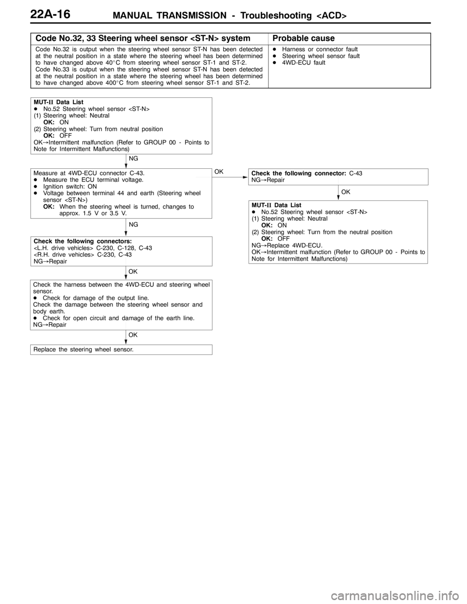
Code No.32, 33 Steering wheel sensor
Code No.32 is output when the steering wheel sensor ST-N has been detected
at the neutral position in a state where the steering wheel has been determined
to have changed above 40_C from steering wheel sensor ST-1 and ST-2.
Code No.33 is output when the steering wheel sensor ST-N has been detected
at the neutral position in a state where the steering wheel has been determined
to have changed above 400_C from steering wheel sensor ST-1 and ST-2.DHarness or connector fault
DSteering wheel sensor fault
D4WD-ECU fault
NG
OK
MUT-IIData List
DNo.52 Steering wheel sensor
(1) Steering wheel: Neutral
OK:ON
(2) Steering wheel: Turn from neutral position
OK:OFF
OK→Intermittent malfunction (Refer to GROUP 00 - Points to
Note for Intermittent Malfunctions)
Check the following connector:C-43
NG→Repair
NG
Check the following connectors:
NG→Repair
OK
Replace the steering wheel sensor.OK
Measure at 4WD-ECU connector C-43.
DMeasure the ECU terminal voltage.
DIgnition switch: ON
DVoltage between terminal 44 and earth (Steering wheel
sensor
OK:When the steering wheel is turned, changes to
approx. 1.5 V or 3.5 V.
MUT-IIData List
DNo.52 Steering wheel sensor
(1) Steering wheel: Neutral
OK:ON
(2) Steering wheel: Turn from the neutral position
OK:OFF
NG→Replace 4WD-ECU.
OK→Intermittent malfunction (Refer to GROUP 00 - Points to
Note for Intermittent Malfunctions)
OK
Check the harness between the 4WD-ECU and steering wheel
sensor.
DCheck for damage of the output line.
Check the damage between the steering wheel sensor and
body earth.
DCheck for open circuit and damage of the earth line.
NG→Repair
Page 825 of 1449

MANUAL TRANSMISSION - Troubleshooting
Code No.34 Steering wheel sensor
Code No.34 is output when no change in the steering wheel sensor signal at a
vehicle speed of above 15 km/h is detected for a total of more than 15 minutes
DSteering wheel sensor fault
D4WD-ECU fault
NG
OK
MUT-IIData List
DNo.53 Steering wheel sensor
OK:When the steering wheel is rotated to the left, ON
and OFF are repeated.
DNo.54 Steering wheel sensor
OK:When the steering wheel is rotated to the right, ON
and OFF are repeated.
OK→Intermittent malfunction (Refer to GROUP 00 - Points to
Note for Intermittent Malfunctions)
Check the following connector:C-43
NG→Repair
NG
Check the following connectors:
NG→Repair
OK
Replace the steering wheel sensor.OK
OK
Check the harness between the 4WD-ECU and steering wheel
sensor.
DCheck for damage of the output line.
Check the harness between the steering wheel sensor and
body earth.
DCheck for open circuit and damage of the earth line.
NG→Repair
Measure at 4WD-ECU connector C-43.
DMeasure the ECU terminal voltage.
DIgnition switch: ON
(1) Voltage between terminal 33 and earth (Steering wheel
sensor
(2) Voltage between terminal 34 and earth (Steering wheel
sensor
OK:When the steering wheel is turned, changes at
approx. 1.5 V or 3.5 V
MUT-IIData List
DNo.53 Steering wheel sensor
OK:When the steering wheel is rotated to the left, ON
and OFF are repeated
DNo.54 Steering wheel sensor
OK:When the steering wheel is rotated to the right ON
and OFF are repeated.
NG→Replace the 4WD-ECU.
OK→Intermittent malfunction (Refer to GROUP 00 - Points to
Note for Intermittent Malfunctions.)
Page 843 of 1449

MANUAL TRANSMISSION - Troubleshooting
DATA LIST REFERENCE TABLE
Item
no.Check itemCheck conditionNormal conditions
01Wheel speed sensor
play and MUT-IIdis-
lth02Wheel speed sensor
py
play match.
03Wheel speed sensor
04Wheel speed sensor
05Wheel speed sensor
06Wheel speed sensor
07Wheel speed sensor
08Wheel speed sensor
09Vehicle speed
10Battery voltageIgnition switch: ONSystem voltage
11Proportional valve cur-
rent
12Proportional valve cur-
rent
13TPS voltageIgnition switch: ON
Engine: StoppedAccelerator pedal: Full
closed535 - 735 mV
Engine:Stopped
Accelerator pedal: PressGradually rises from
the above value
Accelerator pedal: Full
throttle4,500 - 5,000 mV
14Longitudinal G sensor
voltageIgnition switch: ONVehicle stopped (horizon-
tal) state2.4 - 2.6 V
g
Actual drivingThe displayed value
increases and de-
creases mainly around
2.5 V.
15Lateral G sensor volt-
ageIgnition switch: ONVehicle stopped (horizon-
tal) state2.4 - 2.6 V
g
Perform actual drivingThe displayed value
increases and de-
creases mainly around
2.5 V.
16Steering operation
angleIgnition switch: ONSteering wheel: Steer by 90
degrees to the rightR90 deg
g
Steering wheel: Steer by 90
degrees to the leftL90 deg
17Steering angle velocityIgnition switch: ONSteering wheel: No steering0 deg/sggyg
Steering wheel: SteerThe display changes
according to the revolu-
tion speed.
18Pressure sensorDuring electric pump motor operations1.0 - 1.6 MPa