2007 MITSUBISHI LANCER EVOLUTION steering wheel
[x] Cancel search: steering wheelPage 954 of 1449

REAR AXLE -Special Tools/Troubleshooting
NumberNameO.D.mm
BoxMB990551Box–
CBaseMB990989Base–
ABCBase
MB990990Tool A25A
Tool
MB990991Tool B28
ToolMB990992Tool C31
Installer adapterBrass bar
Bar (one-touch type) AB
C
Toolbox
Tool numberO.D.mmTool numberO.D.mm
AMB99092639AMB99093363.5
MB99092745MB99093467.5
MB99092849.5MB99093571.5
MB99092951MB99093675.5
MB99093054MB99093779
MB99093157BMB990938-
MB99093261CMB990939-
TROUBLESHOOTING
BASIC TROUBLESHOOTING CONDITIONS
Refer to GROUP 00 – How to Use Troubleshooting/Inspection Service Points.
NOTE
Before starting the troubleshooting procedure, make sure that the following items have been checked
okay.
DThe correct steering wheel has been properly installed in the neutral position of the steering column
shaft.
DTire and wheel sizes are correct with correct specifications. Inflation pressure, balance, and wear
conditions are okay.
DWheel alignment is correct.
DThe engine, suspension, and other parts have not been remodeled so as to affect the AYC system.
DIAGNOSIS FUNCTION
READING THE DIAGNOSIS CODES
Read the diagnosis code using MUT-IIor ACD mode indicator
lamp. (Refer to GROUP 00 – How to Use Troubleshooting/
Inspection Service Points.)
NOTE
Connect the MUT-IIto the 16-pin diagnosis connector.
Page 961 of 1449

REAR AXLE -Troubleshooting
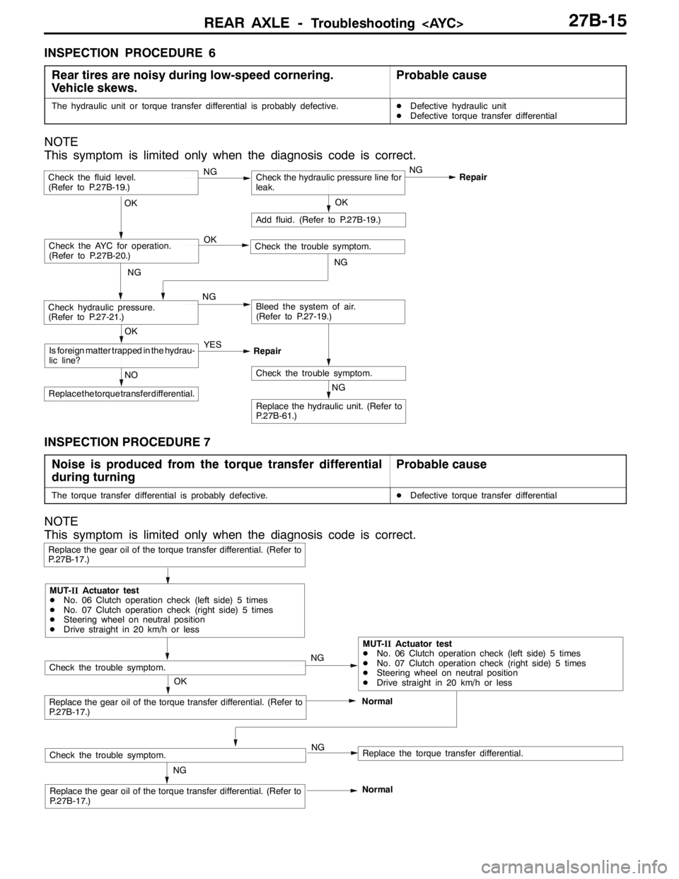
INSPECTION PROCEDURE 6
Rear tires are noisy during low-speed cornering.
Vehicle skews.
Probable cause
The hydraulic unit or torque transfer differential is probably defective.DDefective hydraulic unit
DDefective torque transfer differential
NOTE
This symptom is limited only when the diagnosis code is correct.
NG
Replace the hydraulic unit. (Refer to
P.27B-61.)
NG
Add fluid. (Refer to P.27B-19.)
OKRepair
Check the trouble symptom.NO
Replace the torque transfer differential.
OK
Is foreign matter trapped in the hydrau-
lic line?YES
Repair
Check the fluid level.
(Refer to P.27B-19.)Check the hydraulic pressure line for
leak.
OK
Check hydraulic pressure.
(Refer to P.27-21.)NGBleed the system of air.
(Refer to P.27-19.)
Check the AYC for operation.
(Refer to P.27B-20.)Check the trouble symptom. OK
NG
NGNG
INSPECTION PROCEDURE 7
Noise is produced from the torque transfer differential
during turning
Probable cause
The torque transfer differential is probably defective.DDefective torque transfer differential
NOTE
This symptom is limited only when the diagnosis code is correct.
NG
Replace the gear oil of the torque transfer differential. (Refer to
P.27B-17.)
Replace the gear oil of the torque transfer differential. (Refer to
P.27B-17.)Normal
Replace the gear oil of the torque transfer differential. (Refer to
P.27B-17.)
Replace the torque transfer differential.
Check the trouble symptom.
OKNG
NG
MUT-IIActuator test
DNo. 06 Clutch operation check (left side) 5 times
DNo. 07 Clutch operation check (right side) 5 times
DSteering wheel on neutral position
DDrive straight in 20 km/h or less
MUT-IIActuator test
DNo. 06 Clutch operation check (left side) 5 times
DNo. 07 Clutch operation check (right side) 5 times
DSteering wheel on neutral position
DDrive straight in 20 km/h or less
Check the trouble symptom.
Normal
Page 965 of 1449

REAR AXLE -On-vehicle Service27B-19
FLUID LEVEL CHECK
1. Remove the maintenance lid located in the luggage
compartment.
2.
If the vehicle has been run, leave it for 90 min. or more
in an ordinary temperature (10_C–30_C) to allow the
accumulator internal pressure to drop.
NOTE
If the ambient temperature is 10_C or less, allow more
time to leave the vehicle to stand idle.
Set MUT-IIto 16 pin diagnostic connector. Turn the ignition
switch to the ON position, operate MUT-II, drive the
hydraulic unit (item No.03) forcibly, release the pressure in
the accumulator.
Caution
Turn the ignition switch to the LOCK (OFF) position
before connecting or disconnecting the MUT-II.
NOTE
(1) To drive (oil level check mode) forcibly, turn the
directional valve of the hydraulic unit 20 turns from
side to side, release the differential automatically.
Drive can also be cleared forcibly using the Clear
key of MUT-II.
(2) If the function has been stopped by fail safe, the
hydraulic unit can not be cleared forcibly.
3. Check that the fluid level in the oil reservoir is in the
range between MAX and MIN.
4. If the fluid level is lower than MIN, add the specified
fluid.
Specified fluid: ATF-SP III
5. Reinstall the maintenance lid.
BLEEDING
1. Lift up the vehicle.
2. Set the MUT-IIto the 16-pin diagnosis connector.
Caution
Turn the ignition switch to the LOCK (OFF) position
before connecting or disconnecting the MUT-II.
3. Turn the ignition switch to the ON position.
4. Set the steering wheel in the straight-ahead position.
5. Operating the MUT-II, drive the hydraulic unit (item No.02)
forcibly.
NOTE
(1) Drive the bleeding mode forcibly for 5 minutes, release
the operation automatically. Drive can also be cleared
forcibly using the Clear key of MUT-II.
(2) If the function has been stopped by fail safe, the
hydraulic unit cannot be cleared forcibly.
Page 966 of 1449

REAR AXLE -On-vehicle Service27B-20
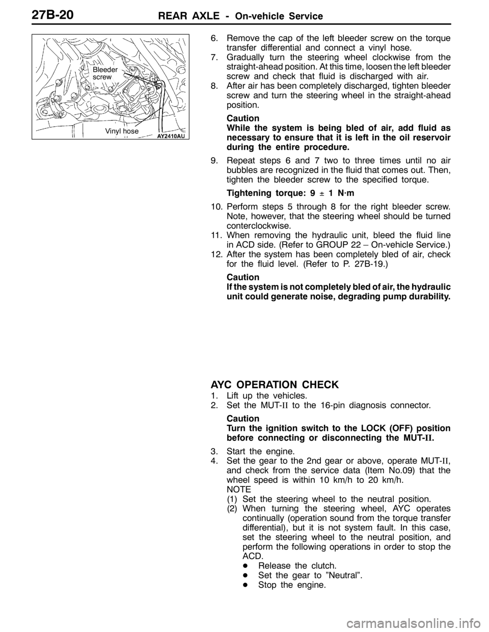
6. Remove the cap of the left bleeder screw on the torque
transfer differential and connect a vinyl hose.
7. Gradually turn the steering wheel clockwise from the
straight-ahead position. At this time, loosen the left bleeder
screw and check that fluid is discharged with air.
8. After air has been completely discharged, tighten bleeder
screw and turn the steering wheel in the straight-ahead
position.
Caution
While the system is being bled of air, add fluid as
necessary to ensure that it is left in the oil reservoir
during the entire procedure.
9. Repeat steps 6 and 7 two to three times until no air
bubbles are recognized in the fluid that comes out. Then,
tighten the bleeder screw to the specified torque.
Tightening torque: 9±1 N·m
10. Perform steps 5 through 8 for the right bleeder screw.
Note, however, that the steering wheel should be turned
conterclockwise.
11. When removing the hydraulic unit, bleed the fluid line
in ACD side. (Refer to GROUP 22 – On-vehicle Service.)
12. After the system has been completely bled of air, check
for the fluid level. (Refer to P. 27B-19.)
Caution
If the system is not completely bled of air, the hydraulic
unit could generate noise, degrading pump durability.
AYC OPERATION CHECK
1. Lift up the vehicles.
2. Set the MUT-IIto the 16-pin diagnosis connector.
Caution
Turn the ignition switch to the LOCK (OFF) position
before connecting or disconnecting the MUT-II.
3. Start the engine.
4. Set the gear to the 2nd gear or above, operate MUT-II,
and check from the service data (Item No.09) that the
wheel speed is within 10 km/h to 20 km/h.
NOTE
(1) Set the steering wheel to the neutral position.
(2) When turning the steering wheel, AYC operates
continually (operation sound from the torque transfer
differential), but it is not system fault. In this case,
set the steering wheel to the neutral position, and
perform the following operations in order to stop the
ACD.
DRelease the clutch.
DSet the gear to ”Neutral”.
DStop the engine.
Bleeder
screw
Vinyl hose
Page 1012 of 1449

WHEEL AND TYRE -Troubleshooting31-4
WHEEL BALANCE ACCURACY
PURPOSE
This section contains tips and procedures for
achieving accurate wheel balance. Steering wheel
vibration and /or body shake can result if any of
these procedures are not carefully observed.
1. Wheels and tires must be properly mounted
on a balancer in order to achieve correct
balance. Centering the wheel on the shaft of
the balancer is essential for proper mounting.
2. Off-the-car wheel balancers must be calibrated
periodically to ensure good balancing results.
An inaccurately calibrated balancer could cause
unnecessary replacement of tires, shocks,
suspension components, or steering
components.Check your balancer’s calibration approximately
every 100 balances. Your wheel balancer’s
instruction manual should include calibration
procedures. If the calibration procedures
specifically for your balancer are missing, use the
generic steps in this section for zero calibration,
static balance, and dynamic balance checks. The
wheel balancer calibration checks are also
described in the flowchart. (Refer to P.31-5.)
PROCEDURE
Balancing Tips
1. Confirm that the balancer’s cone and the wheel
mounting cone are undamaged and free of
dirt and rust.
2. On this vehicle the wheel’s center hole on the
hub side has a chamfered edge. Use a
back-mounting cone on your wheel balancer
to center the wheel on the balancer shaft.3. Install a wheel mounting cone. The appropriate
size cone for this vehicle is 67.0 mm.
4. Before balancing the wheel, remove any wheel
weights from both sides. Also check both sides
for any damage.
5. When installing wheel weights, hammer them
at a straight (not diagonal) angle.
Hub/shaft assembly
Spring plateClamping cup
Wheel mounting
cone
Standard passenger
car wheelWing nut
Confirming Proper Balance
1. After balancing the wheel, loosen the wing nut
and turn the wheel 180°against the balancer’s
hub. Then retighten the wing nut and check
the balance again. Repeat wheel balance if
necessary.2. Turn the wheel again 180°against the
balancer’s hub. If the wheel becomes
out-of-balance each time it is turned against
the balancer’s hub, the wheel balancer may
require calibration.
Wheel Balancer Calibration Checks
1. Mount an undamaged original-equipment alloy
rim and tire assembly (wheel) onto your
off-the-car wheel balancer. Balance the wheel.2.<
Loosen the balancer wing nut, rotate the wheel
a half turn (180°), and retighten the nut.
Recheck the balance.
Page 1022 of 1449

POWER PLANT MOUNT - Crossmember32-8
CROSSMEMBER
REMOVAL AND INSTALLATION
Caution
1. Before removing the steering wheel and air bag module assembly, always refer to GROUP
52B - Service Precautions, Air bag Module and Clock Spring. Also, set the front wheels so
that they are facing straight forward, and remove the ignition key. If you fail to do this, the
SRS clock spring will be damaged, causing the SRS air bag to be inoperative and serious
injury.
2. *
1: Indicates parts which should be initially tightened, and then fully tightened after placing
the vehicle horizontally and loading the full weight of the engine on the vehicle body.
3. *
2: Indicates parts which should be temporarily tightened, and then fully tightened with the
vehicle on the ground in the unladen condition.
Caution
If the vehicle is equipped the Brembo disc brake, during maintenance, take care not to contact
the parts or tools to the caliper because the paint of caliper will be scratched.
Pre-removal Operations
DUnder Cover Removal
(Refer to GROUP 51 - Front Bumper.)
DCentermember, Crossmember Bar Removal
(Refer to P.32-6.)
DFront Exhaust Pipe Removal
(Refer to GROUP 15.)
DSteering Wheel Air Bag Module Assembly Removal
(Refer to GROUP 37A.)
DPower Steering Fluid Draining
(Refer to GROUP 37A - On-vehicle Service.)Post-installation Operations
DCentermember, Crossmember Bar Installation
(Refer to P.32-6.)
DFront Exhaust Pipe Installation
(Refer to GROUP 15.)
DSteering Wheel Air Bag Module Assembly
Installation (Refer to GROUP 37A.)
DPower Steering Fluid Supplying
(Refer to GROUP 37A - On-vehicle Service.)
DPower Steering Fluid Line Bleeding
(Refer to GROUP 37A - On-vehicle Service.)
DPress the dust cover with a finger to check whether
the dust cover is cracked or damaged.
DChecking Steering Wheel Position with Wheels
Straight Ahead
DFront Wheel Alignment Check and Adjustment
(Refer to GROUP 37A - On-vehicle Service.)
DUnder Cover Installation
(Refer to GROUP 51 - Front Bumper.)
Page 1029 of 1449

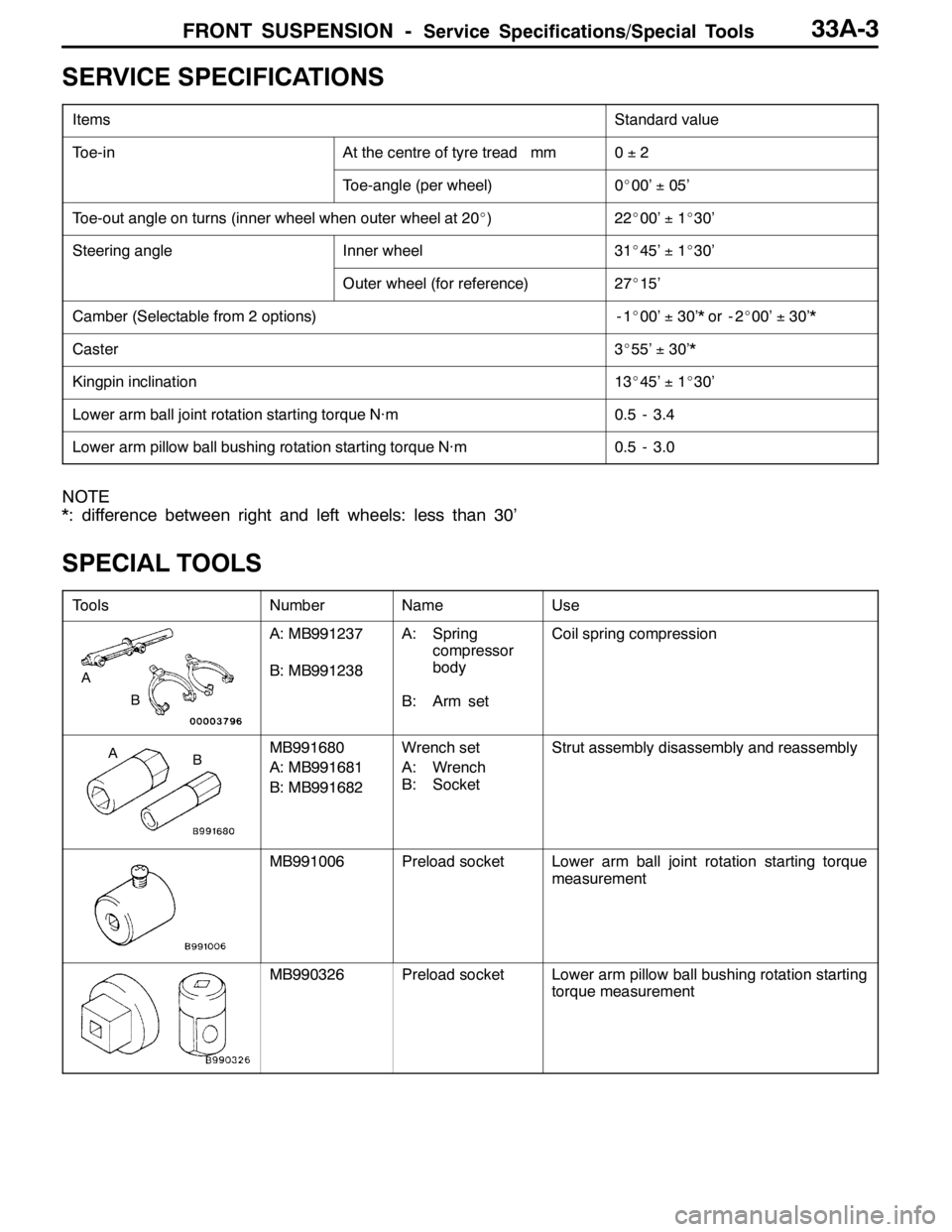
FRONT SUSPENSION -Service Specifications/Special Tools33A-3
SERVICE SPECIFICATIONS
ItemsStandard value
Toe-inAt the centre of tyre tread mm0±2
Toe-angle (per wheel)0_00’±05’
Toe-out angle on turns (inner wheel when outer wheel at 20_)22_00’±1_30’
Steering angleInner wheel31_45’±1_30’
Outer wheel (for reference)27_15’
Camber (Selectable from 2 options)-1_00’±30’* or - 2_00’±30’*
Caster3_55’±30’*
Kingpin inclination13_45’±1_30’
Lower arm ball joint rotation starting torque N·m0.5 - 3.4
Lower arm pillow ball bushing rotation starting torque N·m0.5 - 3.0
NOTE
*: difference between right and left wheels: less than 30’
SPECIAL TOOLS
ToolsNumberNameUse
B
A
A: MB991237
B: MB991238A: Spring
compressor
body
B: Arm setCoil spring compression
BAMB991680
A: MB991681
B: MB991682Wrench set
A: Wrench
B: SocketStrut assembly disassembly and reassembly
MB991006Preload socketLower arm ball joint rotation starting torque
measurement
MB990326Preload socketLower arm pillow ball bushing rotation starting
torque measurement
Page 1030 of 1449

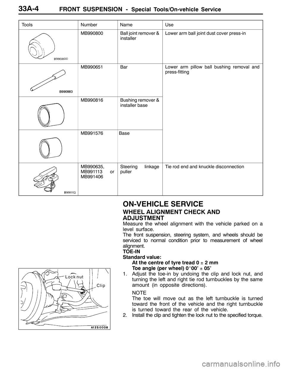
FRONT SUSPENSION -Special Tools/On-vehicle Service33A-4
Tools UseName Number
MB990800Ball joint remover &
installerLower arm ball joint dust cover press-in
MB990651BarLower arm pillow ball bushing removal and
press-fitting
MB990816Bushing remover &
installer base
MB991576Base
MB990635,
MB991113 or
MB991406Steering linkage
pullerTie rod end and knuckle disconnection
ON-VEHICLE SERVICE
WHEEL ALIGNMENT CHECK AND
ADJUSTMENT
Measure the wheel alignment with the vehicle parked on a
level surface.
The front suspension, steering system, and wheels should be
serviced to normal condition prior to measurement of wheel
alignment.
TOE-IN
Standard value:
At the centre of tyre tread 0±2mm
Toe angle (per wheel) 0_00’±05’
1. Adjust the toe-in by undoing the clip and lock nut, and
turning the left and right tie rod turnbuckles by the same
amount (in opposite directions).
NOTE
The toe will move out as the left turnbuckle is turned
toward the front of the vehicle and the right turnbuckle
is turned toward the rear of the vehicle.
2. Install the clip and tighten the lock nut to the specified torque.
Clip
Lock nut