Page 1001 of 1449

REAR AXLE -Differential Carrier 27B-55
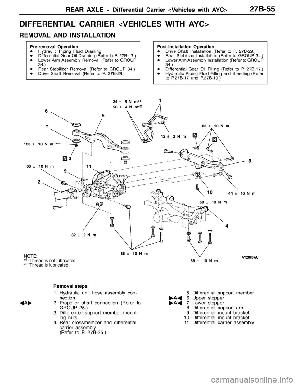
DIFFERENTIAL CARRIER
REMOVAL AND INSTALLATION
Pre-removal Operation
DHydraulic Piping Fluid Draining
DDifferential Gear Oil Draining (Refer to P. 27B-17.)
DLower Arm Assembly Removal (Refer to GROUP
34.)
DRear Stabilizer Removal (Refer to GROUP 34.)
DDrive Shaft Removal (Refer to P. 27B-29.)Post-installation Operation
DDrive Shaft Installation (Refer to P. 27B-29.)
DRear Stabilizer Installation (Refer to GROUP 34.)
DLower Arm Assembly Installation (Refer to GROUP
34.)
DDifferential Gear Oil Filling (Refer to P. 27B-17.)
DHydraulic Piping Fluid Filling and Bleeding (Refer
to P.27B-17 and P.27B-19.)
1
2
88�¶10 N��m
7 6
5
48
9
10 3
11
44�¶10 N��m
120�¶10 N��m34�¶5N��m*
1
32�¶2N��m
12�¶2N��m 26�¶4N��m*
2
88�¶10 N��m
88�¶10 N��m 88�¶10 N��m 88�¶10 N��mNOTE:
*1:Thread is not lubricated
*2:Thread is lubricated
Removal steps
1. Hydraulic unit hose assembly con-
nection
AA"2. Propeller shaft connection (Refer to
GROUP 25.)
3. Differential support member mount-
ing nuts
4. Rear crossmember and differential
carrier assembly
(Refer to P. 27B-35.)5. Differential support member
"AA6. Upper stopper
"AA7. Lower stopper
8. Differential support arm
9. Differential mount bracket
10. Differential mount bracket
11. Differential carrier assembly
Page 1004 of 1449
REAR AXLE -Differential Carrier 27B-58
TORQUE TRANSFER DIFFERENTIAL
DISASSEMBLY AND REASSEMBLY
Caution
1. The differential carrier assembly is non-maintainable.
2. No foreign matter should be allowed inside and at the joints of the differential carrier assembly.
14
2
6
4
35
7
1
9
10
8
3
4
11
13
12
186�¶29 N��m
32�¶2N��m 49�¶10 N��m
5�¶1N��m
9�¶1N��m 49�¶10 N��m
Disassembly steps
1. Drain plug
2. Packing
3. Filler plug
4. Gasket
5. Vent plug
6. Bleeder screw
7. CoverAA"8. Self-locking nut
9. Washer
10. Companion flange
11. Oil seal
"BA12. Oil seal
"AA13. Oil seal
14. Differential carrier assembly
Page 1007 of 1449

REAR AXLE- Hydraulic Unit 27B-61
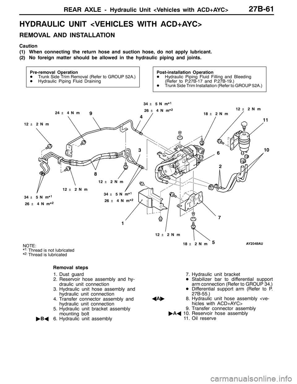
HYDRAULIC UNIT
REMOVAL AND INSTALLATION
Caution
(1) When connecting the return hose and suction hose, do not apply lubricant.
(2) No foreign matter should be allowed in the hydraulic piping and joints.
Pre-removal Operation
DTrunk Side Trim Removal (Refer to GROUP 52A.)
DHydraulic Piping Fluid DrainingPost-installation Operation
DHydraulic Piping Fluid Filling and Bleeding
(Refer to P.27B-17 and P.27B-19.)
DTrunk Side Trim Installation (Refer to GROUP 52A.)
12
7 6 4
8 9
10
311
34�¶5N��m*1
24�¶4N��m
12�¶2N��m
26�¶4N��m*
2
5
12�¶2N��m
12�¶2N��m
18�¶2N��m 34�¶5N��m*1
26�¶4N��m*2
18�¶2N��m12�¶2N��m 34�¶5N��m*
1
26�¶4N��m*2
12�¶2N��m
NOTE:
*1:Thread is not lubricated
*2:Thread is lubricated
Removal steps
1. Dust guard
2. Reservoir hose assembly and hy-
draulic unit connection
3. Hydraulic unit hose assembly and
hydraulic unit connection
4. Transfer connector assembly and
hydraulic unit connection
5. Hydraulic unit bracket assembly
mounting bolt
"BA6. Hydraulic unit assembly7. Hydraulic unit bracket
DStabilizer bar to differential support
arm connection (Refer to GROUP 34.)
DDifferential support arm (Refer to P.
27B-55.)
AA"8. Hydraulic unit hose assembly
hicles with ACD+AYC>
9. Transfer connector assembly
"AA10. Reservoir hose assembly
11. Oil reserve
Page 1022 of 1449

POWER PLANT MOUNT - Crossmember32-8
CROSSMEMBER
REMOVAL AND INSTALLATION
Caution
1. Before removing the steering wheel and air bag module assembly, always refer to GROUP
52B - Service Precautions, Air bag Module and Clock Spring. Also, set the front wheels so
that they are facing straight forward, and remove the ignition key. If you fail to do this, the
SRS clock spring will be damaged, causing the SRS air bag to be inoperative and serious
injury.
2. *
1: Indicates parts which should be initially tightened, and then fully tightened after placing
the vehicle horizontally and loading the full weight of the engine on the vehicle body.
3. *
2: Indicates parts which should be temporarily tightened, and then fully tightened with the
vehicle on the ground in the unladen condition.
Caution
If the vehicle is equipped the Brembo disc brake, during maintenance, take care not to contact
the parts or tools to the caliper because the paint of caliper will be scratched.
Pre-removal Operations
DUnder Cover Removal
(Refer to GROUP 51 - Front Bumper.)
DCentermember, Crossmember Bar Removal
(Refer to P.32-6.)
DFront Exhaust Pipe Removal
(Refer to GROUP 15.)
DSteering Wheel Air Bag Module Assembly Removal
(Refer to GROUP 37A.)
DPower Steering Fluid Draining
(Refer to GROUP 37A - On-vehicle Service.)Post-installation Operations
DCentermember, Crossmember Bar Installation
(Refer to P.32-6.)
DFront Exhaust Pipe Installation
(Refer to GROUP 15.)
DSteering Wheel Air Bag Module Assembly
Installation (Refer to GROUP 37A.)
DPower Steering Fluid Supplying
(Refer to GROUP 37A - On-vehicle Service.)
DPower Steering Fluid Line Bleeding
(Refer to GROUP 37A - On-vehicle Service.)
DPress the dust cover with a finger to check whether
the dust cover is cracked or damaged.
DChecking Steering Wheel Position with Wheels
Straight Ahead
DFront Wheel Alignment Check and Adjustment
(Refer to GROUP 37A - On-vehicle Service.)
DUnder Cover Installation
(Refer to GROUP 51 - Front Bumper.)
Page 1059 of 1449

BASIC BRAKE SYSTEM -Brake Pedal/Proportioning Valve,
Master Cylinder and Brake Booster35A-17
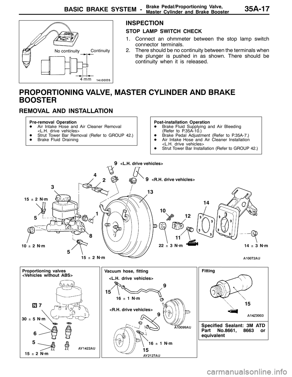
INSPECTION
STOP LAMP SWITCH CHECK
1. Connect an ohmmeter between the stop lamp switch
connector terminals.
2. There should be no continuity between the terminals when
the plunger is pushed in as shown. There should be
continuity when it is released.
PROPORTIONING VALVE, MASTER CYLINDER AND BRAKE
BOOSTER
REMOVAL AND INSTALLATION
Pre-removal Operation
DAir Intake Hose and Air Cleaner Removal
DStrut Tower Bar Removal (Refer to GROUP 42.)
DBrake Fluid DrainingPost-installation Operation
DBrake Fluid Supplying and Air Bleeding
(Refer to P.35A-10.)
DBrake Pedal Adjustment (Refer to P.35A-7.)
DAir Intake Hose and Air Cleaner Installation
DStrut Tower Bar Installation (Refer to GROUP 42.)
510
11 3
12 4
14
15±2N·m 15±2N·m
22±3N·m
10±2N·m
13 2
8
14±3N·m
519
9
15±2N·m
5
Proportioning valves
67
30±5N·m
9
15
16±1N·m
9
15
16±1N·m
Vacuum hose, fitting
Specified Sealant: 3M ATD
Part No.8661, 8663 or
equivalent
15
Fitting
4mm
No continuityContinuity
Page 1062 of 1449
BASIC BRAKE SYSTEM -Disc Brake35A-20
DISC BRAKE
REMOVAL AND INSTALLATION
Caution
If the vehicle is equipped with the Brembo disc brake, during maintenance, take care not to contact
the parts or tools to the caliper because the paint of caliper will be scratched. And if there is
brake fluid on the caliper, wipe out quickly.
Pre-removal Operation
Brake Fluid DrainingPost-installation Operation
Brake Fluid Supplying and Air Bleeding
(Refer to P.35A-10.)
34
21
100±10 N·m
108±10 N·m
30±5 N·m
3 2 1
54±5 N·m
15±2 N·m
4
Removal steps
1. Brake hose connection
2. Gasket
"AA3. Disc brake assembly
4. Brake disc
Page 1100 of 1449
ABS <4WD> -Hydraulic Unit and ABS-ECU35B-30
HYDRAULIC UNIT AND ABS-ECU
REMOVAL AND INSTALLATION
Pre-removal Operation
DStrut Tower Bar Removal (Refer to GROUP 42.)
DBrake Fluid DrainingPost-installation Operation
DBrake Fluid Supplying and Brake Line Bleeding
(Refer to GROUP 35A - On-vehicle Service.)
DHydraulic Unit Check (Refer to P.35B-28.)
DStrut Tower Bar Installation (Refer to GROUP 42.)
23
42
2
2
15±2 N·m
25±6 N·m
1
25±6 N·m
Removal steps
AA"1. Harness connector
"AA2. Brake pipe connectionAB"3. Hydraulic unit and ABS-ECU
4. Hydraulic unit bracket assembly
Page 1101 of 1449
ABS <4WD> -Hydraulic Unit and ABS-ECU35B-31
Pre-removal Operation
DStrut Tower Bar Removal (Refer to GROUP 42.)
DBrake Fluid Draining
DAir Intake Hose and Air Cleaner RemovalPost-installation Operation
DBrake Fluid Supplying and Brake Line Bleeding
(Refer to GROUP 35A - On-vehicle Service.)
DHydraulic Unit Check (Refer to P.35B-28.)
DAir Intake Hose and Air Cleaner Installation
DStrut Tower Bar Installation (Refer to GROUP 42.)
213
4 2
2
2
15±2 N·m
25±6 N·m
25±6 N·m
Removal steps
AA"1. Harness connector
"AA2. Brake pipe connectionAB"3. Hydraulic unit and ABS-ECU
4. Hydraulic unit bracket assembly