Page 702 of 1449
ENGINE COOLING -Water Hose and Water Pipe14-14
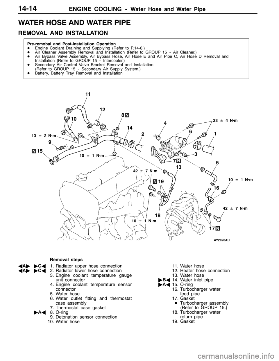
WATER HOSE AND WATER PIPE
REMOVAL AND INSTALLATION
Pre-remobal and Post-installation Operation
DEngine Coolant Draining and Supplying (Refer to P.14-6.)
DAir Cleaner Assembly Removal and Installation (Refer to GROUP 15 - Air Cleaner.)
DAir Bypass Valve Assembly, Air Bypass Hose, Air Hose E and Air Pipe C, Air Hose D Removal and
Installation (Refer to GROUP 15 - Intercooler.)
DSecondary Air Control Valve Bracket Removal and Installation
(Refer to GROUP 15 - Secondary Air Supply System.)
DBattery, Battery Tray Removal and Installation
3 4
5 6
7 8
9
1012
10±1 N·m
42±7 N·m 13±2 N·m
11
1
2
23±4 N·m
18
1716 1514
13
19
10±1 N·m
42±7 N·m
10±1 N·m
Removal steps
AA""CA1. Radiator upper hose connection
AA""CA2. Radiator lower hose connection
3. Engine coolant temperature gauge
unit connector
4. Engine coolant temperature sensor
connector
5. Water hose
6. Water outlet fitting and thermostat
case assembly
7. Thermostat case gasket
"AA8. O-ring
9. Detonation sensor connection
10. Water hose11. Water hose
12. Heater hose connection
13. Water hose
"BA14. Water inlet pipe
"AA15. O-ring
16. Turbocharger water
feed pipe
17. Gasket
DTurbocharger assembly
(Refer to GROUP 15.)
18. Turbocharger water
return pipe
19. Gasket
Page 703 of 1449
ENGINE COOLING -Water Hose and Water Pipe/Radiator14-15
REMOVAL SERVICE POINT
AA"RADIATOR UPPER HOSE/RADIATOR LOWER
HOSE DISCONNECTION
After making mating marks on the hose and the hose clamp,
disconnect the hose.
INSTALLATION SERVICE POINTS
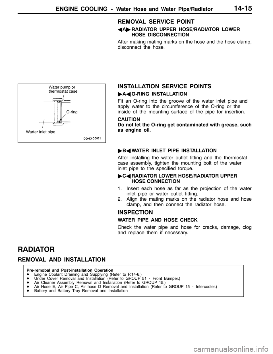
"AAO-RING INSTALLATION
Fit an O-ring into the groove of the water inlet pipe and
apply water to the circumference of the O-ring or the
inside of the mounting surface of the pipe for insertion.
CAUTION
Do not let the O-ring get contaminated with grease, such
as engine oil.
"BAWATER INLET PIPE INSTALLATION
After installing the water outlet fitting and the thermostat
case assembly, tighten the mounting bolt of the water
inlet pipe to the specified torque.
"CARADIATOR LOWER HOSE/RADIATOR UPPER
HOSE CONNECTION
1. Insert each hose as far as the projection of the water
inlet pipe or water outlet fitting.
2. Align the mating marks on the radiator hose and hose
clamp, and then connect the radiator hose.
INSPECTION
WATER PIPE AND HOSE CHECK
Check the water pipe and hose for cracks, damage, clog
and replace them if necessary.
RADIATOR
REMOVAL AND INSTALLATION
Pre-remobal and Post-installation Operation
DEngine Coolant Draining and Supplying (Refer to P.14-6.)
DUnder Cover Removal and Installation (Refer to GROUP 51 - Front Bumper.)
DAir Cleaner Assembly Removal and Installation (Refer to GROUP 15.)
DAir Hose E, Air Pipe C, Air hose D Removal and Installation (Refer to GROUP 15 - Intercooler.)
DBattery and Battery Tray Removal and Installation
Water pump or
thermostat case
O-ring
Warter inlet pipe
Page 704 of 1449
ENGINE COOLING -Radiator14-16
1 23
45
6
7
12±2 N·m
9
16
14 19
18 12
17 10
8
13
15 10
20 21
12±2 N·m5.0±1.0 N·m
3.5±0.4 N·m
4.5±0.4 N·m4.0±0.4 N·m
13
1112±1 N·m
Radiator removal steps
1. Radiator drain plug
2. Radiator cap
3. Reserve tank hose
4. Reserve tank
5. Reserve tank cap
6. Reserve tank hose
7. Reserve tank bracket
AA""AA8. Radiator upper hose
AA""AA9. Radiator lower hose
10. Upper insulator
AB"11. Air Pipe B mounting bolt
12. Radiator assembly
13. Lower insulator
14. Radiator fan controller connector
15. Radiator fan controller, radiator fan
motor, fan and shroud assemblyRadiator fun controller and radiator
fun motor removal steps
AB"11. Air Pipe B mounting bolt
14. Radiator fan controller connector
16. Radiator fan motor connector
17. Radiator fan controller
18. Radiator fan motor fan and shroud
assembly
19. Fan
20. Radiator fan motor
21. Shroud
Page 722 of 1449
INTAKE AND EXHAUST -Intake Manifold15-16
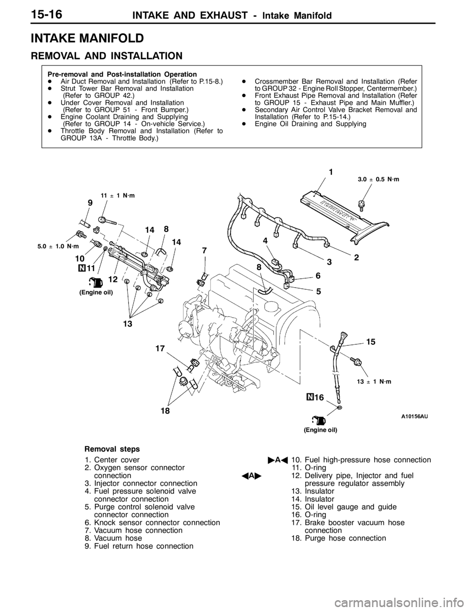
INTAKE MANIFOLD
REMOVAL AND INSTALLATION
Pre-removal and Post-installation Operation
DAir Duct Removal and Installation (Refer to P.15-8.)
DStrut Tower Bar Removal and Installation
(Refer to GROUP 42.)
DUnder Cover Removal and Installation
(Refer to GROUP 51 - Front Bumper.)
DEngine Coolant Draining and Supplying
(Refer to GROUP 14 - On-vehicle Service.)
DThrottle Body Removal and Installation (Refer to
GROUP 13A - Throttle Body.)DCrossmember Bar Removal and Installation (Refer
to GROUP 32 - Engine Roll Stopper, Centermember.)
DFront Exhaust Pipe Removal and Installation (Refer
to GROUP 15 - Exhaust Pipe and Main Muffler.)
DSecondary Air Control Valve Bracket Removal and
Installation (Refer to P.15-14.)
DEngine Oil Draining and Supplying
1
2
3 4
5 6 7
8 10
11
1214
13
15
16 17
18
9
11±1 N·m3.0±0.5 N·m
13±1 N·m
(Engine oil)
(Engine oil) 5.0±1.0 N·m
14 8
Removal steps
1. Center cover
2. Oxygen sensor connector
connection
3. Injector connector connection
4. Fuel pressure solenoid valve
connector connection
5. Purge control solenoid valve
connector connection
6. Knock sensor connector connection
7. Vacuum hose connection
8. Vacuum hose
9. Fuel return hose connection"AA10. Fuel high-pressure hose connection
11. O-ring
AA"12. Delivery pipe, Injector and fuel
pressure regulator assembly
13. Insulator
14. Insulator
15. Oil level gauge and guide
16. O-ring
17. Brake booster vacuum hose
connection
18. Purge hose connection
Page 797 of 1449
CLUTCH -Clutch Control21A-7
CLUTCH CONTROL
REMOVAL AND INSTALLATION
Pre-removal Operation
Clutch Fluid DrainingPost-installation Operation
DClutch Fluid Supplying
DClutch Pedal Adjustment (Refer to P.21A-3.)
DClutch Pedal Position Switch Adjustment (Refer to
P.21A-4.)
DClutch Line Bleeding (Refer to P.21A-4.)
7
6
114
95 21
3 10
15±1 N·m
30±4 N·m
13±2 N·m
12±2 N·m
18±3 N·m
10
8
Specified grease:
MITSUBISHI genuine grease
Part No. 0101011
Release cylinder
push rodRelease fork
11
Clutch master cylinder removal
steps
1. Clevis pin assembly
2. Eye bolt
3. Gasket
4. Reservoir hose
5. Clevis pin and pushrod assembly con-
necting part
6. Clutch master cylinder
7. Sealer
8. Retainer assemblyClutch release cylinder removal
steps
10. Clutch pipe
11. Clutch release cylinder
Clutch line removal steps
9. Clutch hose
10. Clutch pipe
Page 848 of 1449
MANUAL TRANSMISSION - On-vehicle Service MANUAL TRANSMISSION - On-vehicle Service22A-40
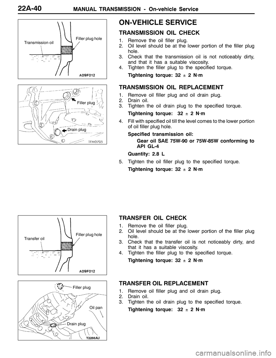
ON-VEHICLE SERVICE
TRANSMISSION OIL CHECK
1. Remove the oil filler plug.
2. Oil level should be at the lower portion of the filler plug
hole.
3. Check that the transmission oil is not noticeably dirty,
and that it has a suitable viscosity.
4. Tighten the filler plug to the specified torque.
Tightening torque: 32±2 N·m
TRANSMISSION OIL REPLACEMENT
1. Remove oil filler plug and oil drain plug.
2. Drain oil.
3. Tighten the oil drain plug to the specified torque.
Tightening torque: 32±2 N·m
4. Fill with specified oil till the level comes to the lower portion
of oil filler plug hole.
Specified transmission oil:
Gear oil SAE 75W-90 or 75W-85W conforming to
API GL-4
Quantity: 2.8 L
5. Tighten the oil filler plug to the specified torque.
Tightening torque: 32±2 N·m
TRANSFER OIL CHECK
1. Remove the oil filler plug.
2. Oil level should be at the lower portion of the filler plug
hole.
3. Check that the transfer oil is not noticeably dirty, and
that it has a suitable viscosity.
4. Tighten the filler plug to the specified torque.
Tightening torque: 32±2 N·m
TRANSFER OIL REPLACEMENT
1. Remove oil filler plug and oil drain plug.
2. Drain oil.
3. Tighten the oil drain plug to the specified torque.
Tightening torque: 32±2 N·m
Transmission oilFiller plug hole
Filler plug
Drain plug
Transfer oilFiller plug hole
Filler plug
Drain plug
Oil pan
Page 857 of 1449
MANUAL TRANSMISSION - Transfer Assembly22A-49
TRANSFER ASSEMBLY
REMOVAL AND INSTALLATION
Pre-removal and Post-installation Operation
DUnder Cover Removal and Installation (Refer to GROUP 51 - Front Bumper.)
DSide Under Cover Removal and Installation
DTransmission Oil Draining and Supplying (Refer to P.22A-40.)
DTransfer Oil Draining and Supplying (Refer to P.22A-40.)
DEngine Coolant Draining and Supplying (Refer to GROUP 14 - On-vehicle Service.)
DCrossmember Bar Removal and Installation (Refer to GROUP 32 - Engine Roll Stopper, Centermember.)
DFront Exhaust Pipe Removal and Installation (Refer to GROUP 15 - Exhaust Pipe and Main Muffler.)
DBattery and Battery Tray Removal and Installation
DAir Cleaner, Air Intake Hose Removal and Installation (Refer to GROUP 15 - Air Cleaner.)
DSecondary Air Hose Removal and Installation (Refer to GROUP 15 - Secondary Air Control System.)
DStrut Tower Bar Removal and Installation (Refer to GROUP 42.)
DAir Hose E, Air By-pass Hose and Air By-pass Valve, Air Pipe C, Air Hose D, Air Pipe B, Air Hose A Removal and
Installation (Refer to GROUP 15 - Intercooler.)
DRadiator Removal and Installation (Refer to GROUP 14.)
DBleeding and Hydraulic Pressure Check (Refer to P.22A-42, 43)
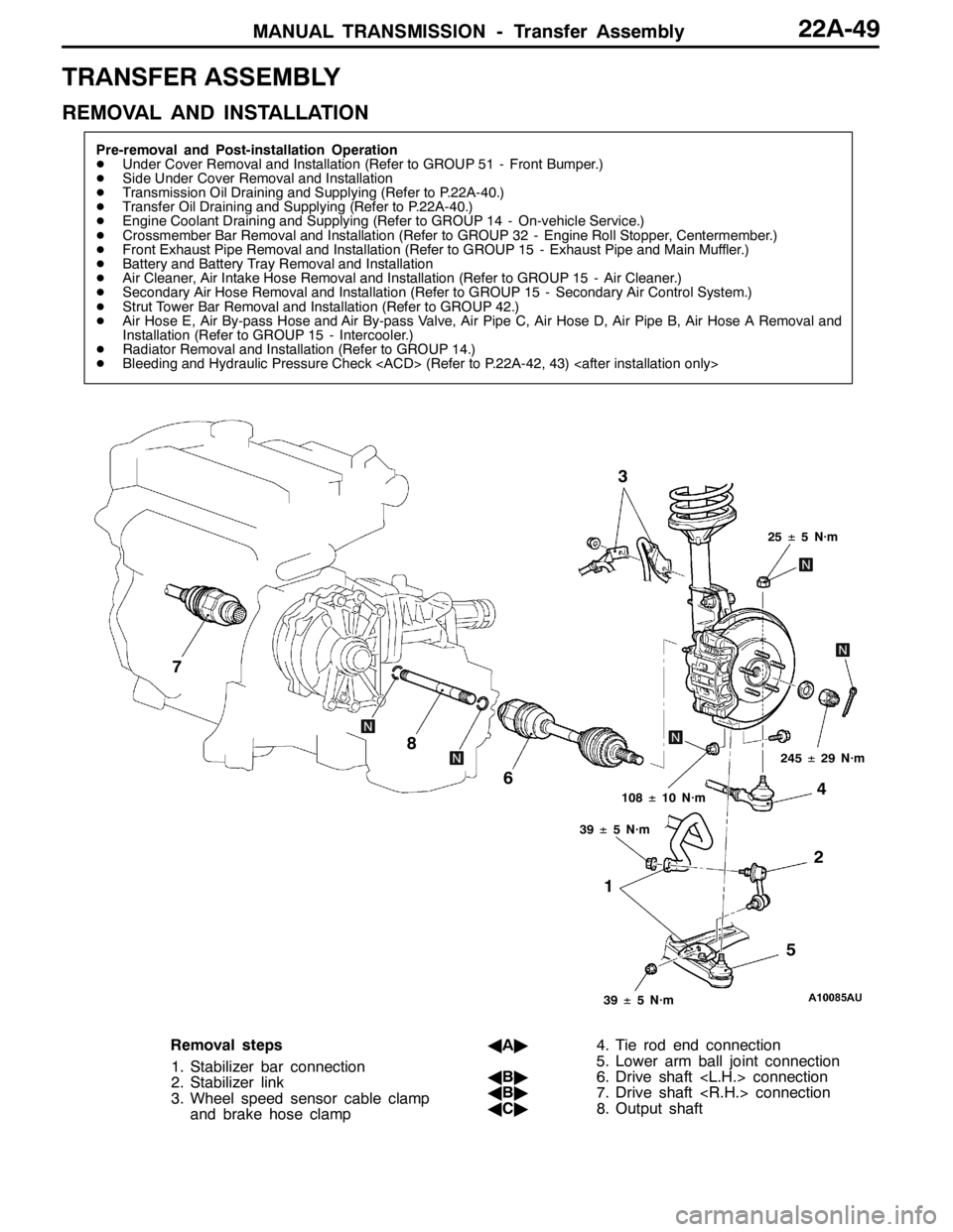
12 3
4
5 6 7
8
25±5 N·m
108±10 N·m
39±5 N·m
39±5 N·m
245±29 N·m
Removal steps
1. Stabilizer bar connection
2. Stabilizer link
3. Wheel speed sensor cable clamp
and brake hose clampAA"4. Tie rod end connection
5. Lower arm ball joint connection
AB"6. Drive shaft connection
AB"7. Drive shaft connection
AC"8. Output shaft
Page 934 of 1449
FRONT AXLE -Hub and Knuckle Assembly26-6
HUB AND KNUCKLE ASSEMBLY
REMOVAL AND INSTALLATION
Caution
If the vehicle is equipped with the Brembo disc brake, during maintenance, take care not to
contact the parts or tools to the caliper because the paint of caliper will be scratched. And if
there is brake fluid on the caliper, wipe out quickly.
Pre-removal and Post-installation Operation
DTransmission Fluid Draining
DTransfer Oil Draining (Refer to GROUP 22 –
On-vehicle Service.)Pre-removal and Post-installation Operation
DCheck the dust cover for cracks or damage by
pushing it with finger.
DTransfer Oil Filling (Refer to GROUP 22 –
On-vehicle Service.)
DTransmission Fluid Filling
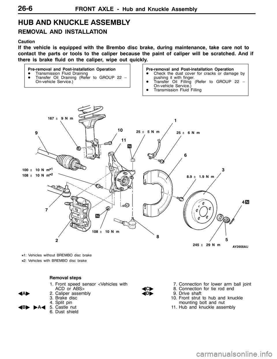
25�¶5N��m
1
245�¶29 N��m
58
3
4
2
108�¶10 N��m
10
11
25�¶6N��m
6
9
100�¶10 N��m*1
108�¶10 N��m*2
167�¶9N��m
8.9�¶1.9 N��m
*1: Vehicles without BREMBO disc brake
*2: Vehicles with BREMBO disc brake
7
Removal steps
1. Front speed sensor
ACD or ABS>
AA"2. Caliper assembly
3. Brake disc
4. Split pin
AB""AA5. Castle nut
6. Dust shield7. Connection for lower arm ball joint
AC"8. Connection for tie rod end
AD"9. Drive shaft
10. Front strut to hub and knuckle
mounting bolt and nut
11. Hub and knuckle assembly