Page 431 of 1449

ENGINE -Oil Pan11A-25
INSTALLATION SERVICE POINTS
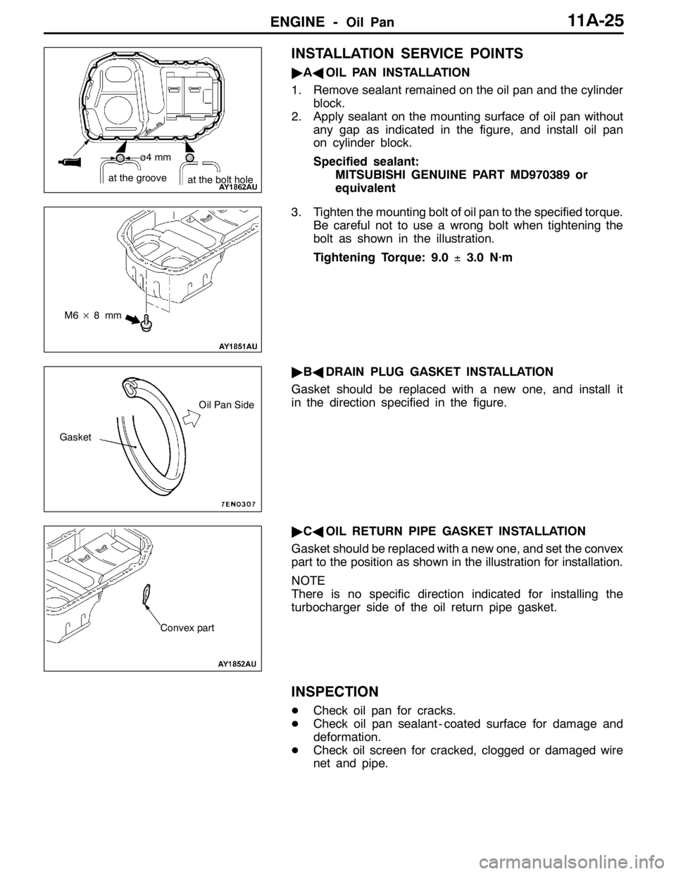
"AAOIL PAN INSTALLATION
1. Remove sealant remained on the oil pan and the cylinder
block.
2. Apply sealant on the mounting surface of oil pan without
any gap as indicated in the figure, and install oil pan
on cylinder block.
Specified sealant:
MITSUBISHI GENUINE PART MD970389 or
equivalent
3. Tighten the mounting bolt of oil pan to the specified torque.
Be careful not to use a wrong bolt when tightening the
bolt as shown in the illustration.
Tightening Torque: 9.0±3.0 N·m
"BADRAIN PLUG GASKET INSTALLATION
Gasket should be replaced with a new one, and install it
in the direction specified in the figure.
"CAOIL RETURN PIPE GASKET INSTALLATION
Gasket should be replaced with a new one, and set the convex
part to the position as shown in the illustration for installation.
NOTE
There is no specific direction indicated for installing the
turbocharger side of the oil return pipe gasket.
INSPECTION
DCheck oil pan for cracks.
DCheck oil pan sealant - coated surface for damage and
deformation.
DCheck oil screen for cracked, clogged or damaged wire
net and pipe.
ø4 mm
at the groove
at the bolt hole
M6×8mm
Gasket
Oil Pan Side
Convex part
Page 434 of 1449

ENGINE -Cylinder Head Gasket11A-28
CYLINDER HEAD GASKET
REMOVAL AND INSTALLATION
Caution
If the vehicle is equipped with the Brembo disc brake, during maintenance, take care not to contact
the parts or tools to the caliper because the paint of caliper will be scratched.
Pre-removal and Post-installation Operation
DFuel Outflow Preventive Operation (Refer to GROUP 13A - On-vehicle Service.)
DFuel Leak Check
DStrut Tower Bar Removal and Installation (Refer to GROUP 42.)
DUnder Cover Removal and Installation (Refer to GROUP 51 - Front Bumper.)
DDrive Belt Tension Check (Refer to P.11A-7.)
DAccelerator Cable Adjustment (Refer to GROUP 17 - On-vehicle Service.)
DDrainage and Refilling Engine Oil (Refer to GROUP 12 - On-vehicle Service.)
DDrainage and Refilling of Engine Coolant (Refer to GROUP 14 - On-vehicle Service.)
DAir Cleaner Assembly Removal and Installation (Refer to GROUP 15.)
DAir Hose E, Air Pipe C, Air hose D Removal and Installation (Refer to GROUP 15 - Intercooler.)
DBattery Removal and Installation
DCenter Cover Removal and Installation (Refer to P.11A-17.)
DAccelerator Cable Removal and Installation (Refer to GROUP 17.)
DRadiator Removal and Installation (Refer to GROUP 14.)
DSecondary Air Control Valve Bracket Removal and Installation (Refer to GROUP 15 - Secondary Air Supply System.)
DCrossmember Bar Removal and Installation (Refer to GROUP32 - Engine Roll Stopper, Centermember.)
DFront Exhaust Pipe Removal and Installation (Refer to GROUP 15.)
DStarter Removal and Installation (Refer to GROUP 16.)
DTiming Belt Removal and Installation (Refer to P.11A-34.)
Page 449 of 1449

ENGINE -Engine Assembly11A-43
ENGINE ASSEMBLY
REMOVAL AND INSTALLATION
Caution
1. If the vehicle is equipped with the Brembo disc brake, during maintenance, take care not to
contact the parts or tools to the caliper because the paint of caliper will be scratched.
2. Tightening sections indicated in the mark (*) should be finally tightened with engine weight
applied on the body after lightly tightening.
Pre-removal and Post-installation Operation
DFuel Outflow Preventive Operation (Refer to GROUP 13A - On-vehicle Service.)
DFuel Leak Check
DRemoval and Installation of Hood (Refer to GROUP 42.)
DRemoval and Installation of Strut Tower Bar (Refer to GROUP 42.)
DRemoval and Installation of Under Cover (Refer to GROUP 51 - Front Bumper.)
DRemoval and Installation of Side Cover.
DDrive Belt Tension Check (Refer to P.11A - 7.)
DAccelerator Cable Adjustment (Refer to GROUP 17 - On-vehicle Service.)
DDrainage and Refilling Engine Oil(Refer to GROUP 12 - On-vehicle Service.)
DDrainage and Refilling of Engine Coolant (Refer to GROUP 14 - On-vehicle Service.)
DAir Cleaner Removal and Installation (Refer to GROUP 15)
DRemoval and Installation of Air Pipe C, Air Pipe B and Air Hose A (Refer to GROUP 15 - Intercooler.)
DBattery and Battery Tray Removal and Installation
DRemoval and Installation of Center Cover (Refer to P.11A - 17.)
DRemoval and Installation of Accelerator Cable (Refer to GROUP 17.)
DRemoval and Installation of Radiator (Refer to GROUP 14.)
DRemoval and Installation of Crossmember Bar (Refer to GROUP 32 - Engine Roll Stopper, Centermember.)
DRemoval and Installation of Front Exhaust Pipe (Refer to GROUP 15.)
DRemoval and Installation of Air Outlet Fitting (Refer to GROUP 15 - Exhaust manifold.)
Page 461 of 1449

ENGINE OVERHAUL -Specifications11B-7
Items Tightening torque N·m
Water outlet fitting bolt10±1
Thermostat housing bolt23±4
Water inlet pipe bolt (M6)10±1
Water inlet pipe bolt (M8)13±2
Water pump bolt14±1
Knock sensor23±2
Rocker arm, camshaft
Cam position sensor bolt8.8±1.0
Cover bolt10±2
Cam position sensing cylinder bolt22±4
Cam position sensor support bolt14±1
Bearing cap bolt20±1
Oil delivery body bolt11±1
Cylinder head, valve
Cylinder head bolt78±2→Completely loosen→20±2→90_+90_
Oil pump, oil pan
Drain plug39±5
Oil pan bolt9±3
Oil screen bolt19±3
Baffle plate bolt22±4
Oil pressure switch19±3
Oil cooler bypass valve54±5
Relief plug44±5
Oil filter bracket bolt19±3
Plug cap23±3
Flange bolt36±3
Oil pump case bolt23±3
Oil pump cover bolt17±1
Oil pump cover screw10±2
Piston, connecting rod
Connecting rod cap nut20±2+90_-94_
Crankshaft, cylinder block
Flywheel bolt132±5
Rear plate bolt11±1
Bell housing cover bolt9±1
Rear oil seal case bolt11±1
Beam bearing cap bolt25±2+90_- 100_
Check valve32±2
Throttle body
Throttle position sensor bolt2.0±0.5
Turbocharger
Waste gate actuator bolt11.3±1.5
Page 501 of 1449

ENGINE OVERHAUL -Oil Pump and Oil Pan11B-47
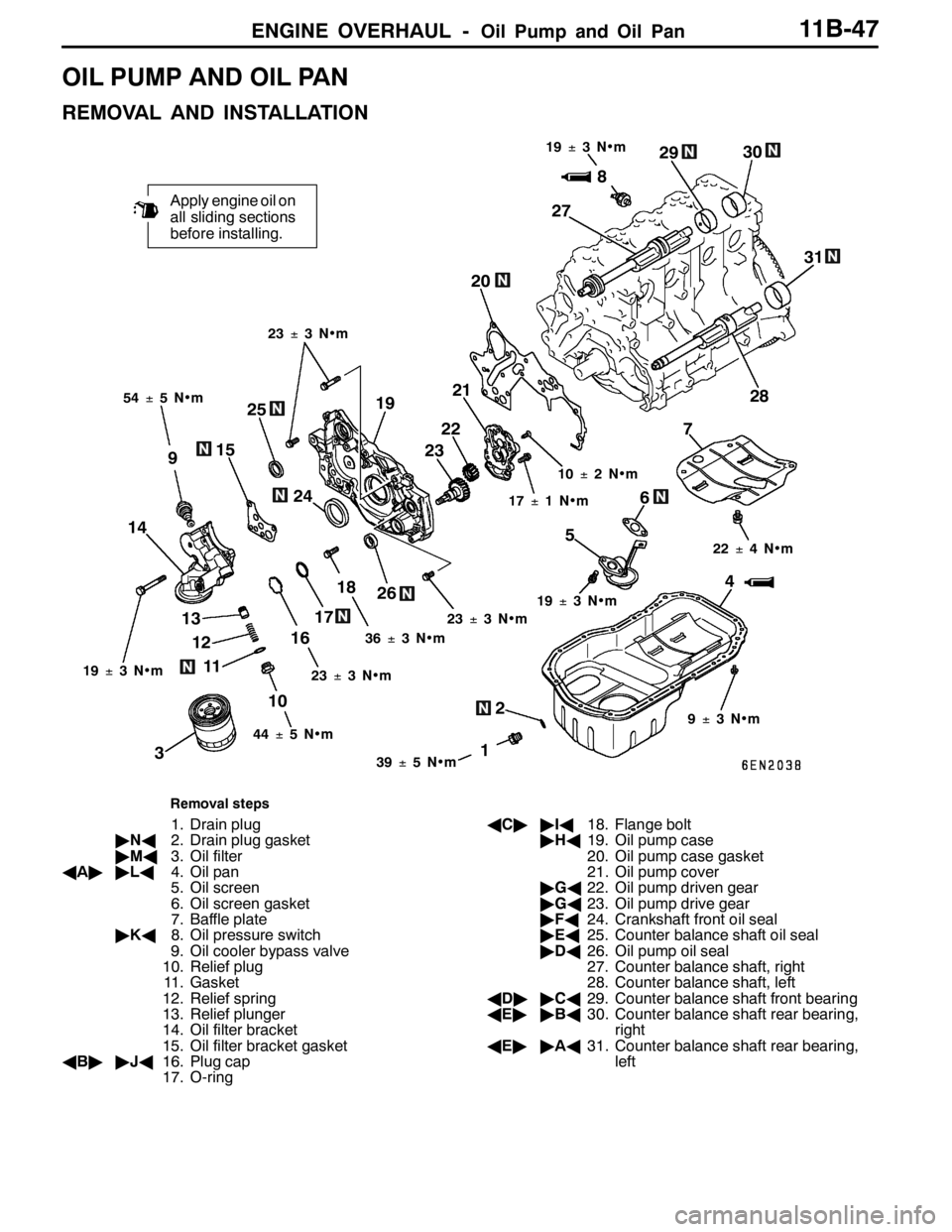
OIL PUMP AND OIL PAN
REMOVAL AND INSTALLATION
2
1
Apply engine oil on
all sliding sections
before installing.
4 56
12 13
16187 20
38
9
10 1415
1719
1139±5N•m 54±5N•m19±3N•m
36±3N•m23±3N•m 17±1N•m 10±2N•m
9±3N•m 22±4N•m 23±3N•m
19±3N•m
44±5N•m 23±3N•m
25
24232221
26272930
31
28
19±3N•m
Removal steps
1. Drain plug
"NA2. Drain plug gasket
"MA3. Oil filter
AA""LA4. Oil pan
5. Oil screen
6. Oil screen gasket
7. Baffle plate
"KA8. Oil pressure switch
9. Oil cooler bypass valve
10. Relief plug
11. Gasket
12. Relief spring
13. Relief plunger
14. Oil filter bracket
15. Oil filter bracket gasket
AB""JA16. Plug cap
17. O-ringAC""IA18. Flange bolt
"HA19. Oil pump case
20. Oil pump case gasket
21. Oil pump cover
"GA22. Oil pump driven gear
"GA23. Oil pump drive gear
"FA24. Crankshaft front oil seal
"EA25. Counter balance shaft oil seal
"DA26. Oil pump oil seal
27. Counter balance shaft, right
28. Counter balance shaft, left
AD""CA29. Counter balance shaft front bearing
AE""BA30. Counter balance shaft rear bearing,
right
AE""AA31. Counter balance shaft rear bearing,
left
Page 508 of 1449

ENGINE OVERHAUL -Oil Pump and Oil Pan11B-54
"MADRAIN PLUG GASKET INSTALLATION
Replace the gasket with a new part, and install at the direction
shown in the illustration.
Caution
Incorrect installation direction will lead to oil leaks.
"NAOIL FILTER INSTALLATION
1. Clean the installation surface on the cylinder block side.
2. Apply engine oil on the O-ring for the oil filter.
3. Screw in the oil filter, and tighten approx. 3/4 of a rotation
(approx. 14±2N•m) from where the O-ring contacts
the installation surface.
INSPECTION
1. COUNTER BALANCE SHAFT
(1) Make sure that the oil hole is not clogged.
(2) Check the journal (bearing section) for seizure or
damage, and check the state of contact with the
bearings. If any faults are found, replace the counter
balance shaft, bearing or oil pump case assembly.
2. OIL COOLER BYPASS VALVE
(1) The valve must move smoothly.
(2) The L dimension must be at the standard value at
a constant temperature, constant humidity state.
Standard value: 34.5 mm
(3) The protruded dimensions must be at the standard
value after submerging into 100_C oil.
Standard value: 40 mm
Drain plug
Oil pan
Oil pan side Gasket
Bracket side
L
Valve
Page 528 of 1449

ENGINE LUBRICATION -On-vehicle Service12-4
ON-VEHICLE SERVICE
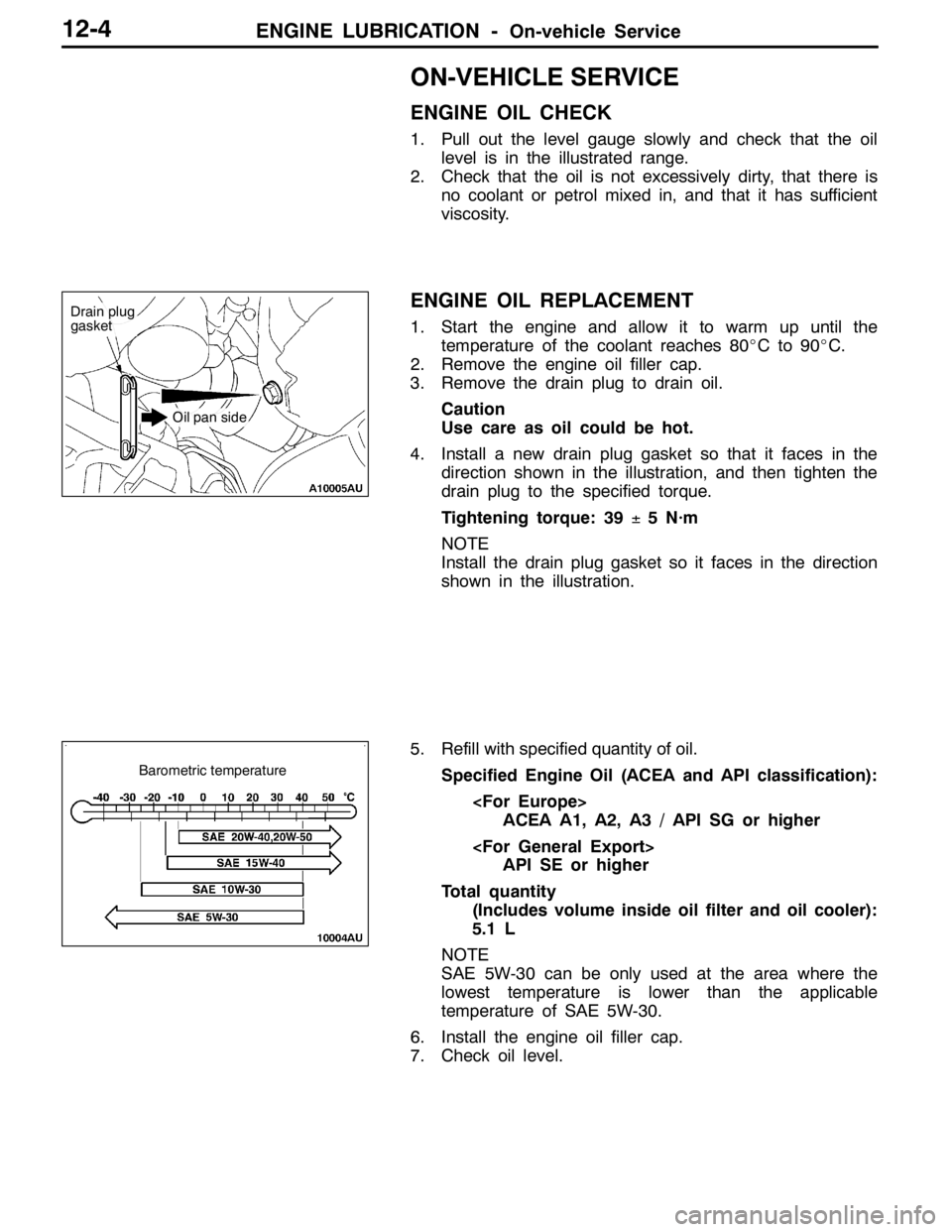
ENGINE OIL CHECK
1. Pull out the level gauge slowly and check that the oil
level is in the illustrated range.
2. Check that the oil is not excessively dirty, that there is
no coolant or petrol mixed in, and that it has sufficient
viscosity.
ENGINE OIL REPLACEMENT
1. Start the engine and allow it to warm up until the
temperature of the coolant reaches 80_Cto90_C.
2. Remove the engine oil filler cap.
3. Remove the drain plug to drain oil.
Caution
Use care as oil could be hot.
4. Install a new drain plug gasket so that it faces in the
direction shown in the illustration, and then tighten the
drain plug to the specified torque.
Tightening torque: 39±5 N·m
NOTE
Install the drain plug gasket so it faces in the direction
shown in the illustration.
5. Refill with specified quantity of oil.
Specified Engine Oil (ACEA and API classification):
ACEA A1, A2, A3 / API SG or higher
API SE or higher
Total quantity
(Includes volume inside oil filter and oil cooler):
5.1 L
NOTE
SAE 5W-30 can be only used at the area where the
lowest temperature is lower than the applicable
temperature of SAE 5W-30.
6. Install the engine oil filler cap.
7. Check oil level.
Drain plug
gasket
Oil pan side
Barometric temperature
Page 529 of 1449

ENGINE LUBRICATION -On-vehicle Service12-5
OIL FILTER REPLACEMENT
1. Start the engine and allow it to warm up until the
temperature of the coolant reaches 80_Cto90_C.
2. Remove the engine oil filler cap.
3. Remove the drain plug to drain oil.
Caution
Use care as oil could be hot.
4. Remove the under cover.
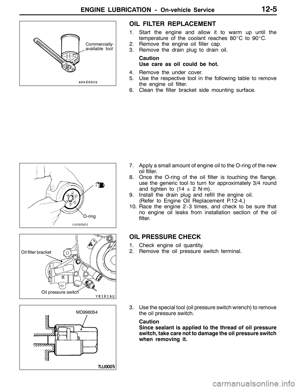
5. Use the respective tool in the following table to remove
the engine oil filter.
6. Clean the filter bracket side mounting surface.
7. Apply a small amount of engine oil to the O-ring of the new
oil filter.
8. Once the O-ring of the oil filter is touching the flange,
use the generic tool to turn for approximately 3/4 round
and tighten to (14±2 N·m).
9. Install the drain plug and refill the engine oil.
(Refer to Engine Oil Replacement P.12-4.)
10. Race the engine 2 - 3 times, and check to be sure that
no engine oil leaks from installation section of the oil
filter.
OIL PRESSURE CHECK
1. Check engine oil quantity.
2. Remove the oil pressure switch terminal.
3. Use the special tool (oil pressure switch wrench) to remove
the oil pressure switch.
Caution
Since sealant is applied to the thread of oil pressure
switch, take care not to damage the oil pressure switch
when removing it.
Commercially-
available tool
O-ring
Oil pressure switch
Oil filter bracket
MD998054