Page 938 of 1449
FRONT AXLE -Drive Shaft26-10
DRIVE SHAFT
REMOVAL AND INSTALLATION
Caution
1. If the vehicle is equipped with the Brembo disc brake, during maintenance, take care not to
contact the parts or tools to the caliper because the paint of caliper will be scratched. And
if there is brake fluid on the caliper, wipe out quickly.
2. For vehicles with ABS or ACD, do not strike the rotor for wheel speed sensor installed to
the B.J. outer race of drive shaft against other parts when removing or installing the drive
shaft. Otherwise the rotor for wheel speed sensor will be damaged.
Pre-removal and Post-installation Operation
DTransmission Fluid Draining
DTransfer Oil Draining (Refer to GROUP 22 –
On-vehicle Service.)Pre-removal and Post-installation Operation
DCheck the Dust Cover for cracks or damage by
pushing it with finger.
DTransfer Oil Filling (Refer to GROUP 22 –
On-vehicle Service.)
DTransmission Fluid Filling
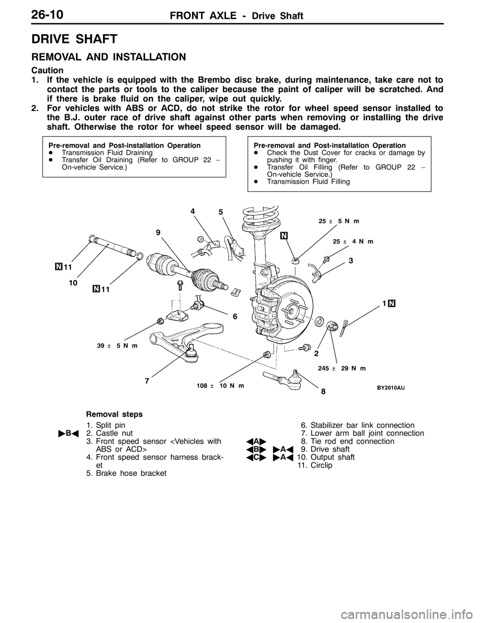
1
6 9
8 5
74
3
2 11
25�¶4N��m 25�¶5N��m
245�¶29 N��m
108�¶10 N��m
10
11
39�¶5N��m
Removal steps
1. Split pin
"BA2. Castle nut
3. Front speed sensor
ABS or ACD>
4. Front speed sensor harness brack-
et
5. Brake hose bracket6. Stabilizer bar link connection
7. Lower arm ball joint connection
AA"8. Tie rod end connection
AB""AA9. Drive shaft
AC""AA10. Output shaft
11. Circlip
Page 963 of 1449
REAR AXLE -On-vehicle Service27B-17
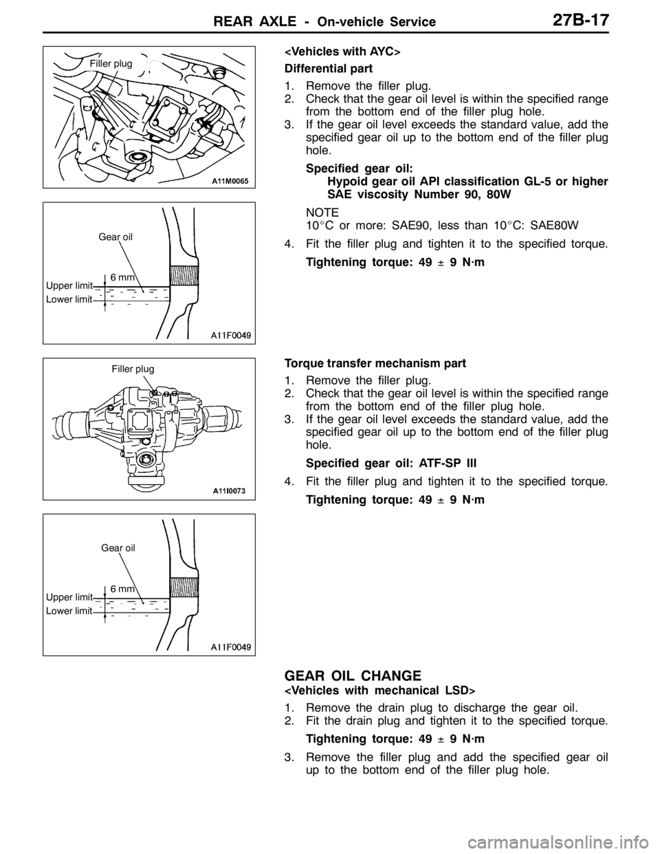
Differential part
1. Remove the filler plug.
2. Check that the gear oil level is within the specified range
from the bottom end of the filler plug hole.
3. If the gear oil level exceeds the standard value, add the
specified gear oil up to the bottom end of the filler plug
hole.
Specified gear oil:
Hypoid gear oil API classification GL-5 or higher
SAE viscosity Number 90, 80W
NOTE
10_C or more: SAE90, less than 10_C: SAE80W
4. Fit the filler plug and tighten it to the specified torque.
Tightening torque: 49±9 N·m
Torque transfer mechanism part
1. Remove the filler plug.
2. Check that the gear oil level is within the specified range
from the bottom end of the filler plug hole.
3. If the gear oil level exceeds the standard value, add the
specified gear oil up to the bottom end of the filler plug
hole.
Specified gear oil: ATF-SP III
4. Fit the filler plug and tighten it to the specified torque.
Tightening torque: 49±9 N·m
GEAR OIL CHANGE
1. Remove the drain plug to discharge the gear oil.
2. Fit the drain plug and tighten it to the specified torque.
Tightening torque: 49±9 N·m
3. Remove the filler plug and add the specified gear oil
up to the bottom end of the filler plug hole.
Filler plug
Upper limit
Lower limitGear oil
6mm
Filler plug
Upper limit
Lower limitGear oil
6mm
Page 964 of 1449
REAR AXLE -On-vehicle ServiceREAR AXLE -On-vehicle Service27B-18
Specified gear oil:
Hypoid gear oil
MITSUBISHI Genuine Gear Oil Part No. 8149630
EX, CASTROL HYPOY LS (GL-5, SAE 90),
SHELL-LSD (GL-5, SAE 80W - 90) or equivalent
Quantity: 0.55 L
4. Fit the filler plug and tighten it to the specified torque.
Tightening torque: 49±9 N·m
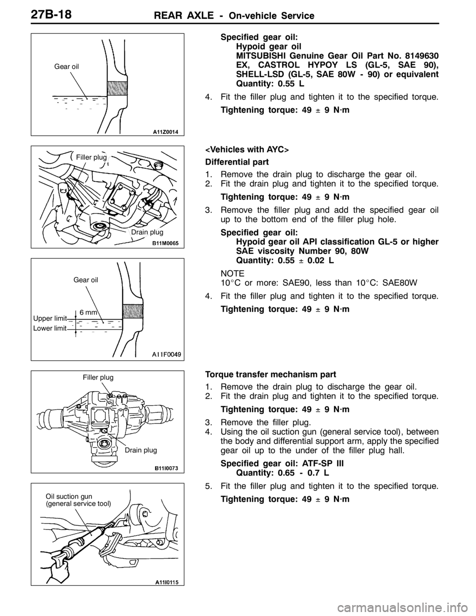
Differential part
1. Remove the drain plug to discharge the gear oil.
2. Fit the drain plug and tighten it to the specified torque.
Tightening torque: 49±9 N·m
3. Remove the filler plug and add the specified gear oil
up to the bottom end of the filler plug hole.
Specified gear oil:
Hypoid gear oil API classification GL-5 or higher
SAE viscosity Number 90, 80W
Quantity: 0.55±0.02 L
NOTE
10_C or more: SAE90, less than 10_C: SAE80W
4. Fit the filler plug and tighten it to the specified torque.
Tightening torque: 49±9 N·m
Torque transfer mechanism part
1. Remove the drain plug to discharge the gear oil.
2. Fit the drain plug and tighten it to the specified torque.
Tightening torque: 49±9 N·m
3. Remove the filler plug.
4. Using the oil suction gun (general service tool), between
the body and differential support arm, apply the specified
gear oil up to the under of the filler plug hall.
Specified gear oil: ATF-SP III
Quantity: 0.65 - 0.7 L
5. Fit the filler plug and tighten it to the specified torque.
Tightening torque: 49±9 N·m
Gear oil
Filler plug
Drain plug
Upper limit
Lower limitGear oil
6mm
Filler plug
Drain plug
Oil suction gun
(general service tool)
Page 971 of 1449
REAR AXLE -Rear Hub Assembly27B-25
REAR HUB ASSEMBLY
REMOVAL AND INSTALLATION
Caution
If the vehicle is equipped with the Brembo disc brake, during maintenance, take care not to contact
the parts or tools to the caliper because the paint of caliper will be scratched. And if there is
brake fluid on the caliper, wipe out quickly.
Pre-removal Operation
Gear Oil Draining (Refer to P. 27B-17.)Post-installation Operation
DGear Oil Filling (Refer to P. 27B-17.)
DParking Brake Lever Stroke Adjustment (Refer to
GROUP 36 – On-vehicle Service.)
2
118±19 N·m
4
1
3
225±25 N·m
8
7
6
5
10
9
54±5 N·m
81±6 N·m
Removal steps
AA"1. Rear brake caliper
2. Rear brake disc
3. Parking brake shoe & lining assembly
(Refer to GROUP 36 - Parking Brake
Drum.)
4. Clip5. Parking brake cable connection
6. Split pin
AB""AA7. Drive shaft nut
8. Rear drive shaft assembly
AC"9. Rear hub assembly
10. Backing plate
Page 975 of 1449
REAR AXLE -Drive Shaft27B-29
DRIVE SHAFT
REMOVAL AND INSTALLATION
Caution
1. If the vehicle is equipped with the Brembo disc brake, during maintenance, take care not to
contact the parts or tools to the caliper because the paint of caliper will be scratched. And
if there is brake fluid on the caliper, wipe out quickly.
2. With the part marked with *, first temporarily tighten it, then ground the vehicle and tighten
it to specification in unloaded condition.
Pre-removal Operation
DGear Oil Draining (Refer to P.27-17.)
DCenter Exhaust Pipe Removal (Refer to GROUP
15.)Post-installation Operation
DPress dust cover with a finger to check for crack
or damage in the dust cover.
DCenter Exhaust Pipe Installation (Refer to GROUP
15.)
DGear Oil Filling (Refer to P.27-17.)
DParking Brake Lever Stroke Check and Adjustment
DWheel Alignment Check and Adjustment (Refer to
GROUP 34 – On-vehicle Service.)
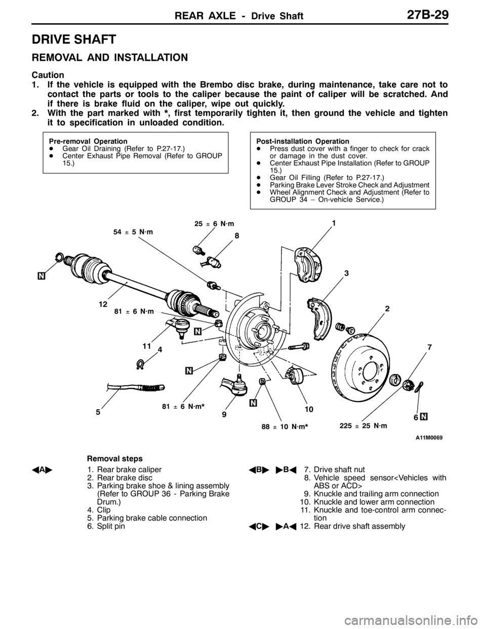
4
1
3
7
6510
2
8
9
11
12
225±25 N·m
54±5 N·m
88±10 N·m*
81±6 N·m*
81±6 N·m
25±6 N·m
Removal steps
AA"1. Rear brake caliper
2. Rear brake disc
3. Parking brake shoe & lining assembly
(Refer to GROUP 36 - Parking Brake
Drum.)
4. Clip
5. Parking brake cable connection
6. Split pinAB""BA7. Drive shaft nut
8. Vehicle speed sensor
ABS or ACD>
9. Knuckle and trailing arm connection
10. Knuckle and lower arm connection
11. Knuckle and toe-control arm connec-
tion
AC""AA12. Rear drive shaft assembly
Page 981 of 1449

REAR AXLE -Differential Carrier 27B-35
DIFFERENTIAL CARRIER
REMOVAL AND INSTALLATION
Pre-removal Operation
DDifferential Gear Oil Draining (Refer to P.27B-17.)
DLower Arm Assembly Removal (Refer to GROUP
34.)
DRear Stabilizer Removal (Refer to GROUP 34.)
DDrive Shaft Removal (Refer to P. 27B-29.)Post-installation Operation
DDrive Shaft Installation (Refer to P. 27B-29.)
DRear Stabilizer Installation (Refer to GROUP 34.)
DLower Arm Assembly Installation (Refer to GROUP
34.)
DDifferential Gear Oil Filling (Refer to P.27B-17.)
12
765
4 8 910
32�¶2N��m
2
3
3 3
3
76
9
120±10 N·m
88±10 N·m
69±9 N·m
88±10 N·m
88±10 N·m
88±10 N·m
120±10 N·m
120±10 N·m
120±10 N·m
69±9 N·m
88±10 N·m
Removal steps
AA"1. Propeller shaft connection (Refer to
GROUP 25.)
2. Toe control bar
3. Differential support member mount-
ing boots and nuts
AB""AA4. Rear crossmember and differential
carrier assembly5. Differential support member
6. Upper stopper
7. Lower stopper
8. Differential support arm
9. Differential mount bracket
10. Differential carrier assembly
Page 984 of 1449
REAR AXLE -Differential Carrier 27B-38
DISASSEMBLY
19
2
6
8
20
22
26
5
113
4
9
12
15
16
1314
10
21
1
23
24
25
18
17
7
897
Disassembly steps
AA"DInspection before disassembly
1. Filler plug
2. Drain plug
3. Differential cover assembly
4. Vent plug
5. Bearing cap
AB"6. Differential case assembly
AB"7. Side bearing spacer
AB"8. Side bearing outer race
AC"9. Side bearing inner race
AD"10. Drive gear
11. Limited slip differential case assembly*
AE"12. Self-locking nut
13. Washer
AF"14. Drive pinion assemblyAF"15. Companion flange
16. Drive pinion front shim (For adjusting
preload of drive pinion)
17. Drive pinion spacer
AG"18. Drive pinion rear bearing inner race
19. Drive pinion rear shim (For adjusting
drive pinion height)
20. Drive pinion
AH"21. Oil seal
AH"22. Drive pinion front bearing inner race
AH"23. Drive pinion front bearing outer race
AI"24. Drive pinion rear bearing outer race
25. Oil seal
26. Differential carrier
Page 989 of 1449
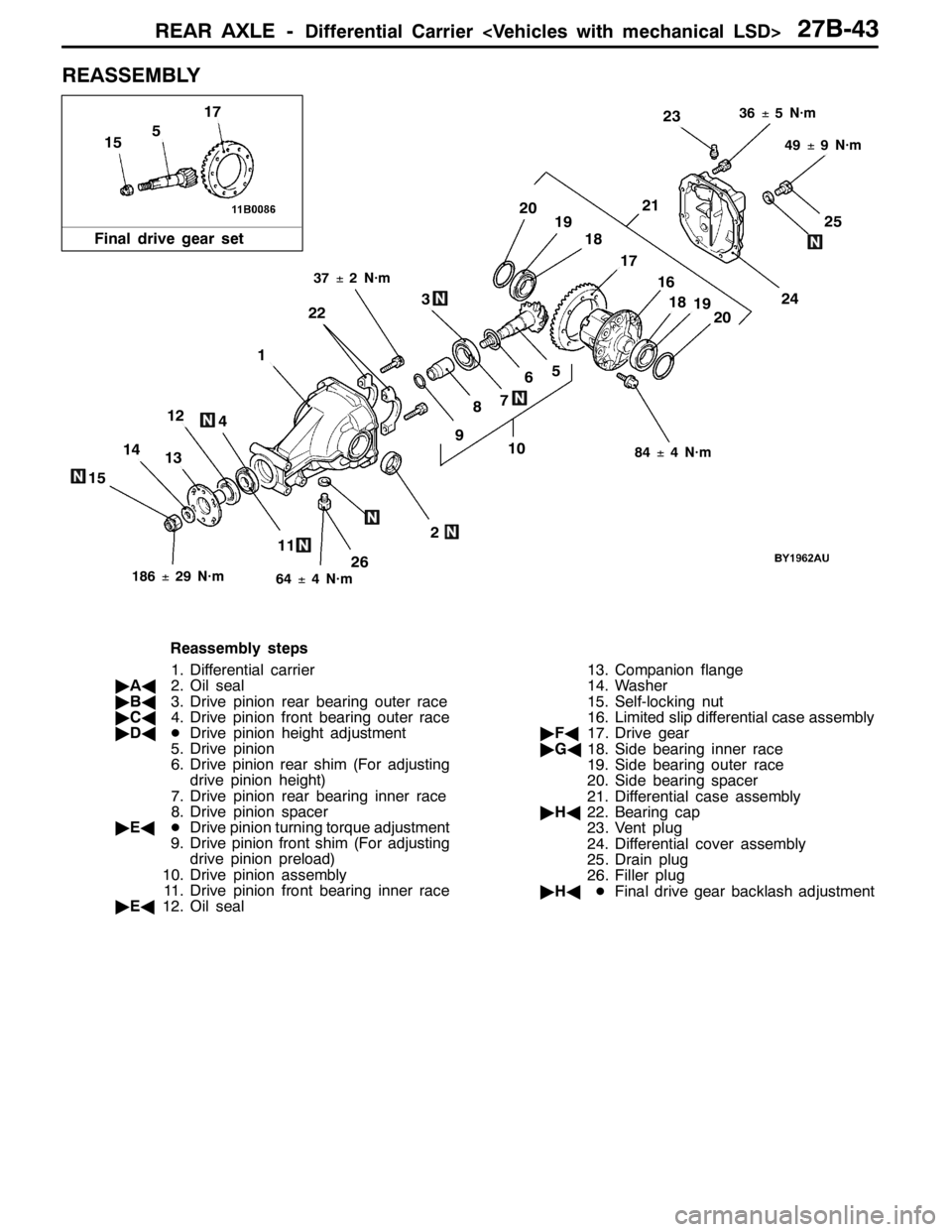
REAR AXLE -Differential Carrier 27B-43
REASSEMBLY
11
14
26
25
1310
6
124
7
24
21
18
17
15
2019
9
3
8
5
2
1
22
23
16
191820
5
17
15
84±4 N·m
186±29 N·m64±4 N·m
49±9 N·m
37±2 N·m
36±5 N·m
Final drive gear set
Reassembly steps
1. Differential carrier
"AA2. Oil seal
"BA3. Drive pinion rear bearing outer race
"CA4. Drive pinion front bearing outer race
"DADDrive pinion height adjustment
5. Drive pinion
6. Drive pinion rear shim (For adjusting
drive pinion height)
7. Drive pinion rear bearing inner race
8. Drive pinion spacer
"EADDrive pinion turning torque adjustment
9. Drive pinion front shim (For adjusting
drive pinion preload)
10. Drive pinion assembly
11. Drive pinion front bearing inner race
"EA12. Oil seal13. Companion flange
14. Washer
15. Self-locking nut
16. Limited slip differential case assembly
"FA17. Drive gear
"GA18. Side bearing inner race
19. Side bearing outer race
20. Side bearing spacer
21. Differential case assembly
"HA22. Bearing cap
23. Vent plug
24. Differential cover assembly
25. Drain plug
26. Filler plug
"HADFinal drive gear backlash adjustment