Page 1123 of 1449

STEERING -On-vehicle Service37A-9
POWER STEERING FLUID LEVEL CHECK
1. Park the vehicle on a flat, level surface, start the engine,
and then turn the steering wheel several times to raise
the temperature of the fluid to approximately 50 - 60_C.
2. With the engine running, turn the wheel all the way to
the left and right several times.
3. Check the fluid in the oil reservoir for foaming or milkiness.
Check the difference of the fluid level when the engine
is stopped, and while it is running. If the change of the
fluid level is 5 mm or more, air bleeding should be done.
POWER STEERING FLUID REPLACEMENT
1. Raise the front wheels on a jack, and then support them
with rigid racks.
2. Disconnect the return hose connection.
3. Connect a vinyl hose to the return hose, and drain the
oil into a container.
4. Disconnect the ignition coil connectors. (Refer to
GROUP16 - Ignition System.)
5. While operating the starting motor intermittently, turn the
steering wheel all the way to the left and right several
times to drain all of the fluid.
6. Connect the return hoses securely, and then secure it
with the clip.
7. Fill the oil reservoir with specified fluid up to the lower
position of the filter, and then bleed air.
Specified fluid:
Automatic transmission fluid DEXRONII
Caution
Do not use ATF-SPIIM and ATF-SPIII.
POWER STEERING SYSTEM BLEEDING
1. Jack up the vehicle and support the front wheels with
rigid racks.
2. Disconnect the ignition coil connectors. (Refer to
GROUP16 - Ignition System.)
3. Cranking the engine with the starter several times
intermittently (during 15 to 20 seconds), turn the steering
wheel left and right fully five or six times.
Caution
(1) During the bleeding, refill the fluid so that the
level never falls below the lower position of the
filter.
(2) Be sure to bleed air only while cranking. If the
bleeding is done with the engine running, the air
will be broken up and absorbed into the fluid.
4. Connect the ignition coil connectors and idle the engine.
5. Turn the steering wheel left and right fully until no bubbles
comes out in the oil reservoir.
6. See that the fluid is not milky and that the fluid level
is up to the specified position on the level gauge.
7. See that the fluid level changes little when the steering
wheel is turned left and right.
8. Check difference in fluid levels between the engine
stopped and running.
Fluid level change: Within 5 mm
While engine
runningWhile engine
stopped
Return hose
Vinyl hose
Page 1130 of 1449

STEERING - Power Steering Gear Box and Linkage37A-16
POWER STEERING GEAR BOX AND LINKAGE
REMOVAL AND INSTALLATION
Caution: SRS
Before removing steering gear box, refer to GROUP 52B. Also, put the front wheels in straight-ahead
position. Failure to do so may damage the SRS clock spring and render the SRS air bag inoperative,
which results serious driver injury.
Caution
If the vehicle is equipped with the Brembo disc brake, during maintenance, take care not to contact
the parts or tools to the caliper because the paint of caliper will be scratched. And if there is
brake fluid on the caliper, wipe out quickly.
Pre-removal Operation
DClock Spring Removal (Refer to GROUP 52B.)
DPower Steering Fluid Draining (Refer to P.37A-9.)Post-installation Operation
DClock Spring Installation (Refer to GROUP 52B.)
DPower Steering Fluid Supplying and bleeding
(Refer to P.37A-9.)
DChecking Steering Wheel Position with Wheels
Straight Ahead
17
6
3 4
57±7 N·m5
8
70±10 N·m
2
15±3 N·m
9
10
12±2 N·m 12±2 N·m
70±10 N·m
Removal steps
1. Crossmember
(Refer to GROUP 32.)
DRear roll stopper(Refer to GROUP 32.)
2. Joint cover grommet
3. Return hose
4. Return tube5. O ring
6. Return tube
7. Eye bolt
8. Pressure hose assembly
9. Clamp
10. Steering gear and linkage
Page 1143 of 1449
STEERING - Power Steering Oil Pump37A-29
POWER STEERING OIL PUMP
REMOVAL AND INSTALLATION
Caution
After temporary tightening all bolts in * part, tighten in specific torque.
Pre-removal Operation
Power Steering Fluid Draining (Refer to P.37A-9.)Post-installation Operation
DPower Steering Fluid Supplying and Bleeding
(Refer to P.37A-9.)
DDrive Belt Tension Adjusting
(Refer to GROUP 11A – On-vehicle Service.)
22±4 N·m
8
40±5 N·m 18±3 N·m
3
45
2
5
22±4 N·m*
1 7
6
40±5 N·m* 22±4 N·m
Removal steps
1. Pressure switch connector
2. Drive belt (Refer to GROUP 11A.)
"BA3. Suction hose connection
"BA4. Pressure hose connection"AA5. O ring
6. Heat protecter
7. Oil pump assembly
8. Power steering pump bracket
INSTALLATION SERVICE POINTS
"AAO-RING INSTALLATION
No.ID×Width mm
111.0×1.9
213.0×1.9
21
Page 1145 of 1449
STEERING - Power Steering Oil Hoses37A-31
Pre-removal and Post-installation Operation
Power Steering Fluid Draining and Refilling (Refer to
P.37A-9.)
12±2 N·m
17
16
15
12
18±3 N·m
Crossmember
1
57±7 N·m
9
8 47
32 5
12±2 N·m15±3 N·m
18±2 N·m 12±2 N·m
49±10 N·m
52±7 N·m*
12±2 N·m
6
10
11
167±10 N·m
14 13
18
12±2 N·m
12±2 N·m
Removal steps
1. Oil reservoir
"BA2. Suction hose
3. Return hose
4. Return hose
5. Return tube
DStrut tower bar (Refer to GROUP 42.)
6. Return hose
DClock spring (Refer to GROUP 52B.)
DCrossmember bar
(Refer to GROUP 33A.)
DCenter member (Refer to GROUP 32.)
DFront exhaust pipe
(Refer to GROUP 15.)
7. Steering gear and joint connecting
bolt8. Rear roll stopper connecting bolt
9. Rear roll stopper
(Refer to GROUP 32.)
AA"10. Eye bolt
11. Gasket
"BA12. Pressure hose assembly
"AA13. O ring
14. Return hose
15. Return tube
AA"16. Return tube
17. O ring
DFront bumper (Refer to GROUP 51.)
DIntercooler (Refer to GROUP 15.)
18. Cooler tube assembly
Page 1146 of 1449
STEERING - Power Steering Oil Hoses37A-32
Pre-removal and Post-installation Operation
Power Steering Fluid Draining and Refilling (Refer to
P.37A-9.)
12±2 N·m
15
12
18±3 N·m
Crossmember
1
57±7 N·m
9
8 4
7
32 5
12±2 N·m
15±3 N·m
18±2 N·m 12±2 N·m
49±10 N·m
52±7 N·m*
12±2 N·m
6
10
11
167±10 N·m
14
13
12±2 N·m
Removal steps
1. Oil reservoir
"BA2. Suction hose
3. Return hose
4. Return hose
5. Return tube
DStrut tower bar (Refer to GROUP 42.)
6. Return hose
DClock spring (Refer to GROUP 52B.)
DCrossmember bar
(Refer to GROUP 33A.)
DCenter member (Refer to GROUP 32.)
DFront exhaust pipe
(Refer to GROUP 15.)7. Steering gear and joint connecting
bolt
8. Rear roll stopper connecting bolt
AA"9. Eye bolt
10. Gasket
"BA11. Pressure hose assembly
"AA12. O ring
AA"13. Return tube
14. O ring
DFront bumper (Refer to GROUP 51.)
DIntercooler (Refer to GROUP 15.)
15. Cooler tube assembly
Page 1341 of 1449

CHASSIS ELECTRICAL -Combination Meter54A-21
FLOAT HEIGHT OF FUEL GAUGE UNIT
When float is moved to contact float arm on stopper,
ensure that Position F (A) and E (B) are within standard
value.
Standard Value:
FloatPositionMainfuelgaugeunitSubfuelgaugeunitFloatPositionMainfuelgaugeunitSubfuelgaugeunit
Position F (A)33.3 mm10.7 mm
Position E (B)121.9 mm138.6 mm
ENGINE COOLANT TEMPERATURE GAUGE
UNIT CHECK
1. Drain coolant. (Refer to GROUP 14 - On-vehicle Service)
2. Remove water temperature gauge unit.
3. Put water temperature gauge unit into the hot water in
specified temperature, and ensure that basic resistance
is within standard value.
Standard value: 70_C 104±13.5Ω
Reference value:
TemperatureResistanceΩ
50_C230
60_C155
80_C73
4. After inspection, apply specified sealant at threads of
water temperature gauge unit, and tighten to the specified
torque.
Semi-drying sealant: 3M ATD Part No.1215 or
equivalent
5. Refill coolant. (Refer to GROUP 14 - On-vehicle Service.)
Main fuel gauge unit
Sub fuel gauge unit
A
B
A
B
ThermometerCircuit tester
11±1 N·m
Page 1416 of 1449

HEATER, AIR CONDITIONER AND VENTILATION–On-vehicle Service55-14
ON-VEHICLE SERVICE
REFRIGERANT LEVEL TEST THROUGH
PERFORMANCE TEST
1. Start the engine.
2. Turn on the A/C switch, and set the A/C control to MAX.
COOL.
3. Adjust the engine speed to 1,500 r/min.
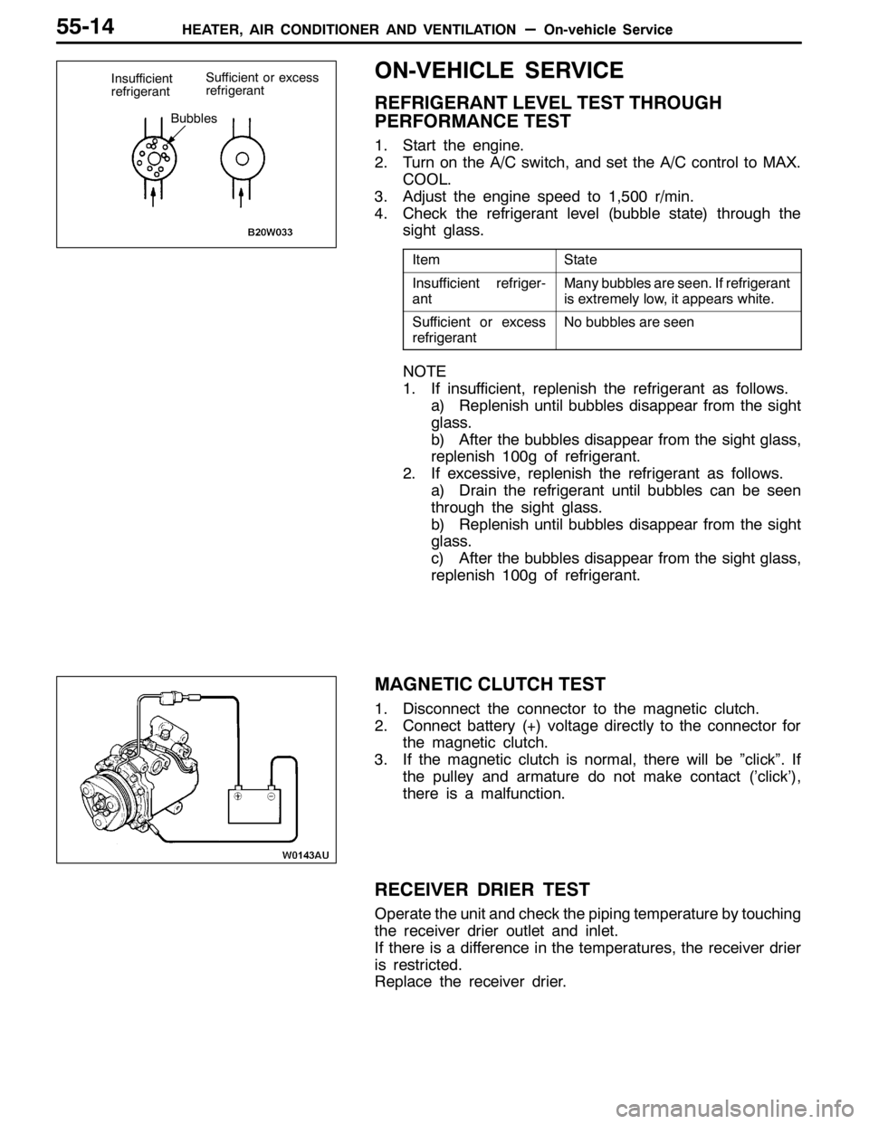
4. Check the refrigerant level (bubble state) through the
sight glass.
ItemState
Insufficient refriger-
antMany bubbles are seen. If refrigerant
is extremely low, it appears white.
Sufficient or excess
refrigerantNo bubbles are seen
NOTE
1. If insufficient, replenish the refrigerant as follows.
a) Replenish until bubbles disappear from the sight
glass.
b) After the bubbles disappear from the sight glass,
replenish 100g of refrigerant.
2. If excessive, replenish the refrigerant as follows.
a) Drain the refrigerant until bubbles can be seen
through the sight glass.
b) Replenish until bubbles disappear from the sight
glass.
c) After the bubbles disappear from the sight glass,
replenish 100g of refrigerant.
MAGNETIC CLUTCH TEST
1. Disconnect the connector to the magnetic clutch.
2. Connect battery (+) voltage directly to the connector for
the magnetic clutch.
3. If the magnetic clutch is normal, there will be ”click”. If
the pulley and armature do not make contact (’click’),
there is a malfunction.
RECEIVER DRIER TEST
Operate the unit and check the piping temperature by touching
the receiver drier outlet and inlet.
If there is a difference in the temperatures, the receiver drier
is restricted.
Replace the receiver drier.
Insufficient
refrigerantSufficient or excess
refrigerant
Bubbles
Page 1430 of 1449

HEATER, AIR CONDITIONER AND VENTILATION-Heater Unit and Blower Assembly55-28
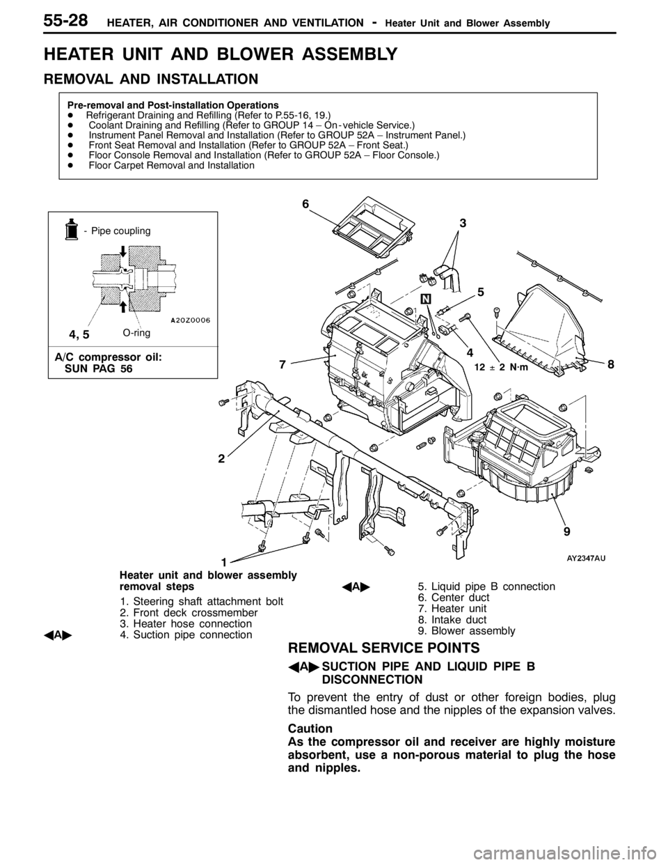
HEATER UNIT AND BLOWER ASSEMBLY
REMOVAL AND INSTALLATION
Pre-removal and Post-installation Operations
DRefrigerant Draining and Refilling (Refer to P.55-16, 19.)
DCoolant Draining and Refilling (Refer to GROUP 14 – On - vehicle Service.)
DInstrument Panel Removal and Installation (Refer to GROUP 52A – Instrument Panel.)
DFront Seat Removal and Installation (Refer to GROUP 52A – Front Seat.)
DFloor Console Removal and Installation (Refer to GROUP 52A – Floor Console.)
DFloor Carpet Removal and Installation
13
5 6
2
12±2 N·m
- Pipe coupling
O-ring
A/C compressor oil:
SUN PAG 56
4, 5
9
7
4
8
Heater unit and blower assembly
removal steps
1. Steering shaft attachment bolt
2. Front deck crossmember
3. Heater hose connection
AA"4. Suction pipe connectionAA"5. Liquid pipe B connection
6. Center duct
7. Heater unit
8. Intake duct
9. Blower assembly
REMOVAL SERVICE POINTS
AA"SUCTION PIPE AND LIQUID PIPE B
DISCONNECTION
To prevent the entry of dust or other foreign bodies, plug
the dismantled hose and the nipples of the expansion valves.
Caution
As the compressor oil and receiver are highly moisture
absorbent, use a non-porous material to plug the hose
and nipples.