2007 MITSUBISHI LANCER EVOLUTION heater
[x] Cancel search: heaterPage 647 of 1449

MPI -Troubleshooting13A-115
Terminal No. Normal condition (Check condition)Inspection item
3-12Fuel pressure control solenoid valve28 - 36Ω(at 20_C)
4-12Stepper motor coil (A1)28 - 33Ω(at 20_C)
17 - 12Stepper motor coil (A2)
5-12Stepper motor coil (B1)
18 - 12Stepper motor coil (B2)
6-12EGR control solenoid valve36 - 44Ω(at 20_C)
9-12Purge control solenoid valve22 - 26Ω(at 20_C)
11 - 1 2Waste gate solenoid valve62 - 74Ω(at 20_C)
13 - Body earthENGINE-ECU earthContinuity (0Ω)
26 - Body earthENGINE-ECU earth
53 - 12Secondary air control solenoid valve28 - 36Ω(at 20_C)
54 - 12Oxygen sensor heater (Rear)11 - 1 8Ω(at 20_C)
60 - 12Oxygen sensor heater (Front)4.5 - 8.0Ω(at 20_C)
72 - 92Intake air temperature sensor13 - 17 kΩ(When intake air temperature is - 20_C)
5.7 - 6.7 kΩ(When intake air temperature is 0_C)
2.3 - 3.0 kΩ(When intake air temperature is 20_C)
1.0 - 1.5 kΩ(When intake air temperature is 40_C)
0.56 - 0.76 kΩ(When intake air temperature is 60_C)
0.30 - 0.42 kΩ(When intake air temperature is 80_C)
83 - 92Engine coolant temperature sensor14 - 17 kΩ(When coolant temperature is - 20_C)
5.1 - 6.5 kΩ(When coolant temperature is 0_C)
2.1 - 2.7 kΩ(When coolant temperature is 20_C)
0.9 - 1.3 kΩ(When coolant temperature is 40_C)
0.48 - 0.68 kΩ(When coolant temperature is 60_C)
0.26 - 0.36 kΩ(When coolant temperature is 80_C)
Page 702 of 1449

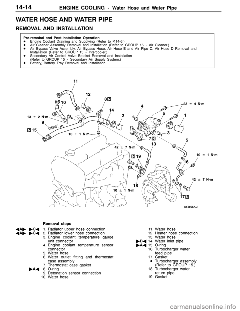
ENGINE COOLING -Water Hose and Water Pipe14-14
WATER HOSE AND WATER PIPE
REMOVAL AND INSTALLATION
Pre-remobal and Post-installation Operation
DEngine Coolant Draining and Supplying (Refer to P.14-6.)
DAir Cleaner Assembly Removal and Installation (Refer to GROUP 15 - Air Cleaner.)
DAir Bypass Valve Assembly, Air Bypass Hose, Air Hose E and Air Pipe C, Air Hose D Removal and
Installation (Refer to GROUP 15 - Intercooler.)
DSecondary Air Control Valve Bracket Removal and Installation
(Refer to GROUP 15 - Secondary Air Supply System.)
DBattery, Battery Tray Removal and Installation
3 4
5 6
7 8
9
1012
10±1 N·m
42±7 N·m 13±2 N·m
11
1
2
23±4 N·m
18
1716 1514
13
19
10±1 N·m
42±7 N·m
10±1 N·m
Removal steps
AA""CA1. Radiator upper hose connection
AA""CA2. Radiator lower hose connection
3. Engine coolant temperature gauge
unit connector
4. Engine coolant temperature sensor
connector
5. Water hose
6. Water outlet fitting and thermostat
case assembly
7. Thermostat case gasket
"AA8. O-ring
9. Detonation sensor connection
10. Water hose11. Water hose
12. Heater hose connection
13. Water hose
"BA14. Water inlet pipe
"AA15. O-ring
16. Turbocharger water
feed pipe
17. Gasket
DTurbocharger assembly
(Refer to GROUP 15.)
18. Turbocharger water
return pipe
19. Gasket
Page 738 of 1449

ENGINE ELECTRICAL -Charging System16-6
This test determines whether the alternator output
current is normal.
(1) Before the test, always be sure to check the
following.
DAlternator installation
DBattery (Refer to GROUP 54 - Battery.)
NOTE
The battery should be slightly discharged.
The load needed by a fully-charged battery
is insufficient for an accurate test.
DAlternator drive belt tension
(Refer to GROUP 11 - On-vehicle Service.)
DFusible link
DAbnormal noise from the alternator while
the engine is running.
(2) Turn the ignition switch to the “LOCK” (OFF)
position.
(3) Disconnect the negative battery cable.
(4) Disconnect the alternator output wire from the
alternator “B” terminal. Connect a DC test
ammeter with a range of 0 - 100 A in series
between the “B” terminal and the disconnected
output wire. (Connect the (+) lead of the
ammeter to the “B” terminal. Connect the ( - )
lead of the ammeter to the disconnected output
wire.)
Caution
Never use clips but tighten bolts and nuts
to connect the line. Otherwise loose
connections (e.g. using clips) will lead to
a serious accident because of high current.
NOTE
An inductive-type ammeter which enables
measurements to be taken without
disconnecting the alternator output wire should
be recommended.
(5) Connect a voltmeter with a range of 0 - 20 V
between the alternator “B” terminal and the
earth. (Connect the (+) lead of the voltmeter
to the “B” terminal, and then connect the ( - )
lead of the voltmeter to the earth.)
(6) Connect the negative battery cable.
(7) Connect a tachometer or the MUT-II.
(Refer to GROUP 11 - On-vehicle Service.)
(8) Leave the hood open.
(9) Check that the reading on the voltmeter is equal
to the battery voltage.
NOTE
If the voltage is 0 V, the cause is probably
an open circuit in the wire or fusible link between
the alternator “B” terminal and the battery (+)
terminal.(10)Turn the light switch on to turn on headlamps
and then start the engine.
(11) Immediately after setting the headlamps to high
beam and turning the heater blower switch to
the high revolution position, increase the engine
speed to 2,500 r/min and read the maximum
current output value displayed on the ammeter.
Limit: 70 % of normal current output
NOTE
DFor the nominal current output, refer to the
Alternator Specifications.
DBecause the current from the battery will
soon drop after the engine is started, the
above step should be carried out as quickly
as possible in order to obtain the maximum
current output value.
DThe current output value will depend on
the electrical load and the temperature of
the alternator body.
DIf the electrical load is small while testing,
the specified level of current may not be
output even though the alternator is normal.
In such cases, increase the electrical load
by leaving the headlamps turned on for
some time to discharge the battery or by
using the lighting system in another vehicle,
and then test again.
DThe specified level of current also may not
be output if the temperature of the alternator
body or the ambient temperature is too
high. In such cases, cool the alternator and
then test again.
(12)The reading on the ammeter should be above
the limit value. If the reading is below the limit
value and the alternator output wire is normal,
remove the alternator from the engine and
check the alternator.
(13)Run the engine at idle after the test.
(14)Turn the ignition switch to the “LOCK” (OFF)
position.
(15)Remove the tachometer or the MUT-II.
(16)Disconnect the negative battery cable.
(17)Disconnect the ammeter and voltmeter.
(18)Connect the alternator output wire to the
alternator “B” terminal.
(19)Connect the negative battery cable.
Page 1222 of 1449

INTERIOR -Instrument Panel52A-4
Caution: SRS
1. Refer to GROUP 52B-SRS Service Precautions and Air bag Module and Clock Spring before
removing the passenger side air bag module.
2. Do not subject the SRS-ECU to any shocks when removing or installing the instrument panel.
Pre-removal and Post-installation Operation
DRemoval and Installation of Front Pillar Trim (Refer
to P.52A-15.)
DFood Opener Lever (Refer to GROUP42.)
22 22
23
19
20 24
1817 11
12
10 6
7
1315 4
16 8 9
5
21 14 13 2
b b
d
d c
bdd
bd d
ad
ca
d
a25
d
Removal steps
1. Column cover
2. Meter bezel
3. Combination meter
4. Instrument panel ornament
5. Under cover
6. Box
7. Switch panel
8. Side box
9. Lower frame
10. Heater control knob
11. Heater control assembly mounting
screw
12. Center panel
13. Heater control panel assembly
14. Radio plug15. Center air outlet panel
16. Center lower box
17. Center lower case
18. Center lower box
19. Stopper
20. Glove box
21. Harness cover
22. Instrument panel side cover
23. SRS front passenger’s air bag module
mounting bolt
DSteering column shaft mounting bolt
(Refer to GROUP37A – Steering
Wheel and Shaft.)
24. Instrument panel assembly
AA"25. SRS front passenger’s air bag module
Page 1225 of 1449

INTERIOR -Instrument PanelINTERIOR -Instrument Panel52A-7
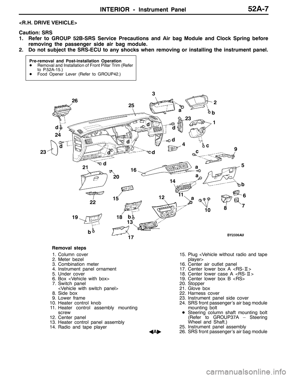
Caution: SRS
1. Refer to GROUP 52B-SRS Service Precautions and Air bag Module and Clock Spring before
removing the passenger side air bag module.
2. Do not subject the SRS-ECU to any shocks when removing or installing the instrument panel.
Pre-removal and Post-installation Operation
DRemoval and Installation of Front Pillar Trim (Refer
to P.52A-15.)
DFood Opener Lever (Refer to GROUP42.)
2023
21
18 22
1711
12
106
7
13 154
16
89
5
19141 b
d
d
c
d
a
b dd
d
a d
c a
d
a 232425 26
b
b
3
d2
Removal steps
1. Column cover
2. Meter bezel
3. Combination meter
4. Instrument panel ornament
5. Under cover
6. Box
7. Switch panel
8. Side box
9. Lower frame
10. Heater control knob
11. Heater control assembly mounting
screw
12. Center panel
13. Heater control panel assembly
14. Radio and tape player15. Plug
16. Center air outlet panel
17. Center lower box A
18. Center lower case A
19. Center lower box B
20. Stopper
21. Glove box
22. Harness cover
23. Instrument panel side cover
24. SRS front passenger’s air bag module
mounting bolt
DSteering column shaft mounting bolt
(Refer to GROUP37A – Steering
Wheel and Shaft.)
25. Instrument panel assembly
AA"26. SRS front passenger’s air bag module
Page 1294 of 1449

SRS - SRS-ECU52B-50
SRS AIR BAG CONTROL UNIT (SRS-ECU)
Caution
1. Disconnect the negative ( - ) battery terminal
and wait for 60 seconds or more before
starting work. Also, the disconnected
battery terminal should be insulated with
tape. (Refer to P.52B-3.)
2. Never attempt to disassemble or repair the
SRS-ECU. If faulty, just replace with a new
one.3. Do not drop or subject the SRS-ECU to
impact or vibration.
If denting, cracking, deformation, or rust are
found in the SRS-ECU, replace it with a new
one. Discard the old one.
4. After deployment of the air bags, replace
the SRS-ECU with a new one.
5. Never use an ohmmeter on or near the
SRS-ECU, and use only the special test
equipment described on P.52B-6.
REMOVAL AND INSTALLATION
Pre-removal Operation
DTurn Ignition Key to LOCK (OFF) Position.
DDisconnect the Negative ( - ) Battery Terminal.
12
4.9±1.0 N·m
4.9±1.0 N·m
4.9±1.0 N·m
3
Removal steps
DFront floor console
(Refer to GROUP 52A - Front floor
console.)
DRear heater duct B
1. SRS-ECU and SRS-ECU bracket
assembly
2. SRS-ECU
3. SRS-ECU bracketInstallation steps
3. SRS-ECU bracket
"AA2. SRS-ECU
1. SRS-ECU and SRS-ECU bracket
assembly
DRear heater duct B
DFront floor console
(Refer to GROUP 52A - Front floor
console.)
DNegative ( - ) battery terminal
connection
"BADPost-installation inspection
Page 1323 of 1449

54A-3
SIDE TURN-SIGNAL LAMP 31............
SPECIAL TOOL 31............................
SIDE TURN-SIGNAL LAMP 31..................
ROOM LAMP 31.........................
TROUBLESHOOTING 31.......................
REAR COMBINATION LAMP 32...........
SPECIAL TOOL 32............................
TROUBLESHOOTING 32.......................
REAR COMBINATION LAMP 32................
HIGH-MOUNTED STOP LAMP 34.........
ON-VEHICLE SERVICE 34......................
High-mounted Stop Lamp Bulb Replacement 34.
HIGH-MOUNTED STOP LAMP 34................
LICENCE PLATE LAMP 35...............
ON-VEHICLE SERVICE 35.....................
License Plate Lamp Replacement 35...........
LICENCE PLATE LAMP 35.....................
HAZARD WARNING LAMP SWITCH 36....
SPECIAL TOOL 36............................
HAZARD WARNING LAMP SWITCH 36.........
HORN 37................................
CIGARETTE LIGHTER 37.................
COLUMN SWITCH 38....................
SPECIAL TOOL 38............................
COLUMN SWITCH 38..........................
CLOCK 40...............................
SPECIAL TOOL 40............................
CLOCK 40....................................
POLE ANTENNA 41......................
ROOF ANTENNA 42......................
DEFOGGER 42...........................
TROUBLESHOOTING 42......................
ON-VEHICLE SERVICE 43.....................
Printed Heater Check 43......................
Defogger Relay Continuity Check 43...........
DEFOGGER SWITCH 43.......................
Page 1363 of 1449

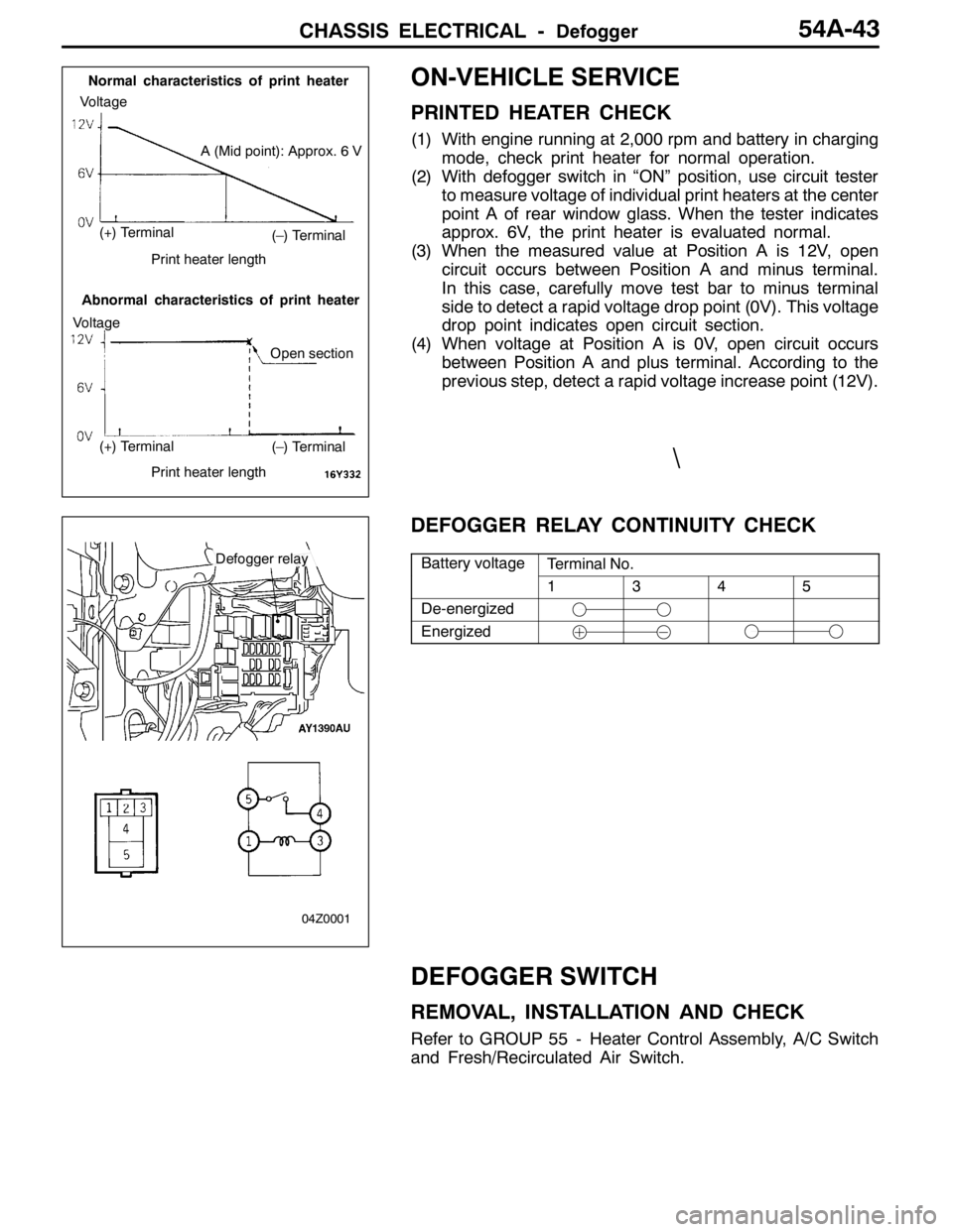
CHASSIS ELECTRICAL -Defogger54A-43
ON-VEHICLE SERVICE
PRINTED HEATER CHECK
(1) With engine running at 2,000 rpm and battery in charging
mode, check print heater for normal operation.
(2) With defogger switch in “ON” position, use circuit tester
to measure voltage of individual print heaters at the center
point A of rear window glass. When the tester indicates
approx. 6V, the print heater is evaluated normal.
(3) When the measured value at Position A is 12V, open
circuit occurs between Position A and minus terminal.
In this case, carefully move test bar to minus terminal
side to detect a rapid voltage drop point (0V). This voltage
drop point indicates open circuit section.
(4) When voltage at Position A is 0V, open circuit occurs
between Position A and plus terminal. According to the
previous step, detect a rapid voltage increase point (12V).
DEFOGGER RELAY CONTINUITY CHECK
Battery voltageTerminal No.yg
1345
De-energized
Energized
DEFOGGER SWITCH
REMOVAL, INSTALLATION AND CHECK
Refer to GROUP 55 - Heater Control Assembly, A/C Switch
and Fresh/Recirculated Air Switch.
(–) Terminal
(–) Terminal
A (Mid point): Approx. 6 V
Normal characteristics of print heater
Abnormal characteristics of print heater
Voltage
Voltage
(+) Terminal
(+) Terminal
Print heater length
Print heater length
Open section
Defogger relay
04Z0001
\