Page 1443 of 1449
CondenserAssemblyand
Condenser Fan Assembly HEATER, AIR CONDITIONER AND VENTILATION-55-41
AB"FLEXIBLE DISCHARGE HOSE AND LIQUID PIPE
A DISCONNECTION
To prevent the entry of dust or other foreign objects, plug
the dismantled hose and condenser assembly nipples.
Caution
As the compressor oil and receiver are highly moisture
absorbent, use a non - porous material to plug the hose
and nipples.
INSPECTION
CONDENSER FAN CHECK
Battery connection terminalCondenser fan
Connector AConnector B
1212
LO rotation
HI rotation
Connector A
Connector B
Page 1444 of 1449

HEATER, AIR CONDITIONER AND VENTILATION-Refrigerant Lines55-42
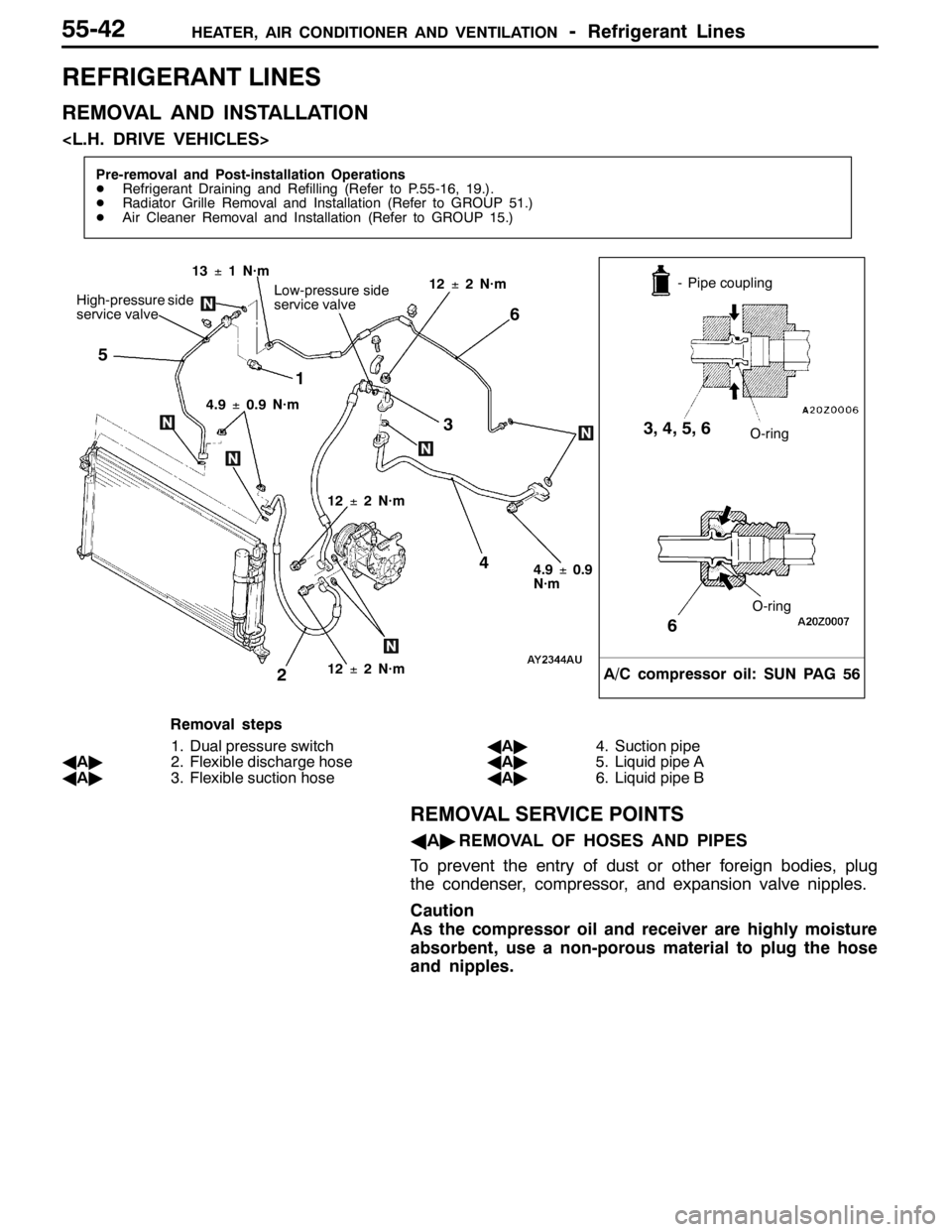
REFRIGERANT LINES
REMOVAL AND INSTALLATION
Pre-removal and Post-installation Operations
DRefrigerant Draining and Refilling (Refer to P.55-16, 19.).
DRadiator Grille Removal and Installation (Refer to GROUP 51.)
DAir Cleaner Removal and Installation (Refer to GROUP 15.)
1
2
- Pipe coupling
O-ring
A/C compressor oil: SUN PAG 56
3, 4, 5, 6
5
4
13±1 N·m
O-ring
6
12±2 N·m4.9±0.9
N·m
High-pressure side
service valve
4.9±0.9 N·m6
3
12±2 N·m
Low-pressure side
service valve12±2 N·m
Removal steps
1. Dual pressure switch
AA"2. Flexible discharge hose
AA"3. Flexible suction hoseAA"4. Suction pipe
AA"5. Liquid pipe A
AA"6. Liquid pipe B
REMOVAL SERVICE POINTS
AA"REMOVAL OF HOSES AND PIPES
To prevent the entry of dust or other foreign bodies, plug
the condenser, compressor, and expansion valve nipples.
Caution
As the compressor oil and receiver are highly moisture
absorbent, use a non-porous material to plug the hose
and nipples.
Page 1445 of 1449
HEATER, AIR CONDITIONER AND VENTILATION-Refrigerant Lines55-43
REMOVAL AND INSTALLATION
Pre-removal and Post-installation Operations
DRefrigerant Draining and Refilling (Refer to P.55-16, 19.)
DRadiator Grille Removal and Installation (Refer to GROUP 51.)
DAir Cleaner Removal and Installation (Refer to GROUP 15.)
1
23
- Pipe
coupling
O ring
A/C compressor oil: SUN PAG 56
2, 3, 4, 5, 6
6
513±1 N·m
Low - pressure side
service valve
O ring
6
12±2 N·m 4.9±0.9 N·m
High - pressure side
service valve
4.9±0.9
N·m
4
12±2 N·m
12±2 N·m
Removal steps
1. Dual pressure switch
AA"2. Flexible discharge hose
AA"3. Flexible suction hoseAA"4. Suction pipe
AA"5. Liquid pipe A
AA"6. Liquid pipe B
REMOVAL SERVICE POINTS
AA"REMOVAL OF HOSES AND PIPES
To prevent the entry of dust or other foreign bodies, plug
the condenser, compressor, and expansion valve nipples.
Caution
As the compressor oil and receiver are highly moisture
absorbent, use a non-porous material to plug the hose
and nipples.
Page 1446 of 1449
HEATER, AIR CONDITIONER AND VENTILATION-Ducts55-44
DUCTS
REMOVAL AND INSTALLATION
4
3 5 4
8
76
1 2 3
A
A
Cross-section A - A
Clip
Instrument panel
1
Air outlet removal steps
1. Center air outlet panel
2. Center air outlet
3. Side air outlet
Defroster nozzle and distribution
duct removal steps
DInstrument panel (Refer to GROUP
52A.)
4. Side defroster duct5. Defroster nozzle
6. Distribution duct
Foot duct removal step
DConsole cover and glove box (Refer
to GROUP 52A – Instrument Panel.)
7. Right-hand foot duct
DUnder cover (Refer to GROUP 52A
– Instrument Panel.)
8. Left-hand foot duct
Page 1447 of 1449
HEATER, AIR CONDITIONER AND VENTILATION-Ventilation55-45
VENTILATION
REMOVAL AND INSTALLATION
Pre-removal and Post-installation Operations
Rear Bumper Removal and Installation (Refer to
GROUP 51.)
A
BClaw
Claw
Cross-section A - A
Cross-section B - B
A
A
11 1
A
B
1. Rear ventilation duct
RJAK104003 - 1094