2007 MITSUBISHI LANCER EVOLUTION heater
[x] Cancel search: heaterPage 436 of 1449

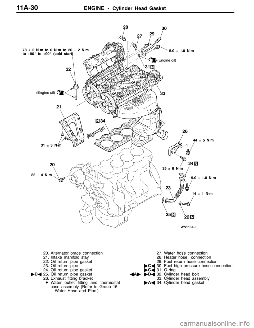
ENGINE -Cylinder Head Gasket11A-30
23 31
24 26 27 28
2930
22
22±4 N·m5.0±1.0 N·m
31±3 N·m
(Engine oil)
2021
25
9.0±1.0 N·m
14±1 N·m
33 32
(Engine oil)
78±2 N·m to 0 N·m to 20±2 N·m
to +90_to +90_(cold start)
35±6 N·m44±5 N·m
34
20. Alternator brace connection
21. Intake manifold stay
22. Oil return pipe gasket
23. Oil return pipe
24. Oil return pipe gasket
"DA25. Oil return pipe gasket
26. Exhaust fitting bracket
DWater outlet fitting and thermostat
case assembly (Refer to Group 15
- Water Hose and Pipe.)27. Water hose connection
28. Heater hose connection
29. Fuel return hose connection
"CA30. Fuel high pressure hose connection
"CA31. O-ring
AA""BA32. Cylinder head bolt
33. Cylinder head assembly
"AA34. Cylinder head gasket
Page 451 of 1449

ENGINE -Engine Assembly11A-45
67±7 N·m*
23 33
24 29
3031
32
2722
98±10 N·m*5.0±1.0 N·m
(Engine oil)
20
21 19
25
42±2 N·m22±4 N·m
40±5 N·m
42±2 N·m
26
26
2834
22±4 N·m12±2 N·m
19. Brake booster vacuum hose
connection
20. Purge hose connection
21. Power steering oil pressure switch
connector
22. Heat protector
AB"23. Power steering oil pump, bracket and
oil reservoir assembly
24. A/C compressor connector
AB"25. A/C compressor
26. Engine oil cooler tube gasket
27. Engine oil cooler feed hose connection28. Engine oil cooler return hose
connection
29. Heater hose connection
30. Fuel return hose connection
"CA31. Fuel high pressure hose connection
"CA32. O-ring
DTransfer assembly
(Refer to Group 22.)
DTransmission assembly
(Refer to Group 22.)
AC""BA33. Engine mounting bracket and stopper
assembly
AD""AA34. Engine assembly
Page 538 of 1449

MPI -Service Specifications/Sealant13A-6
SERVICE SPECIFICATIONS
ItemsSpecifications
Basic idle speed r/min850±100
Throttle position sensor adjusting voltage mV535 - 735
Throttle position sensor resistance kΩ3.5 - 6.5
Idle speed control servo coil resistance (at 20_C)Ω28 - 33
Intake air temperature sensor
resistancekΩ
-20_C13 - 17
resistance kΩ0_C5.7 - 6.7
20_C2.3 - 3.0
40_C1.0 - 1.5
60_C0.56 - 0.76
80_C0.30 - 0.42
Engine coolant temperature
sensorresistancekΩ
-20_C14 - 17
sensor resistance kΩ0_C5.1 - 6.5
20_C2.1 - 2.7
40_C0.9 - 1.3
60_C0.48 - 0.68
80_C0.26 - 0.36
Oxygen sensor heater
resistance(at20_C)Ω
Front4.5 - 8.0
resistance (at 20_C)ΩRear11 - 1 8
Oxygen sensor output voltage (at racing) V0.6 - 1.0
Fuel pressure kPaVacuum hose disconnection289 - 309 at curb idle
Vacuum hose connectionApproximately 230 at curb idle
Fuel pressure control solenoid valve resistance (at 20_C)Ω28 - 36
Fuel pump resistor resistanceΩ0.45 - 0.65
Injector coil resistance (at 20_C)Ω2-3
Injector fuel leakage rate Drop/minute1 or less
Resistor (for injector) resistance (at 20_C)Ω5.8 - 6.2
SEALANT
ItemSpecified sealantRemark
Engine coolant temperature sensor
threaded portion3M Nut Locking Part No. 4171 or equivalentDrying sealant
Page 541 of 1449

MPI -Troubleshooting13A-9
TROUBLESHOOTING
DIAGNOSIS TROUBLESHOOTING FLOW
Refer to GROUP 00 - How to Use Troubleshooting/Inspection
Service Point.
NOTE
If the engine-ECU is replaced, the immobilizer-ECU and
ignition key should be replaced together with it.
DIAGNOSIS FUNCTION
ENGINE WARNING LAMP (CHECK ENGINE LAMP)
If an abnormality occurs in any of the following items related
to the MPI system, the engine warning lamp will illuminate
or flash. If the lamp remains illuminated or if the lamp
illuminates while the engine is running, check the diagnosis
code output.
However, the warning lamp will illuminate as bulb check for
5 seconds whenever the ignition switch is turned to the ON
position.
Engine warning lamp inspection items
Code No.Diagnosis item
-Engine-ECU
P0100Air flow sensor system
P0105Barometric pressure sensor system
P0110Intake air temprature sensor system
P0115Engine coolant temperature sensor system
P0120Throttle position sensor system
P0130Oxygen sensor (front) system
P0135Oxygen sensor heater (front) system
P0136Oxygen sensor (rear) system
P0141Oxygen sensor heater (rear) system
P0201No.1 injector system
P0202No.2 injector system
P0203No.3 injector system
P0204No.4 injector system
P0325Detonation sensor system
P0335Crank angle sensor system
P0340Camshaft position sensor system
P0403EGR control solenoid valve system
Engine warning lamp
(check engine lamp)
Page 544 of 1449

MPI -Troubleshooting13A-12
INSPECTION CHART FOR DIAGNOSIS CODES
Code No.Diagnosis itemReference page
P0100Air flow sensor system13A-13
P0105Barometric pressure sensor system13A-15
P0110Intake air temprature sensor system13A-16
P0115Engine coolant temperature sensor system13A-19
P0120Throttle position sensor system13A-21
P0130Oxygen sensor (front) system13A-24
P0135Oxygen sensor heater (front) system13A-26
P0136Oxygen sensor (rear) system13A-27
P0141Oxygen sensor heater (rear) system13A-29
P0201No.1 injector system13A-30
P0202No.2 injector system13A-31
P0203No.3 injector system13A-32
P0204No.4 injector system13A-33
P0325Detonation sensor system13A-34
P0335Crank angle sensor system13A-35
P0340Camshaft position sensor system13A-37
P0403EGR control solenoid valve system13A-39
P0443Purge control solenoid valve system13A-41
P0500Vehicle speed sensor system13A-43
P0505Idle speed control system13A-44
P0551Power steering fluid pressure switch system13A-46
P1104Waste gate solenoid valve system13A-47
P1105Fuel pressure control valve system13A-48
P1500Alternator FR terminal system13A-49
P1603Battery backup line malfunction13A-50
P1610Immobilizer system13A-51
Page 558 of 1449

MPI -Troubleshooting13A-26
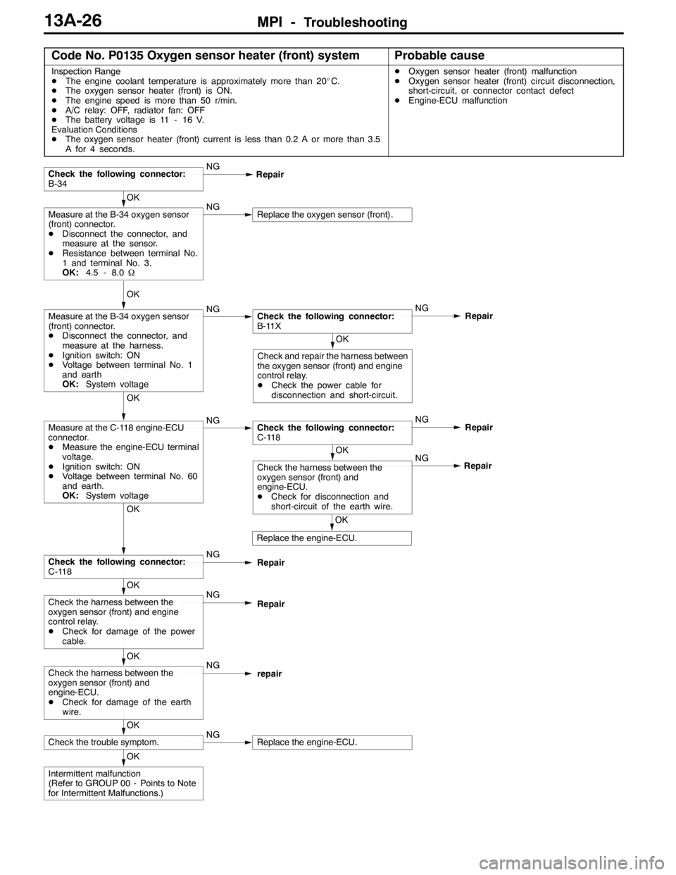
Code No. P0135 Oxygen sensor heater (front) systemProbable cause
Inspection Range
DThe engine coolant temperature is approximately more than 20_C.
DThe oxygen sensor heater (front) is ON.
DThe engine speed is more than 50 r/min.
DA/C relay: OFF, radiator fan: OFF
DThe battery voltage is 11 - 16 V.
Evaluation Conditions
DThe oxygen sensor heater (front) current is less than 0.2 A or more than 3.5
A for 4 seconds.DOxygen sensor heater (front) malfunction
DOxygen sensor heater (front) circuit disconnection,
short-circuit, or connector contact defect
DEngine-ECU malfunction
OK
Intermittent malfunction
(Refer to GROUP 00 - Points to Note
for Intermittent Malfunctions.)
OK
Check the trouble symptom.NGReplace the engine-ECU.
OK
Check the harness between the
oxygen sensor (front) and
engine-ECU.
DCheck for damage of the earth
wire.NG
repair
OK
Check the harness between the
oxygen sensor (front) and engine
control relay.
DCheck for damage of the power
cable.NG
Repair
OK
Check the following connector:
C-118NG
Repair
OK
Replace the engine-ECU.NG
OK
Check the harness between the
oxygen sensor (front) and
engine-ECU.
DCheck for disconnection and
short-circuit of the earth wire.Repair
OK
Measure at the C-118 engine-ECU
connector.
DMeasure the engine-ECU terminal
voltage.
DIgnition switch: ON
DVoltage between terminal No. 60
and earth.
OK:System voltageNGCheck the following connector:
C-118NG
Repair
OK
Check and repair the harness between
the oxygen sensor (front) and engine
control relay.
DCheck the power cable for
disconnection and short-circuit.
OK
Measure at the B-34 oxygen sensor
(front) connector.
DDisconnect the connector, and
measure at the harness.
DIgnition switch: ON
DVoltage between terminal No. 1
and earth
OK:System voltageNGCheck the following connector:
B-11XNG
Repair
OK
Measure at the B-34 oxygen sensor
(front) connector.
DDisconnect the connector, and
measure at the sensor.
DResistance between terminal No.
1 and terminal No. 3.
OK:4.5 - 8.0ΩNGReplace the oxygen sensor (front).
Check the following connector:
B-34NG
Repair
Page 561 of 1449

MPI -Troubleshooting13A-29
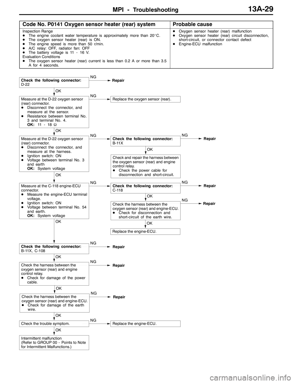
Code No. P0141 Oxygen sensor heater (rear) systemProbable cause
Inspection Range
DThe engine coolant water temperature is approximately more than 20_C.
DThe oxygen sensor heater (rear) is ON.
DThe engine speed is more than 50 r/min.
DA/C relay: OFF, radiator fan: OFF
DThe battery voltage is 11 - 16 V.
Evaluation Conditions
DThe oxygen sensor heater (rear) current is less than 0.2 A or more than 3.5
A for 4 seconds.DOxygen sensor heater (rear) malfunction
DOxygen sensor heater (rear) circuit disconnection,
short-circuit, or connector contact defect
DEngine-ECU malfunction
OK
Intermittent malfunction
(Refer to GROUP 00 - Points to Note
for Intermittent Malfunctions.)
OK
Check the trouble symptom.NGReplace the engine-ECU.
OK
Check the harness between the
oxygen sensor (rear) and engine-ECU.
DCheck for damage of the earth
wire.NG
Repair
OK
Check the harness between the
oxygen sensor (rear) and engine
control relay.
DCheck for damage of the power
cable.NG
Repair
OK
Check the following connector:
B-11X, C-108NG
Repair
OK
Replace the engine-ECU.NG
OK
Check the harness between the
oxygen sensor (rear) and engine-ECU.
DCheck for disconnection and
short-circuit of the earth wire.Repair
OK
Measure at the C-118 engine-ECU
connector.
DMeasure the engine-ECU terminal
voltage.
DIgnition switch: ON
DVoltage between terminal No. 54
and earth.
OK:System voltageNGCheck the following connector:
C-118NG
Repair
OK
Check and repair the harness between
the oxygen sensor (rear) and engine
control relay.
DCheck the power cable for
disconnection and short-circuit.
OK
Measure at the D-22 oxygen sensor
(rear) connector.
DDisconnect the connector, and
measure at the harness.
DIgnition switch: ON
DVoltage between terminal No. 3
and earth
OK:System voltageNGCheck the following connector:
B-11XNG
Repair
OK
Measure at the D-22 oxygen sensor
(rear) connector.
DDisconnect the connector, and
measure at the sensor.
DResistance between terminal No.
3 and terminal No. 4.
OK:11 - 1 8ΩNGReplace the oxygen sensor (rear).
Check the following connector:
D-22NG
Repair
Page 643 of 1449

MPI -Troubleshooting13A-111
Terminal No.Normal condition Check condition (Engine condition) Check item
37Power steering fluid
pressure switchEngine: Idling after
warming upWhen steering wheel
is stationarySystem voltage
When steering wheel
is turned1 V or less
38Engine control relayIgnition switch: “LOCK” (OFF)System voltage
Ignition switch: “ON”1 V or less
39Fuel pump relay 3While engine is idling, suddenly depress the
accelerator pedal.Temporarily rises slightly
from 1 V or less.
41Alternator FR
terminalDEngine: After warm-up, idle operation
DRadiator fan: Not operating
DHead lamp: OFF→ON
DStop lamp: OFF→ON
DRear deffogger switch: OFF→ONVoltage decrease
44Intercooler water
spray switch (Auto)DIgnition switch: “ON”
DIntercooler water spray switch: ON1 V or less
DIgnition switch: “ON”
DIntercooler water spray switch: OFFSystem voltage
45A/C switchEngine: Idle operationTurn the A/C switch
OFF0.5 V or less
DA/C switch: ON
DA/C setting
temperature
When room tem-
perature is 25_C
or more: Max
Cool
When room tem-
perature is 25_C
or less: Max. HotSystem voltage
53Secondary air control
solenoid valveIgnition switch: “ON”System voltage
54Oxygen sensor
heater(Rear)
Engine: Idling after warming up1 V or less
heater(Rear)
Engine speed: 5,000r/minSystem voltage
55Intercooler water
sprayrelay
Ignition switch: “ON”System voltage
spray relay
Ignition switch: “LOCK” (OFF)1 V or less
58Tachometer signalEngine speed: 3,000r/min0.3 - 3.0 V
60Oxygen sensor
heater(front)
Engine: Idling after warming up1 V or less
heater(front)
Engine speed: 5,000r/minSystem voltage
71Ignition switch - STEngine: Cranking8 V or more