Page 1390 of 1449
SWS -Troubleshooting54B-26
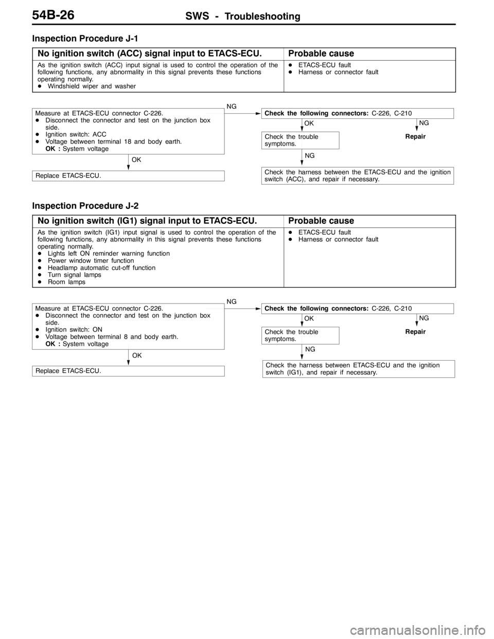
Inspection Procedure J-1
No ignition switch (ACC) signal input to ETACS-ECU.
Probable cause
As the ignition switch (ACC) input signal is used to control the operation of the
following functions, any abnormality in this signal prevents these functions
operating normally.
DWindshield wiper and washerDETACS-ECU fault
DHarness or connector fault
NG
Repair
NG
Check the harness between the ETACS-ECU and the ignition
switch (ACC), and repair if necessary.
OK
Replace ETACS-ECU.
OK
Check the trouble
symptoms.
Measure at ETACS-ECU connector C-226.
DDisconnect the connector and test on the junction box
side.
DIgnition switch: ACC
DVoltage between terminal 18 and body earth.
OK :System voltageNGCheck the following connectors:C-226, C-210
Inspection Procedure J-2
No ignition switch (IG1) signal input to ETACS-ECU.
Probable cause
As the ignition switch (IG1) input signal is used to control the operation of the
following functions, any abnormality in this signal prevents these functions
operating normally.
DLights left ON reminder warning function
DPower window timer function
DHeadlamp automatic cut-off function
DTurn signal lamps
DRoom lampsDETACS-ECU fault
DHarness or connector fault
NG
Repair
NG
Check the harness between ETACS-ECU and the ignition
switch (IG1), and repair if necessary.
OK
Replace ETACS-ECU.
OK
Check the trouble
symptoms.
Measure at ETACS-ECU connector C-226.
DDisconnect the connector and test on the junction box
side.
DIgnition switch: ON
DVoltage between terminal 8 and body earth.
OK :System voltageNGCheck the following connectors:C-226, C-210
Page 1391 of 1449
SWS -Troubleshooting54B-27
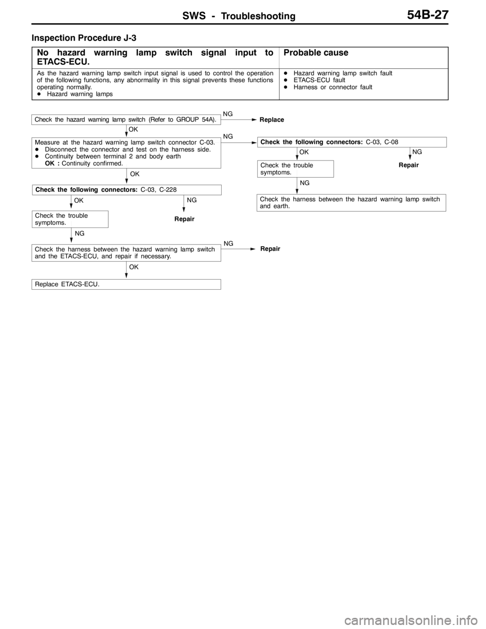
Inspection Procedure J-3
No hazard warning lamp switch signal input to
ETACS-ECU.
Probable cause
As the hazard warning lamp switch input signal is used to control the operation
of the following functions, any abnormality in this signal prevents these functions
operating normally.
DHazard warning lampsDHazard warning lamp switch fault
DETACS-ECU fault
DHarness or connector fault
NG
Repair
NG
Check the harness between the hazard warning lamp switch
and earth.NG
Repair
OK
Replace ETACS-ECU.
NG
Check the harness between the hazard warning lamp switch
and the ETACS-ECU, and repair if necessary.NG
Repair
OK
Check the trouble
symptoms.
OK
Check the following connectors:C-03, C-228
OK
Check the trouble
symptoms.
OK
Measure at the hazard warning lamp switch connector C-03.
DDisconnect the connector and test on the harness side.
DContinuity between terminal 2 and body earth
OK :Continuity confirmed.NGCheck the following connectors:C-03, C-08
Check the hazard warning lamp switch (Refer to GROUP 54A).NG
Replace
Page 1392 of 1449
SWS -Troubleshooting54B-28
Inspection Procedure J-4
No fog lamp switch signal input to ETACS-ECU.
Probable cause
When the rear fog lamp switch input signal fault occurs, the rear fog lamp
switch signal is not transmitted to the SWS communication line.DRear fog lamp switch inoperative
DETACS-ECU fault
DHarness or connector fault
NG
RepairOK
Check and repair the harness from the rear fog lamp switch
to the body earth.
NG
Replace ETACS-ECU.
OK
OK
Check the harness from the rear fog lamp switch to
ETACS-ECU.NG
Repair
OK
Check the following connectors:C-137, C-227NG
Repair
OK
Measure at the rear fog lamp switch connector C-137.
DDisconnect the connector and test on the harness side.
DContinuity between terminal 6 and body earth
OK :Continuity confirmed.NGCheck the following connectors:
C-137, C-102
C-137, C-08
Check the rear fog lamp switch (Refer to GROUP 54A - Rear
Fog Lamp).NG
Replace
Check the trouble symptoms.
Page 1393 of 1449
SWS -Troubleshooting54B-29
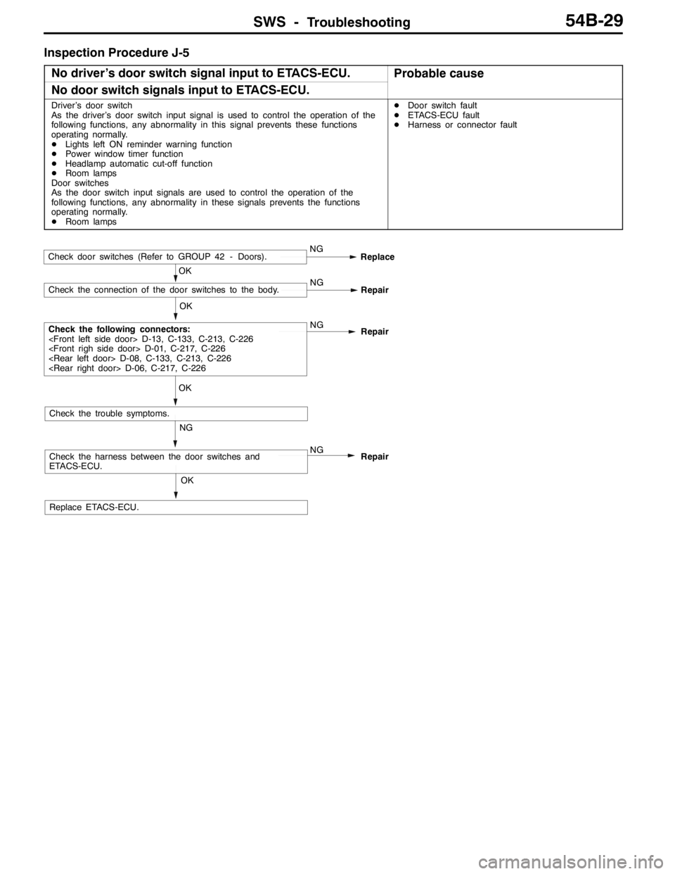
Inspection Procedure J-5
No driver’s door switch signal input to ETACS-ECU.
Probable cause
No door switch signals input to ETACS-ECU.
Driver’s door switch
As the driver’s door switch input signal is used to control the operation of the
following functions, any abnormality in this signal prevents these functions
operating normally.
DLights left ON reminder warning function
DPower window timer function
DHeadlamp automatic cut-off function
DRoom lamps
Door switches
As the door switch input signals are used to control the operation of the
following functions, any abnormality in these signals prevents the functions
operating normally.
DRoom lampsDDoor switch fault
DETACS-ECU fault
DHarness or connector fault
OK
Replace ETACS-ECU.
NG
Check the harness between the door switches and
ETACS-ECU.NG
Repair
OK
Check the trouble symptoms.
OK
Check the following connectors:
D-13, C-133, C-213, C-226
D-01, C-217, C-226
D-08, C-133, C-213, C-226
D-06, C-217, C-226NG
Repair
OK
Check the connection of the door switches to the body.NG
Repair
Check door switches (Refer to GROUP 42 - Doors).NG
Replace
Page 1394 of 1449
SWS -Troubleshooting54B-30
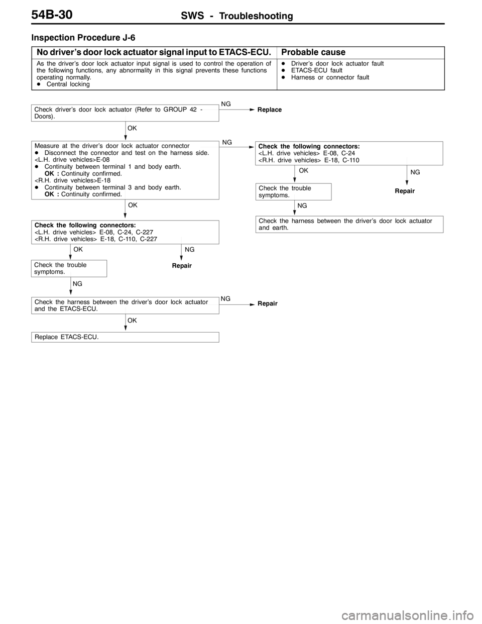
Inspection Procedure J-6
No driver’s door lock actuator signal input to ETACS-ECU.
Probable cause
As the driver’s door lock actuator input signal is used to control the operation of
the following functions, any abnormality in this signal prevents these functions
operating normally.
DCentral lockingDDriver’s door lock actuator fault
DETACS-ECU fault
DHarness or connector fault
NG
Repair
NG
Check the harness between the driver’s door lock actuator
and earth.
NG
Repair
OK
Replace ETACS-ECU.
NG
Check the harness between the driver’s door lock actuator
and the ETACS-ECU.NG
Repair
OK
Check the trouble
symptoms.
OK
Check the following connectors:
E-08, C-24, C-227
E-18, C-110, C-227
OK
Check the trouble
symptoms.
OK
Measure at the driver’s door lock actuator connector
DDisconnect the connector and test on the harness side.
E-08
DContinuity between terminal 1 and body earth.
OK :Continuity confirmed.
E-18
DContinuity between terminal 3 and body earth.
OK :Continuity confirmed.NGCheck the following connectors:
E-08, C-24
E-18, C-110
Check driver’s door lock actuator (Refer to GROUP 42 -
Doors).NG
Replace
Page 1396 of 1449
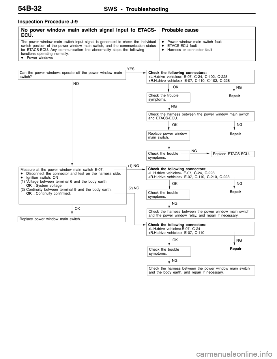
SWS -Troubleshooting54B-32
Inspection Procedure J-9
No power window main switch signal input to ETACS-
ECU.
Probable cause
The power window main switch input signal is generated to check the individual
switch position of the power window main switch, and the communication status
for ETACS-ECU. Any communication line abnormality stops the following
functions operating normally.
DPower windowsDPower window main switch fault
DETACS-ECU fault
DHarness or connector fault
Check the trouble
symptoms.NGReplace ETACS-ECU.
NG
Repair
NG
Repair
OK
Replace power window
main switch.
NG
Repair
NG
Check the harness between the power window main switch
and the power window relay, and repair if necessary.
NG
Repair
NG
Check the harness between the power window main switch
and the body earth, and repair if necessary.
OK
Replace power window main switch.
OK
Check the trouble
symptoms.
(2) NG
Check the following connectors:
E-07, C-24
E-07, C-110
OK
Check the trouble
symptoms.
NO
Measure at the power window main switch E-07.
DDisconnect the connector and test on the harness side.
DIgnition switch: ON
(1) Voltage between terminal 6 and the body earth.
OK :System voltage
(2) Continuity between terminal 9 and the body earth.
OK :Continuity confirmed.(1) NGCheck the following connectors:
E-07, C-24, C-228
E-07, C-110, C-210, C-228
NG
Check the harness between the power window main switch
and ETACS-ECU.
OK
Check the trouble
symptoms.
Can the power windows operate off the power window main
switch?YESCheck the following connectors:
E-07, C-24, C-102, C-228
E-07, C-110, C-102, C-228
Page 1397 of 1449
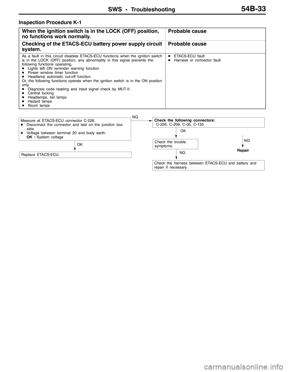
SWS -Troubleshooting54B-33
Inspection Procedure K-1
When the ignition switch is in the LOCK (OFF) position,
no functions work normally.
Probable cause
Checking of the ETACS-ECU battery power supply circuit
system.Probable cause
As a fault in this circuit disables ETACS-ECU functions when the ignition switch
is in the LOCK (OFF) position, any abnormality in this signal prevents the
following functions operating.
DLights left ON reminder warning function
DPower window timer function
DHeadlamp automatic cut-off function
Or, the following functions operate when the ignition switch is in the ON position
only.
DDiagnosis code reading and input signal check by MUT-II.
DCentral locking
DHeadlamps, tail lamps
DHazard lamps
DRoom lampsDETACS-ECU fault
DHarness or connector fault
NG
RepairNG
Check the harness between ETACS-ECU and battery and
repair if necessary.
OK
Replace ETACS-ECU.
OK
Check the trouble
symptoms.
Measure at ETACS-ECU connector C-226.
DDisconnect the connector and test on the junction box
side.
DVoltage between terminal 20 and body earth.
OK :System voltageNGCheck the following connectors:
C-226, C-209, C-05, C-135
Page 1403 of 1449

55-1
HEATER, AIR
CONDITIONER AND
VENTILATION
CONTENTS
SERVICE SPECIFICATIONS 2.................
LUBRICANTS 2..............................
SPECIAL TOOLS 2...........................
TROUBLESHOOTING 3.......................
ON-VEHICLE SERVICE 14....................
Refrigerant Level Test through Performance Test 14.
Magnetic Clutch Test 14.........................
Receiver Drier Test 14..........................
Compressor Drive Belt Adjustment 15.............
Dual Pressure Switch Check 15..................
Charging 16...................................
Correcting Low Refrigerant Level in case the Service
can used 18...................................
Discharging System 19..........................
Refilling of Oil in the A/C System 19...............
Performance Test 20............................
Refrigerant Leak Repair 21......................
Blower Relay Continuity Check 22................
A/C Compressor Relay Continuity Check 22........Condenser Fan Relay (LO) Check 23.............
Condenser Fan Relay (HI) Check 23..............
Idle-up Operation Check 24.....................
HEATER CONTROL ASSEMBLY (A/C-ECU)
AND A/C SWITCH 25........................
HEATER UNIT AND BLOWER ASSEMBLY 28.
REGISTOR, BLOWER MOTOR AND
INSIDE/OUTSIDE AIR CHANGE OVER
DAMPER MOTOR 32.........................
EVAPORATOR AND AIR THERMO SENSOR
34 ...........................................
COMPRESSOR 36............................
CONDENSER ASSEMBLY AND CONDENSER
FAN ASSEMBLY 40...........................
REFRIGERANT LINES 42.....................
DUCTS 44...................................
VENTILATION 45.............................