Page 1305 of 1449

SRS -Seat Belt with Pre-tensioner52B-61
SEAT BELT WITH PRE-TENSIONER
Caution:
1. Wait for at least 60 seconds after
disconnecting the negative ( - ) terminal of
the battery before starting any operation.The
removed negative ( - ) terminal must be
protected by wrapping the tape. (Refer to
P.52B-3.)
2. Never disassemble or repair the seat belt
with pre-tensioner. Replace the part with a
new one when it malfunctions.
3. Take an extra care to deal with the seat belt
with pre-tensioner by avoiding dropping or
wetting it with water or oil. If any dent, crack,
or deformation is found, be sure to replace
the seat belt with pre-tensioner with a new
part.4. Do not place a heavy object on top of the
seat belt pre-tensioner.
5. Never keep the seat belt with pre-tensioner
in a place where the temperature can exceed
over 90_C.
6. Replace the seat belt with pre-tensioner with
a new one after operating the seat belt
pre-tensioner.
7. Wear gloves or protective glasses when
handling the seat belt with pre-tensioner
after operation.
8. If the seat belt with pre-tensioner before
operation needs to be discarded, be sure
to do so after operating the seat belt
pre-tensioner. (Refer to P.52B-64.)
REMOVAL AND INSTALLATION
Pre - removal operation
DTurn the ignition key to the LOCK(OFF) position.
DDisconnect the negative ( - ) terminal of the battery.
1 4
3
2
44±10 NSm
44±10 NSm
5
Removal steps
1. Sash cover guide
2. Seat belt lower anchor bolt
3. Bracket
4. Seat belt shoulder anchor bolt
DCenter pillar lower trim
(Refer to GROUP 52A - Trim.)
5. Seat belt pre-tensionerInstallation steps
"AA
DPre - installation inspection
5. Seat belt pre-tensioner
4. Seat belt shoulder anchor bolt
3. Bracket
2. Seat belt lower anchor bolt
DCenter pillar lower trim
(Refer to GROUP 52A - Trim.)
1. Sash cover guide
DNegative ( - ) terminal of the battery
connection
"BADPost - installation inspection
Page 1328 of 1449
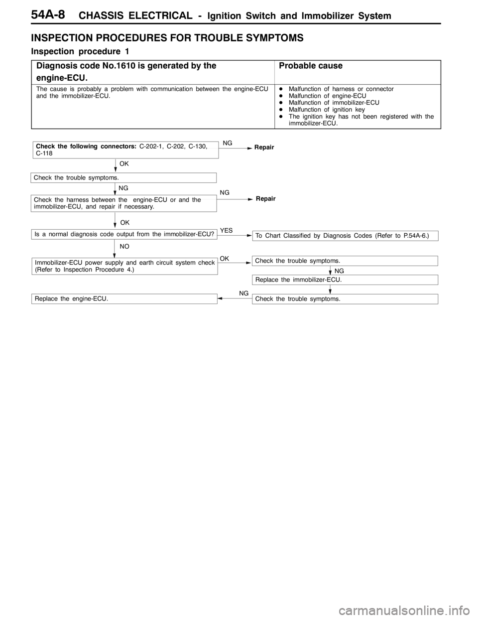
CHASSIS ELECTRICAL -Ignition Switch and Immobilizer System54A-8
INSPECTION PROCEDURES FOR TROUBLE SYMPTOMS
Inspection procedure 1
Diagnosis code No.1610 is generated by the
engine-ECU.
Probable cause
The cause is probably a problem with communication between the engine-ECU
and the immobilizer-ECU.DMalfunction of harness or connector
DMalfunction of engine-ECU
DMalfunction of immobilizer-ECU
DMalfunction of ignition key
DThe ignition key has not been registered with the
immobilizer-ECU.
OKImmobilizer-ECU power supply and earth circuit system check
(Refer to Inspection Procedure 4.)
OK
Check the trouble symptoms.
NGRepair
NGCheck the following connectors:C-202-1, C-202, C-130,
C-118
Repair
NGCheck the harness between the engine-ECU or and the
immobilizer-ECU, and repair if necessary.
NG
Replace the immobilizer-ECU.
Check the trouble symptoms.
Check the trouble symptoms.Replace the engine-ECU.OK
Is a normal diagnosis code output from the immobilizer-ECU?
NOTo Chart Classified by Diagnosis Codes (Refer to P.54A-6.) YES
NG
Page 1330 of 1449
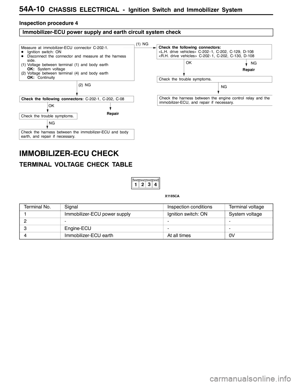
CHASSIS ELECTRICAL -Ignition Switch and Immobilizer System54A-10
Inspection procedure 4
Immobilizer-ECU power supply and earth circuit system check
NG
Check the harness between the engine control relay and the
immobilizer-ECU, and repair if necessary.
OK
Check the trouble symptoms.
(2) NG
Repair
Measure at immobilizer-ECU connector C-202-1.
DIgnition switch: ON
DDisconnect the connector and measure at the harness
side.
(1) Voltage between terminal (1) and body earth
OK:System voltage
(2) Voltage between terminal (4) and body earth
OK:Continuity(1) NGCheck the following connectors:
C-202 - 1, C-202, C-129, D-108
C-202 - 1, C-202, C-130, D-108
NG
NG
OK
Check the trouble symptoms.Repair
NG
Check the following connectors:C-202-1, C-202, C-08
Check the harness between the immobilizer-ECU and body
earth, and repair if necessary.
IMMOBILIZER-ECU CHECK
TERMINAL VOLTAGE CHECK TABLE
Terminal No.SignalInspection conditionsTerminal voltage
1Immobilizer-ECU power supplyIgnition switch: ONSystem voltage
2---
3Engine-ECU--
4Immobilizer-ECU earthAt all times0V
Page 1336 of 1449
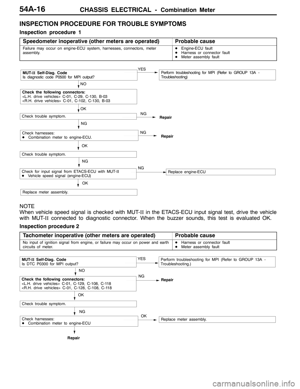
CHASSIS ELECTRICAL -Combination Meter54A-16
INSPECTION PROCEDURE FOR TROUBLE SYMPTOMS
Inspection procedure 1
Speedometer inoperative (other meters are operated)
Probable cause
Failure may occur on engine-ECU system, harnesses, connectors, meter
assembly.DEngine-ECU fault
DHarness or connector fault
DMeter assembly fault
NO
MUT-IISelf-Diag. Code
Is diagnostic code P0500 for MPI output?YESPerform troubleshooting for MPI (Refer to GROUP 13A -
Troubleshooting)
OK
NG
Check the following connectors:
C-01, C-29, C-130, B-03
C-01, C-102, C-130, B-03
Repair
OK
Check trouble symptom.
NG
NG
RepairCheck harnesses:
DCombination meter to engine-ECU.
Check trouble symptom.
NG
Replace meter assembly.
OK
Check for input signal from ETACS-ECU with MUT-II
DVehicle speed signal (engine-ECU)NGReplace engine-ECU
NOTE
When vehicle speed signal is checked with MUT-IIin the ETACS-ECU input signal test, drive the vehicle
with MUT-IIconnected to diagnostic connector. When the buzzer sounds, this test is evaluated OK.
Inspection procedure 2
Tachometer inoperative (other meters are operated)
Probable cause
No input of ignition signal from engine, or failure may occur on power and earth
circuits of meter.DHarness or connector fault
DMeter assembly fault
OK
NO
MUT-IISelf-Diag. Code
Is DTC P0300 for MPI output?YESPerform troubleshooting for MPI (Refer to GROUP 13A -
Troubleshooting.)
NG
NG
RepairRepair
Check trouble symptom.
OK
Check the following connectors:
C-01, C-129, C-108, C-118
C-01, C-128, C-108, C-118
Replace meter assembly.Check harnesses:
DCombination meter to engine-ECU
Page 1337 of 1449
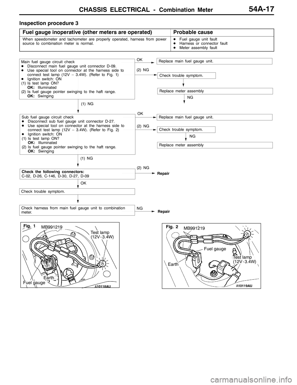
CHASSIS ELECTRICAL -Combination Meter54A-17
Inspection procedure 3
Fuel gauge inoperative (other meters are operated)
Probable cause
When speedometer and tachometer are properly operated, harness from power
source to combination meter is normal.DFuel gauge unit fault
DHarness or connector fault
DMeter assembly fault
OKReplace main fuel gauge unit.
NG
Check harness from main fuel gauge unit to combination
meter.Repair
Check trouble symptom.
Main fuel gauge circuit check
DDisconnect main fuel gauge unit connector D-09.
DUse special tool on connector at the harness side to
connect test lamp (12V – 3.4W). (Refer to Fig. 1)
DIgnition switch: ON
(1) Is test lamp ON?
OK:Illuminated
(2) Is fuel gauge pointer swinging to the haft range.
OK:Swinging
(1) NG
Fig. 1MB991219
Earth
Fuel gauge
Test lamp
(12V - 3.4W)
Repair
Check trouble symptom.
Check the following connectors:
C-02, D-26, C-146, D-30, D-27, D-09
Earth
Test lamp
(12V - 3.4W)
Fuel gauge
MB991219Fig. 2
Sub fuel gauge circuit check
DDisconnect sub fuel gauge unit connector D-27.
DUse special tool on connector at the harness side to
connect test lamp (12V – 3.4W). (Refer to Fig. 2)
DIgnition switch: ON
(1) Is test lamp ON?
OK:Illuminated
(2) Is fuel gauge pointer swinging to the haft range.
OK:Swinging
Replace meter assembly
OK (2) NG
(2) NG
Check trouble symptom.
Replace meter assemblyNG
Replace main fuel gauge unit.
(1) NG
OK
NG (2) NG
Page 1338 of 1449
CHASSIS ELECTRICAL -Combination Meter54A-18
Inspection procedure 4
Water temperature gauge inoperative (other meters are
operated)
Probable cause
When speedometer and tachometer are properly operated, harness from power
source to combination meter is normal.DWater temperature gauge unit fault
DHarness or connector fault
DMeter assembly fault
OKReplace water temperature gauge unit.
NG
RepairNG
OK
Check trouble symptom.
Check water temperature gauge circuit.
DDisconnect water temperature gauge unit connector B-110.
DConnect test lamp (12V–5.2W - 12V–7.0W) to connector at
the harness side (Refer to Fig. 2).
DIgnition switch: ON
DIs test lamp ON?
OK:Illuminated
Check the following connectors:C-02, C-130, B-110
NG
RepairNG
OK
Check trouble symptom.
NG
Replace meter assembly.
Check harness from combination meter to water temperature
gauge.
Connector
EarthTest lamp
(12V - 3.4W
- 12V - 7.0W)
Fig. 2
Page 1339 of 1449
CHASSIS ELECTRICAL -Combination MeterCHASSIS ELECTRICAL -Combination Meter54A-19
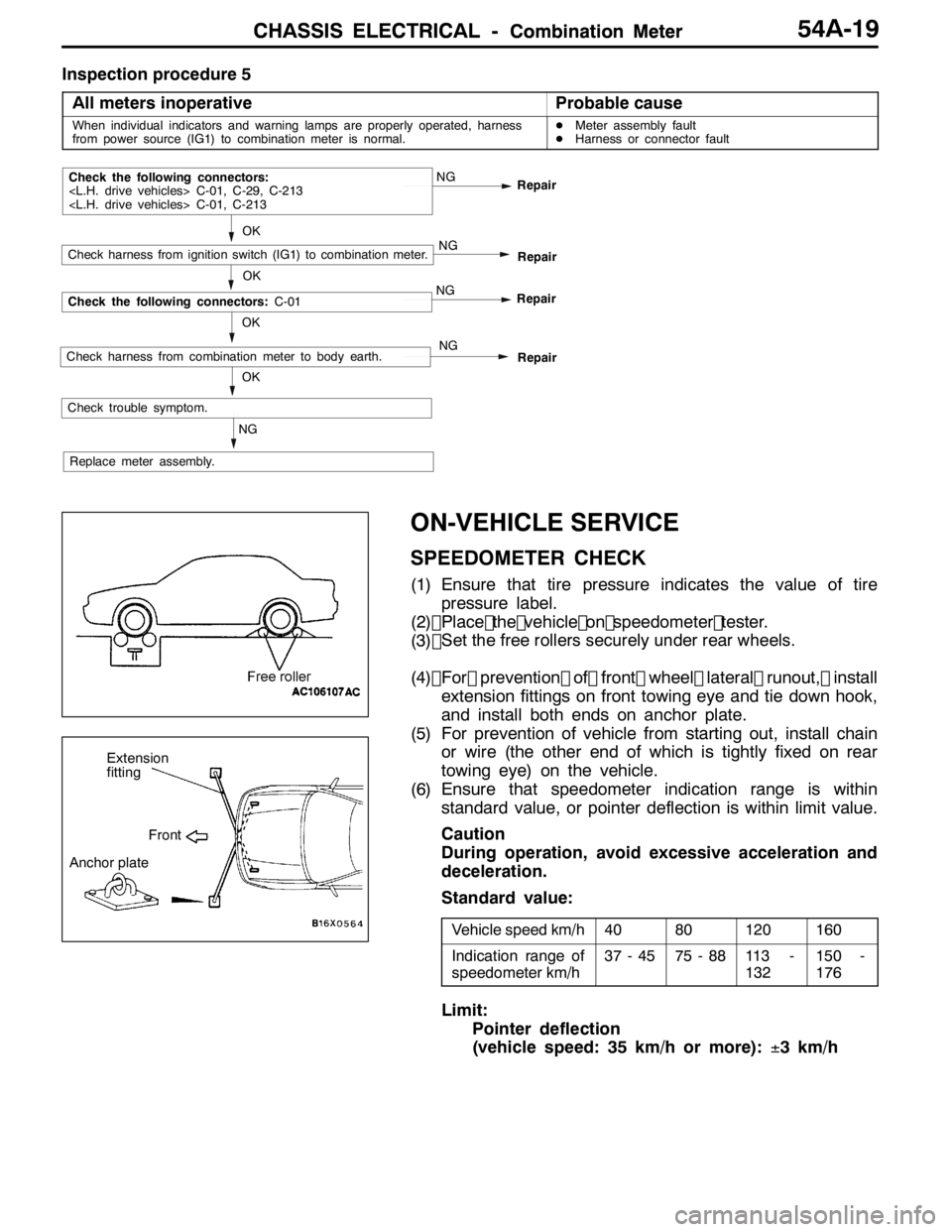
Inspection procedure 5All meters inoperative
Probable cause
When individual indicators and warning lamps are properly operated, harness
from power source (IG1) to combination meter is normal.D Meter assembly fault
D Harness or connector fault
NG Repair
NG
OK
Check trouble symptom. Repair
OK
Check the following connectors:
C-01, C-29, C-213
C-01, C-213
NG
Check harness from ignition switch (IG1) to combination meter.
Replace meter assembly. Repair
NG
OK
Check the following connectors:
C-01
NG
RepairCheck harness from combination meter to body earth.
ON-VEHICLE SERVICE
SPEEDOMETER CHECK
(1) Ensure that tire pressure indicates the value of tirepressure label.
(2) Place the vehicle on speedometer teste r.
(3)
(4) For prevention of front wheel lateral runout, install
extension fittings on front towing eye and tie down hook,
and install both ends on anchor plate.
(5) For prevention of vehicle from starting out, install chain or wire (the other end of which is tightly fixed on rear
towing eye) on the vehicle.
(6) Ensure that speedometer indication range is within standard value, or pointer deflection is within limit value.
Caution
During operation, avoid excessive acceleration and
deceleration.
Standard value:
Vehicle speed km/h4080120160
Indication range of
speedometer km/h37 - 4575 - 8811 3 -
132150 -
176
Limit:
Pointer deflection
(vehicle speed: 35 km/h or more): ±3 km/h
Extension
fitting
Front
Anchor plate
OK
Set the free rollers securely under rear wheels.
Page 1368 of 1449
SWS -Troubleshooting54B-4
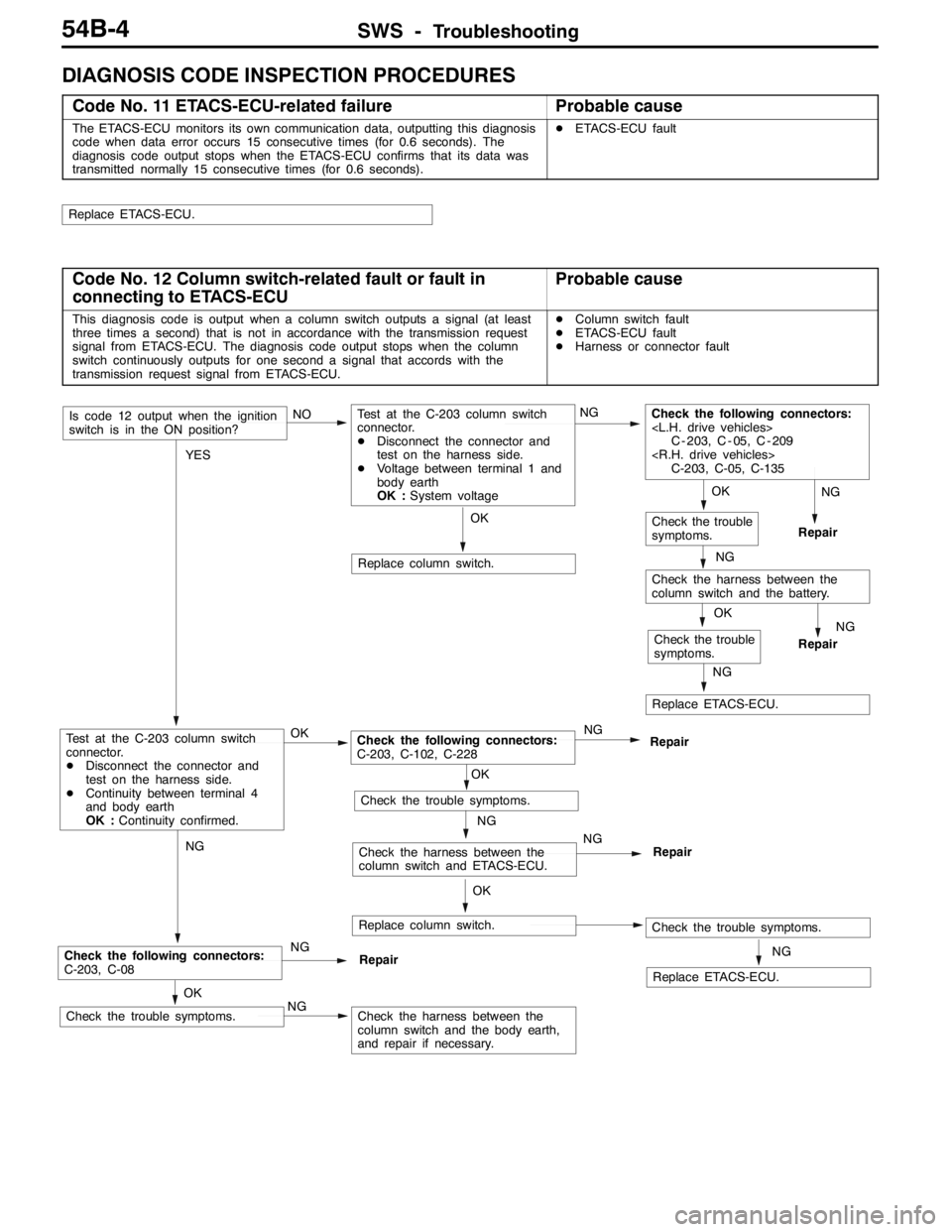
DIAGNOSIS CODE INSPECTION PROCEDURES
Code No. 11 ETACS-ECU-related failureProbable cause
The ETACS-ECU monitors its own communication data, outputting this diagnosis
code when data error occurs 15 consecutive times (for 0.6 seconds). The
diagnosis code output stops when the ETACS-ECU confirms that its data was
transmitted normally 15 consecutive times (for 0.6 seconds).DETACS-ECU fault
Replace ETACS-ECU.
Code No. 12 Column switch-related fault or fault in
connecting to ETACS-ECUProbable cause
This diagnosis code is output when a column switch outputs a signal (at least
three times a second) that is not in accordance with the transmission request
signal from ETACS-ECU. The diagnosis code output stops when the column
switch continuously outputs for one second a signal that accords with the
transmission request signal from ETACS-ECU.DColumn switch fault
DETACS-ECU fault
DHarness or connector fault
OK
Replace column switch.
NG
Replace ETACS-ECU.
OK
Check the trouble
symptoms.
OK
Check the trouble symptoms.NGCheck the harness between the
column switch and the body earth,
and repair if necessary.
NG
Check the following connectors:
C-203, C-08NG
Repair
NG
Repair
NG
Check the harness between the
column switch and the battery.
OK
Check the trouble
symptoms.
NG
Replace ETACS-ECU.
OK
Replace column switch.Check the trouble symptoms.
NG
Check the harness between the
column switch and ETACS-ECU.NG
Repair
OK
Check the trouble symptoms.
YES
Test at the C-203 column switch
connector.
DDisconnect the connector and
test on the harness side.
DContinuity between terminal 4
and body earth
OK :Continuity confirmed.OKCheck the following connectors:
C-203, C-102, C-228NG
Repair
Is code 12 output when the ignition
switch is in the ON position?NOTest at the C-203 column switch
connector.
DDisconnect the connector and
test on the harness side.
DVoltage between terminal 1 and
body earth
OK :System voltageNGCheck the following connectors:
C - 203, C - 05, C - 209
C-203, C-05, C-135
NG
Repair