Page 1075 of 1449
ABS <4WD> -Troubleshooting35B-5
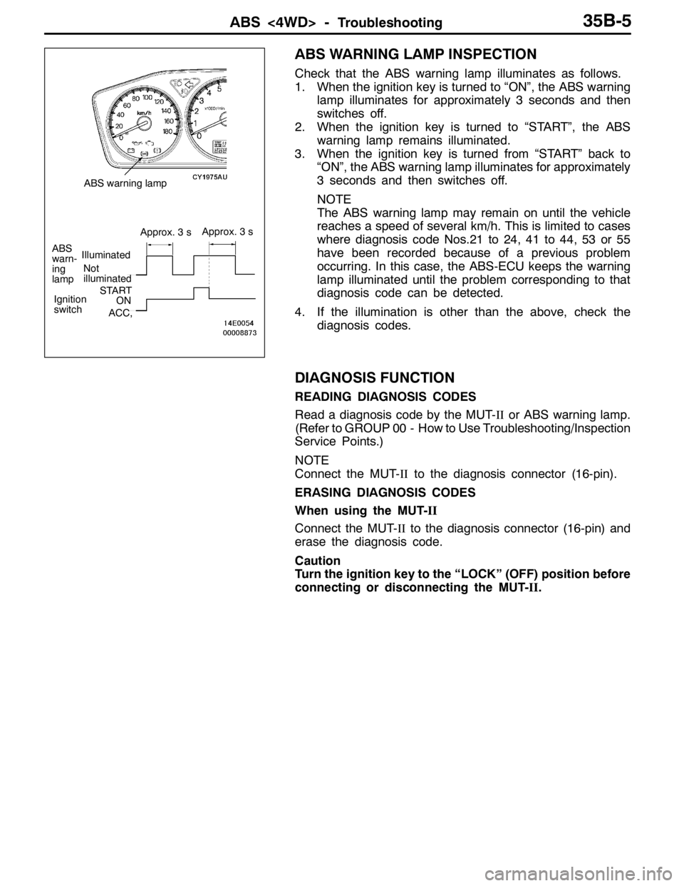
ABS WARNING LAMP INSPECTION
Check that the ABS warning lamp illuminates as follows.
1. When the ignition key is turned to “ON”, the ABS warning
lamp illuminates for approximately 3 seconds and then
switches off.
2. When the ignition key is turned to “START”, the ABS
warning lamp remains illuminated.
3. When the ignition key is turned from “START” back to
“ON”, the ABS warning lamp illuminates for approximately
3 seconds and then switches off.
NOTE
The ABS warning lamp may remain on until the vehicle
reaches a speed of several km/h. This is limited to cases
where diagnosis code Nos.21 to 24, 41 to 44, 53 or 55
have been recorded because of a previous problem
occurring. In this case, the ABS-ECU keeps the warning
lamp illuminated until the problem corresponding to that
diagnosis code can be detected.
4. If the illumination is other than the above, check the
diagnosis codes.
DIAGNOSIS FUNCTION
READING DIAGNOSIS CODES
Read a diagnosis code by the MUT-IIor ABS warning lamp.
(Refer to GROUP 00 - How to Use Troubleshooting/Inspection
Service Points.)
NOTE
Connect the MUT-IIto the diagnosis connector (16-pin).
ERASING DIAGNOSIS CODES
When using the MUT-II
Connect the MUT-IIto the diagnosis connector (16-pin) and
erase the diagnosis code.
Caution
Turn the ignition key to the “LOCK” (OFF) position before
connecting or disconnecting the MUT-II.
Not
illuminated
ABS
warn-
ing
lampIlluminated
Approx. 3 sApprox. 3 s
Ignition
switchSTARTON
ACC,
ABS warning lamp
Page 1076 of 1449
ABS <4WD> -Troubleshooting35B-6
When not using the MUT-II
NOTE
If the ABS-ECU function has been stopped because of fail-safe
operation, it will not be possible to erase the diagnosis codes.
1. Stop the engine.
2. Use the special tool to earth terminal (1) (diagnosis control
terminal) of the diagnosis connector.
3. Turn on the stop lamp switch. (Depress the brake pedal.)
4. After carrying out steps 1. to 3., turn the ignition switch
to “ON”. Within 3 seconds after turning the ignition switch
to “ON”, turn off the stop lamp switch (release the brake
pedal). Then, turn the stop lamp switch on and off a
total of 10 times.
1st2nd3rd4th5th6th7th8th9th10th
Within
1
secondWithin
1
secondWithin
1
secondWithin
1
secondWithin
1
secondWithin
1
secondWithin
1
secondWithin
1
secondWithin
1
secondWithin
1
second
1 second
Ignition switchON
LOCK (OFF)
Stop lamp switchON
OFF
ABS warning lampON
OFF
ABS-ECU memory
Within 3
seconds
Erasing of ABS-ECU
diagnosis codes complete.
MB991529
Page 1078 of 1449
ABS <4WD> -Troubleshooting35B-8
Diagnosis code No.Reference page Inspection item
81Steering wheel sensor (ST-1) system (Open circuit or short circuit)35B-14
82Steering wheel sensor (ST-2) system (Open circuit or short circuit)
83Steering wheel sensor (ST-N) system (Open circuit or short circuit)
NOTE: diagnosis code No.16, 52, 63
1. Code No. 16 is cleared from the memory by turning the ignition switch to ACC position. When the system
is properly reset, this code is also cleared from the memory.
2. Code No. 52 and 63 are cleared from the memory by turning the ignition switch to ACC position.
Page 1080 of 1449
ABS <4WD> -Troubleshooting35B-10
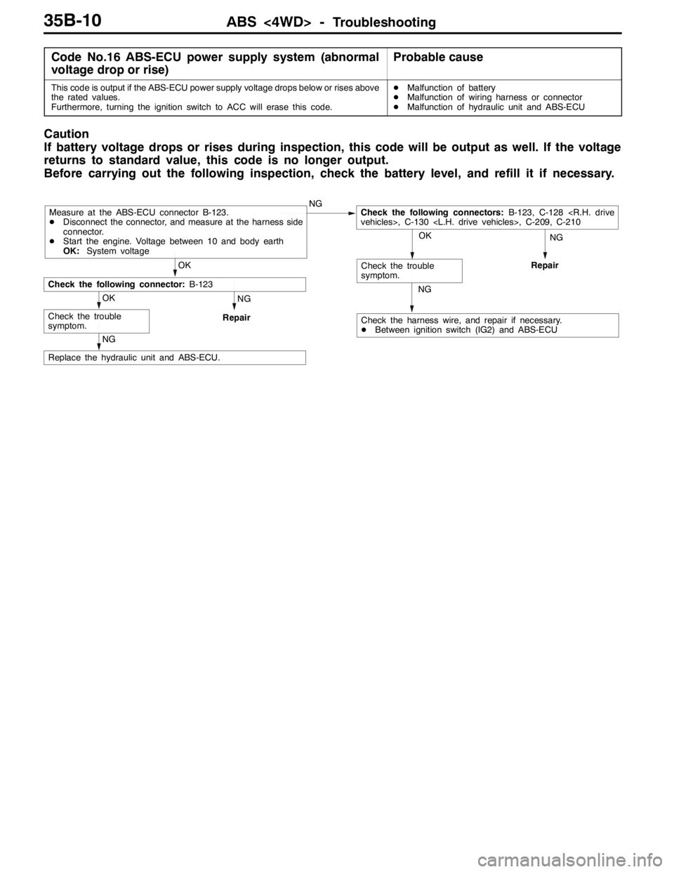
Code No.16 ABS-ECU power supply system (abnormal
voltage drop or rise)Probable cause
This code is output if the ABS-ECU power supply voltage drops below or rises above
the rated values.
Furthermore, turning the ignition switch to ACC will erase this code.DMalfunction of battery
DMalfunction of wiring harness or connector
DMalfunction of hydraulic unit and ABS-ECU
Caution
If battery voltage drops or rises during inspection, this code will be output as well. If the voltage
returns to standard value, this code is no longer output.
Before carrying out the following inspection, check the battery level, and refill it if necessary.
NGNG
Repair
NG
Replace the hydraulic unit and ABS-ECU.
NG
Repair
Check the harness wire, and repair if necessary.
DBetween ignition switch (IG2) and ABS-ECU
OK
Check the trouble
symptom.
OK
Check the trouble
symptom.
OK
Check the following connector:B-123
NGCheck the following connectors:B-123, C-128
vehicles>, C-130 , C-209, C-210Measure at the ABS-ECU connector B-123.
DDisconnect the connector, and measure at the harness side
connector.
DStart the engine. Voltage between 10 and body earth
OK:System voltage
Page 1081 of 1449
ABS <4WD> -Troubleshooting35B-11
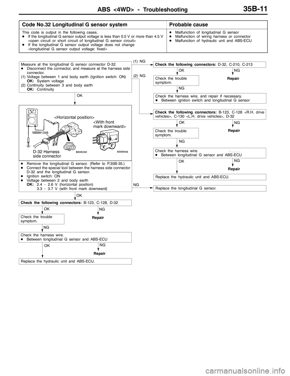
Code No.32 Longitudinal G sensor systemProbable cause
This code is output in the following cases.
DIf the longitudinal G sensor output voltage is less than 0.5 V or more than 4.5 V
DIf the longitudinal G sensor output voltage does not change
DMalfunction of longitudinal G sensor
DMalfunction of wiring harness or connector
DMalfunction of hydraulic unit and ABS-ECU
(1) NG
NG
Repair
NG
Check the harness wire, and repair if necessary.
DBetween ignition switch and longitudinal G sensor
OK
Check the trouble
symptom.
Check the following connectors:D-32, C-210, C-213
NG
Repair
NG
OK
Check the trouble
symptom. OK
(2) NG
Measure at the longitudinal G sensor connector D-32.
DDisconnect the connector, and measure at the harness side
connector.
(1) Voltage between 1 and body earth (Ignition switch: ON)
OK:System voltage
(2) Continuity between 3 and body earth
OK:Continuity
Repair
Check the following connectors:B-123, C-128
vehicles>, C-130 , D-32
NGOK
Repair
Check the harness wire.
DBetween longitudinal G sensor and ABS-ECU
Replace the hydraulic unit and ABS-ECU.
MB991348
mark downward>
D-32 Harness
side connector
NG
OK
NG
Repair
NG
OK
Check the trouble
symptom.
Check the following connectors:B-123, C-128, D-32
DRemove the longitudinal G sensor. (Refer to P.35B-35.)
DConnect the special tool between the harness side connector
D-32 and the longitudinal G sensor.
DIgnition switch: ON
DVoltage between 2 and body earth
OK:2.4 - 2.6 V (horizontal position)
3.3 - 3.7 V (with front mark downward)
NGOK
Repair
Check the harness wire.
DBetween longitudinal G sensor and ABS-ECU
Replace the hydraulic unit and ABS-ECU.
Replace the longitudinal G sensor.
Page 1083 of 1449
ABS <4WD> -Troubleshooting35B-13
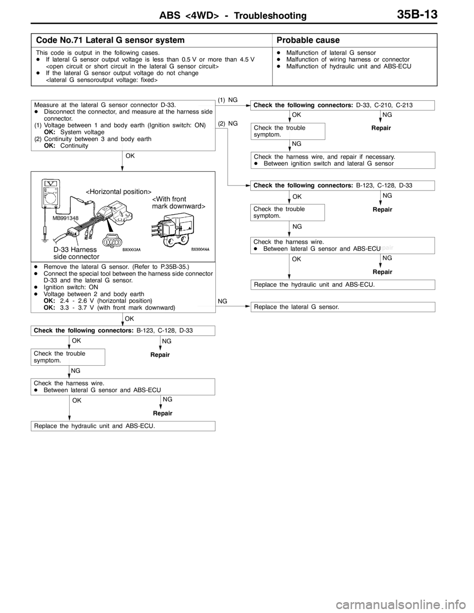
Code No.71 Lateral G sensor systemProbable cause
This code is output in the following cases.
DIf lateral G sensor output voltage is less than 0.5 V or more than 4.5 V
DIf the lateral G sensor output voltage do not change
DMalfunction of lateral G sensor
DMalfunction of wiring harness or connector
DMalfunction of hydraulic unit and ABS-ECU
(1) NG
NG
Repair
NG
Check the harness wire, and repair if necessary.
DBetween ignition switch and lateral G sensor
OK
Check the trouble
symptom.
Check the following connectors:D-33, C-210, C-213
NG
Repair
NG
OK
Check the trouble
symptom. OK
(2) NG
Measure at the lateral G sensor connector D-33.
DDisconnect the connector, and measure at the harness side
connector.
(1) Voltage between 1 and body earth (Ignition switch: ON)
OK:System voltage
(2) Continuity between 3 and body earth
OK:Continuity
Repair
Check the following connectors:B-123, C-128, D-33
NGOK
Repair
Check the harness wire.
DBetween lateral G sensor and ABS-ECU
Replace the hydraulic unit and ABS-ECU.
MB991348
mark downward>
D-33 Harness
side connector
NG
OK
NG
Repair
NG
OK
Check the trouble
symptom.
Check the following connectors:B-123, C-128, D-33
DRemove the lateral G sensor. (Refer to P.35B-35.)
DConnect the special tool between the harness side connector
D-33 and the lateral G sensor.
DIgnition switch: ON
DVoltage between 2 and body earth
OK:2.4 - 2.6 V (horizontal position)
OK:3.3 - 3.7 V (with front mark downward)
NGOK
Repair
Check the harness wire.
DBetween lateral G sensor and ABS-ECU
Replace the hydraulic unit and ABS-ECU.
Replace the lateral G sensor.
Page 1084 of 1449
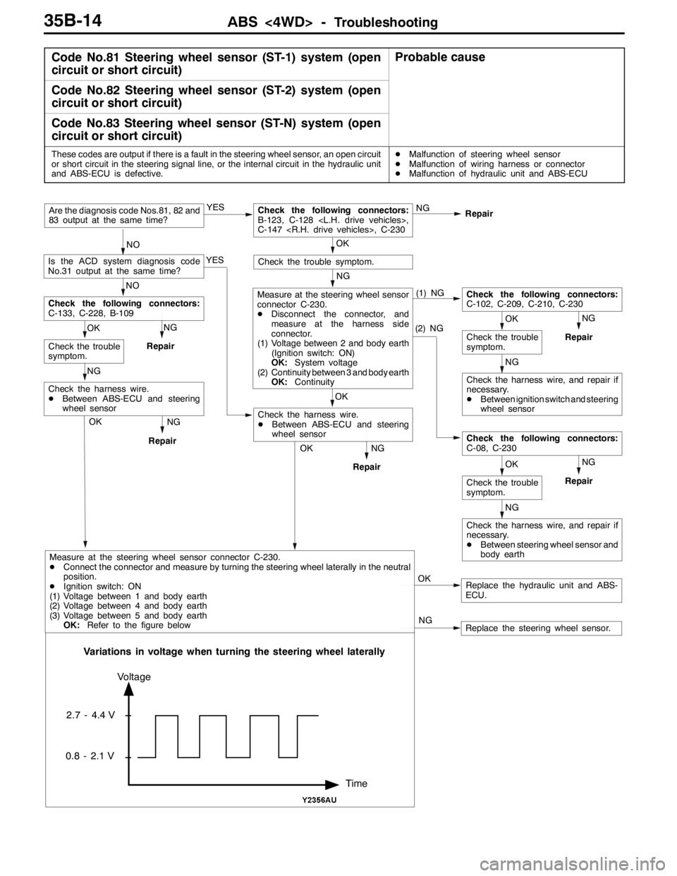
ABS <4WD> -Troubleshooting35B-14
Code No.81 Steering wheel sensor (ST-1) system (open
circuit or short circuit)Probable cause
Code No.82 Steering wheel sensor (ST-2) system (open
circuit or short circuit)
Code No.83 Steering wheel sensor (ST-N) system (open
circuit or short circuit)
These codes are output if there is a fault in the steering wheel sensor, an open circuit
or short circuit in the steering signal line, or the internal circuit in the hydraulic unit
and ABS-ECU is defective.DMalfunction of steering wheel sensor
DMalfunction of wiring harness or connector
DMalfunction of hydraulic unit and ABS-ECU
NG
Repair
Replace the hydraulic unit and ABS-
ECU. OK NG YES
Repair
NOAre the diagnosis code Nos.81, 82 and
83 output at the same time?
OKCheck the following connectors:
B-123, C-128 ,
C-147 , C-230
YES
NO
Is the ACD system diagnosis code
No.31 output at the same time?
NG
Check the trouble symptom.
(1) NG
(2) NGNG
Repair
NG
OK
Check the trouble
symptom.
Check the following connectors:
C-102, C-209, C-210, C-230
Check the harness wire, and repair if
necessary.
DBetween ignition switch and steering
wheel sensor
NG
OK
Check the trouble
symptom.
Check the following connectors:
C-08, C-230
Check the harness wire, and repair if
necessary.
DBetween steering wheel sensor and
body earth
OK
Measure at the steering wheel sensor
connector C-230.
DDisconnect the connector, and
measure at the harness side
connector.
(1) Voltage between 2 and body earth
(Ignition switch: ON)
OK:System voltage
(2) Continuity between 3 and body earth
OK:Continuity
NG
RepairOK
Check the harness wire.
DBetween ABS-ECU and steering
wheel sensor NG
Repair
NG OK
Check the trouble
symptom.
Check the following connectors:
C-133, C-228, B-109
NG
Repair
Check the harness wire.
DBetween ABS-ECU and steering
wheel sensor
OK
Replace the steering wheel sensor. NG
Time Voltage
2.7 - 4.4 V
0.8 - 2.1 V
Variations in voltage when turning the steering wheel laterally
Measure at the steering wheel sensor connector C-230.
DConnect the connector and measure by turning the steering wheel laterally in the neutral
position.
DIgnition switch: ON
(1) Voltage between 1 and body earth
(2) Voltage between 4 and body earth
(3) Voltage between 5 and body earth
OK:Refer to the figure below
Page 1085 of 1449

ABS <4WD> -Troubleshooting35B-15
INSPECTION CHART FOR TROUBLE SYMPTOMS
Trouble symptomsInspection procedure
No.Reference page
Communication between the MUT-IIand the whole system is not
possible.135B-16
Communication between the MUT-IIand the ABS-ECU is not possible.235B-17
When the ignition key is turned to “ON” (engine stopped), the ABS
warning lamp does not illuminate.335B-18
Even after the engine is started, the ABS warning lamp remains
illuminated.435B-18
In the inspection with MUT-II service data, the parking brake switch is not
turned ON or turn OFF.535B-19
The neutral position learning of the steering wheel sensor is not finished.635B-20
Faulty ABS operation735B-21
Caution
1. If steering movements are made when driving at high speed, or when driving on road surfaces
with low frictional resistance, or when passing over bumps, the ABS may operate even though
sudden braking is not being applied. Because of this, when getting information from the customer,
check if the problem occurred while driving under such conditions as these.
2. During ABS operation, the brake pedal may vibrate or may not be able to be depressed. Such
phenomena are due to intermittent changes in hydraulic pressure inside the brake line to prevent
the wheels from locking and is not an abnormality.