2007 MITSUBISHI LANCER EVOLUTION ignition
[x] Cancel search: ignitionPage 1087 of 1449

ABS <4WD> -Troubleshooting35B-17
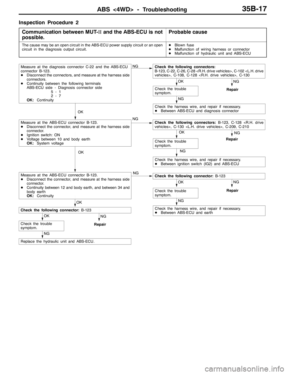
Inspection Procedure 2
Communication between MUT-IIand the ABS-ECU is not
possible.
Probable cause
The cause may be an open circuit in the ABS-ECU power supply circuit or an open
circuit in the diagnosis output circuit.DBlown fuse
DMalfunction of wiring harness or connector
DMalfunction of hydraulic unit and ABS-ECU
NG OK
NG
NG NG
Repair
Check the harness wire, and repair if necessary.
DBetween ABS-ECU and diagnosis connector
OK
NG
Repair
NG
Check the harness wire, and repair if necessary.
DBetween ignition switch (IG2) and ABS-ECU
OK
NG
Repair
NG
Check the harness wire, and repair if necessary.
DBetween ABS-ECU and earth
NG
Repair
NG
Replace the hydraulic unit and ABS-ECU.
OK
Check the trouble
symptom.
OK
Check the trouble
symptom.
OK
Check the following connector:B-123
Measure at the ABS-ECU connector B-123.
DDisconnect the connector, and measure at the harness side
connector.
DContinuity between 12 and body earth, and between 34 and
body earth
OK:ContinuityCheck the following connector:B-123
OK
Check the trouble
symptom.
Measure at the ABS-ECU connector B-123.
DDisconnect the connector, and measure at the harness side
connector.
DIgnition switch: ON
DVoltage between 10 and body earth
OK:System voltageCheck the following connectors:B-123, C-128
Check the trouble
symptom.
Measure at the diagnosis connector C-22 and the ABS-ECU
connector B-123.
DDisconnect the connectors, and measure at the harness side
connectors.
DContinuity between the following terminals
ABS-ECU side - Diagnosis connector side
5-1
2-7
OK:ContinuityNGCheck the following connectors:
B-123, C-22, C-26, C-28
Page 1088 of 1449

ABS <4WD> -Troubleshooting35B-18
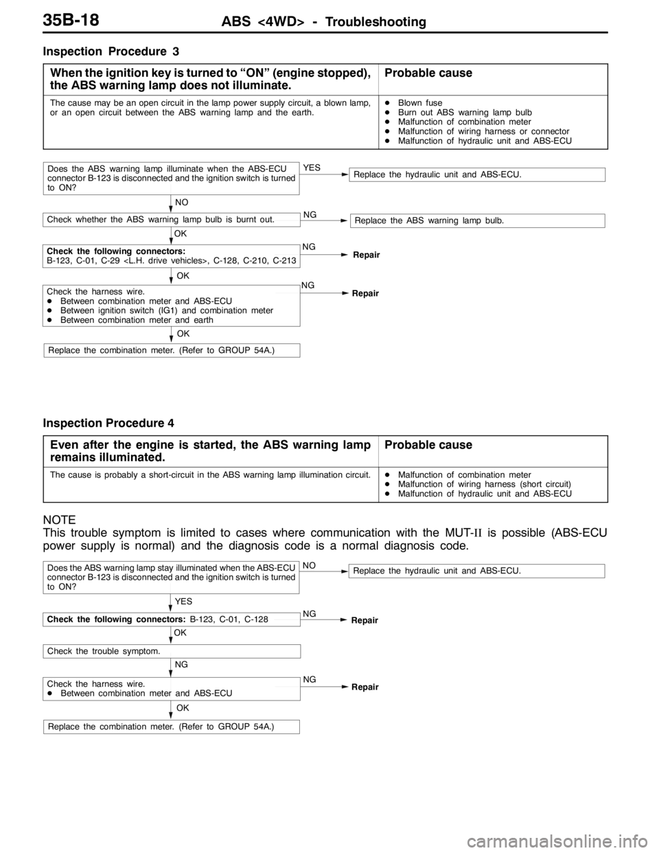
Inspection Procedure 3
When the ignition key is turned to “ON” (engine stopped),
the ABS warning lamp does not illuminate.
Probable cause
The cause may be an open circuit in the lamp power supply circuit, a blown lamp,
or an open circuit between the ABS warning lamp and the earth.DBlown fuse
DBurn out ABS warning lamp bulb
DMalfunction of combination meter
DMalfunction of wiring harness or connector
DMalfunction of hydraulic unit and ABS-ECU
NO
NG
Replace the ABS warning lamp bulb.
Check the harness wire.
DBetween combination meter and ABS-ECU
DBetween ignition switch (IG1) and combination meter
DBetween combination meter and earth
Replace the hydraulic unit and ABS-ECU.
OKNG
OK
Check the following connectors:
B-123, C-01, C-29
OK
Check whether the ABS warning lamp bulb is burnt out.
Does the ABS warning lamp illuminate when the ABS-ECU
connector B-123 is disconnected and the ignition switch is turned
to ON?YES
Repair
Replace the combination meter. (Refer to GROUP 54A.)NG
Repair
Inspection Procedure 4
Even after the engine is started, the ABS warning lamp
remains illuminated.
Probable cause
The cause is probably a short-circuit in the ABS warning lamp illumination circuit.DMalfunction of combination meter
DMalfunction of wiring harness (short circuit)
DMalfunction of hydraulic unit and ABS-ECU
NOTE
This trouble symptom is limited to cases where communication with the MUT-IIis possible (ABS-ECU
power supply is normal) and the diagnosis code is a normal diagnosis code.
YES
NG
Check the harness wire.
DBetween combination meter and ABS-ECU
Replace the hydraulic unit and ABS-ECU.
OK
NG
OK
Check the trouble symptom.
Does the ABS warning lamp stay illuminated when the ABS-ECU
connector B-123 is disconnected and the ignition switch is turned
to ON?NO
Repair
Replace the combination meter. (Refer to GROUP 54A.)NG
Repair
Check the following connectors:B-123, C-01, C-128
Page 1092 of 1449

ABS <4WD> -Troubleshooting35B-22
DATA LIST REFERENCE TABLE
The following items can be read by the MUT-IIfrom the ABS-ECU input data.
1. When the system is normal
Item No.Check itemChecking requirementsNormal value
11Front-right wheel speed sensorPerform a test runVehicle speeds
displayedonthe
12Front-left wheel speed sensor
displayedonthe
speedometer and
MUTIIareidentical13Rear-right wheel speed sensorMUT-IIareidentical.
14Rear-left wheel speed sensor
21Power supply voltageIgnition switch: ON10 - 16 V
29Parking brake switchPull the parking brake lever.ON
Release the parking brake lever.OFF
36Stop lamp switchDepress the brake pedal.ON
Release the brake pedal.OFF
37Steering wheel sensor neutral
position learningAfter driving straightly with vehicle speed more
than 10km/hON
Before driving with ignition switch ONOFF
71Lateral G sensorWhen vehicle stops2.4 - 2.6 V
When vehicle drives1.0 - 4.0 V
74Steering wheel sensor (ST-N)Ignition switch: ONSteering:
Neutral position and
position near by±
360_ON
Steering:
Except for aboveOFF
75Steering wheel sensor (ST-1)Ignition switch: ONSteering:
Turnlaterallyslowly
Display ON and OFF
alternately
76Steering wheel sensor (ST-2)
Turnlaterallyslowlyalternately
86Steering degreeIgnition switch: ON
Steering wheel sensor
tlitili
Steering: Steer by
90_to the right+90_
g
neutral position learning
is finished (service data
N37di lON)
Steering: NeutralOFF(
No. 37 displays ON)Steering: Steer by
90_to the left-90_
2. When the ABS-ECU shut off ABS operation
When the diagnosis system stops the ABS-ECU, the MUT-IIdisplay data will be unreliable.
Page 1094 of 1449

ABS <4WD> -Troubleshooting35B-24
CHECK AT ABS-ECU
Use the following steps to remove the connector cover and
measure the terminal voltage.
1. Move the lock lever of the ABS-ECU connector as shown
in the illustration, and then disconnect the ABS-ECU
connector.
2. Push up and unlock the hooks of the ABS-ECU connector
shown in the illustration, then remove the connector cover.
TERMINAL VOLTAGE CHECK CHART
1. Measure the voltage between each terminal and earth
(terminal No.12).
2. The terminal layout is shown in the illustration.
Terminal No.Check itemChecking requirementsNormal condition
1Parking brake switch
input
Parking brake switch: ON1 V or less
input
Parking brake switch: OFFSystem voltage
2MUT-IIWhen the MUT-IIis connectedSerial communication with MUT-II
When the MUT-IIis not connected1 V or less
3ABS ON output to
4WD ECU
With ABS active (reference)(0.5 V or less)
4WD-ECU
With ABS not activeSystem voltage
4Steering wheel sensor
(ST-N) inputIgnition
switch: ONSteering wheel: Neutral
position and position
near by±360_0.8 - 2.1 V
Steering wheel: Except
for above2.7 - 4.4 V
5Diagnosis changeover
input
When the MUT-IIis connected0V
input
When the MUT-IIis not connectedApprox. 12 V
Lock lever
Page 1095 of 1449

ABS <4WD> -Troubleshooting35B-25
Terminal No. Normal conditionChecking requirements Check item
10ABS-ECU power
supply
Ignition switch: ONSystem voltage
supply
Ignition switch: START or ACC0V
11Solenoid valve power
supplyAlwaysSystem voltage
14Lateral G sensor inputIgnition switch: ON2.4 - 2.6 V (horizontal position)
15Longitudinal G sensor
earthAlways0V
17Steering wheel sensor
(ST-2) inputIgnition
switch: ONSteering wheel: Turn
laterallyVariation in the voltage value 0.8 -
2.1 V and 2.7 - 4.4 V
18Wheel speed sensor
(front right) outputMoving forward slowly0-5V
19Stop lamp monitor
input
Ignition
switch:ON
Stop lamp switch: ONSystem voltage
inputswitch:ON
Stop lamp switch: OFF1 V or less
20Wheel speed sensor
(rear left) outputMoving forward slowly0-5V
21Wheel speed sensor
(rear right) outputMoving forward slowly0-5V
24Lateral G sensor earthAlways0V
25Longitudinal G sensor
inputIgnition switch: ON2.4 - 2.6 V (horizontal position)
26Steering wheel sensor
(ST-1) inputIgnition
switch: ONSteering wheel: Turn
laterallyVariation in the voltage value 0.8 -
2.1 V and 2.7 - 4.4 V
27ABS warning lamp
transistor outputIgnition
switch: ONWhen the lamp is
switched off1 V or less
When the lamp is
illuminated7 V or more
32Wheel speed sensor
(front left) outputMoving forward slowly0-5V
33Motor power supplyAlwaysSystem voltage
Page 1096 of 1449

ABS <4WD> -Troubleshooting/On-vehicle Service35B-26
RESISTANCE AND CONTINUITY BETWEEN
HARNESS-SIDE CONNECTOR TERMINALS
1. Turn the ignition key to the “LOCK” (OFF) position.
2. Disconnect the ABS-ECU connector.
3. Check the resistance and continuity between the terminals
indicated in the table below.
4. The terminal layout is shown in the illustration.
ABS-ECU terminal No.SignalNormal condition
6-7Wheel speed sensor (rear left)1.24 - 1.64 kΩ
8-9Wheel speed sensor (rear right)
22 - 31Wheel speed sensor (front left)
29 - 30Wheel speed sensor (front right)
12 - Body earthEarthContinuity
34 - Body earthEarth
ON-VEHICLE SERVICE
WHEEL SPEED SENSOR OUTPUT VOLTAGE
CHECK
1. Lift up the vehicle and release the parking brake.
2. Move the lock lever of the ABS-ECU connector as shown
in the illustration, and then disconnect the ABS-ECU
connector.
3. Push up and unlock the hooks of the ABS-ECU connector
shown in the illustration, then remove the connector cover.
Lock lever
Page 1098 of 1449

ABS <4WD> -On-vehicle Service35B-28
SymptomRemedy Probable causes
Noisy or disturbed waveformOpen circuit in sensorReplace sensor
Open circuit in harnessCorrect harness
Incorrectly mounted wheel speed sensorMount correctly
ABS rotor with missing or damaged teethReplace ABS rotor
Caution
Because the wheel speed sensor cables move together with the front and rear suspension, they
vibrate greatly when driving over poor road surfaces. As a result, the sensor harnesses should also
be shaken when monitoring of output waveforms of the wheel speed sensors in order to simulate
conditions such as driving over poor road surfaces.
HYDRAULIC UNIT CHECK
1. Jack up the vehicle and support the vehicle with rigid racks placed at the specified jack-up points
or place the wheels which are checked on the rollers of the braking force tester.
Caution
(1) The roller of the braking force tester and the tyre should be dry during testing.
(2) When testing the front brakes, apply the parking brake, and when testing the rear brakes,
stop the front wheels by chocking them.
2. Turn the ignition key to the “LOCK” (OFF) position and set the MUT-II.
Caution
Turn the ignition key to the “LOCK” (OFF) position before connecting or disconnecting the
MUT-II.
3. After checking that the shift lever is in neutral, start the engine.
4. Use the MUT-IIto force-drive the actuator.
NOTE
(1) During the actuator test, the ABS warning lamp will illuminate and the anti-skid control will be
cancelled.
(2) When the ABS has been interrupted by the fail-safe function, the MUT-IIactuator testing cannot
be carried out.
5. Turn the wheel by hand and check the change in braking force when the brake pedal is depressed.
When using the braking force tester, depress the brake pedal until the braking force is at the following
values, and check that the braking force decreases when the actuator is force-driven.
Front wheel785 - 981 N
Rear wheel588 - 784 N
Page 1099 of 1449

ABS <4WD> -On-vehicle Service35B-29
The result should be as shown in the following diagram.
Approx. 0.05 seconds
Pedal operationDepressed
Released
Solenoid valve
positionIncrease in pressure
Steady pressure
Reduction in pressure
Checking the
brake forceLock
Drag force when the pedal is freeMUT-IIactuator test
(Item No. 01, 02, 03, 04) start
2 seconds
1 seconds
6. If the result of inspection is abnormal, correct according to the following “Diagnosis Table.”
Diagnosis Table
No.MUT-II
display
OperationJudgementProbable
cause
Remedy
display
NormalAbnormal
cause
01FR VALVE(1) Depress the brake
pedal to lock wheel.
(2) Using the MUT-II,
select the wheel to be
checkedandforcethe
Brake force
released for 3
seconds after
locking.Wheel does
not lock when
brake pedal
is depressed.Clogged
brake line
other than
hydraulic unitCheck and
clean brake
line.
02FL VALVEchecked and force the
actuator to operate.
(3) Check the brake force
for the selected wheel
using a brake force
ttbttith
Clogged
hydraulic
circuit in
hydraulic unitReplace
hydraulic unit
assembly.
03RR VALVE
g
tester or by rotating the
wheel by hand.Brake force is
not released.Incorrect
hydraulic unit
brake tube
connectionConnect
correctly.
04RL VALVEHydraulic unit
solenoid
valve not
functioning
correctlyReplace
hydraulic unit
assembly.
7. After checking, turn the ignition switch to the “LOCK” (OFF) position and then disconnect the MUT-II.
REMEDY FOR A FLAT BATTERY
When booster cables are used to start the engine when the
battery is completely flat and then the vehicle is immediately
driven without waiting for the battery to recharge itself to
some extent, the engine may misfire, and driving might not
be possible. This happens because ABS consumes a great
amount of current for its self-check function. If this happens,
recharge the battery fully.
Caution
The vehicle posture will be unstable during braking, so
do not drive the vehicle with the ABS-ECU connector
disconnected or with the ABS not operating for any other
reason.