2007 MITSUBISHI LANCER EVOLUTION ignition
[x] Cancel search: ignitionPage 1302 of 1449

SRS - Air Bag Modules and Clock Spring52B-58
"CASTEERING WHEEL/STEERING WHEEL - AIR BAG
MODULE ASSEMBLY INSTALLATION
1. After checking that centering of the clock spring has been
done, install the steering wheel or the steering wheel - air
bag module assembly.
Caution
Do not engage the harness of the clock spring when
installing the steering wheel or the steering wheel - air
bag module assembly.
2. After installation, check that no abnormalities occur when
the steering wheel is fully turned to the left or the right.
"DAPOST-INSTALLATION INSPECTION
1. Check that no abnormal noise or improper operation can
be caused by rotating the steering wheel in left and right
directions slightly.
(driver’s air bag module, clock spring)
2. Turn the ignition switch to the ON position.
3. Check that the SRS warning lamp illuminates for 6 to
8 seconds and goes out.
4. Carry out troubleshooting if the lamp does not go out.
(Refer to P.52-6.)
SRS warning lamp
Page 1305 of 1449

SRS -Seat Belt with Pre-tensioner52B-61
SEAT BELT WITH PRE-TENSIONER
Caution:
1. Wait for at least 60 seconds after
disconnecting the negative ( - ) terminal of
the battery before starting any operation.The
removed negative ( - ) terminal must be
protected by wrapping the tape. (Refer to
P.52B-3.)
2. Never disassemble or repair the seat belt
with pre-tensioner. Replace the part with a
new one when it malfunctions.
3. Take an extra care to deal with the seat belt
with pre-tensioner by avoiding dropping or
wetting it with water or oil. If any dent, crack,
or deformation is found, be sure to replace
the seat belt with pre-tensioner with a new
part.4. Do not place a heavy object on top of the
seat belt pre-tensioner.
5. Never keep the seat belt with pre-tensioner
in a place where the temperature can exceed
over 90_C.
6. Replace the seat belt with pre-tensioner with
a new one after operating the seat belt
pre-tensioner.
7. Wear gloves or protective glasses when
handling the seat belt with pre-tensioner
after operation.
8. If the seat belt with pre-tensioner before
operation needs to be discarded, be sure
to do so after operating the seat belt
pre-tensioner. (Refer to P.52B-64.)
REMOVAL AND INSTALLATION
Pre - removal operation
DTurn the ignition key to the LOCK(OFF) position.
DDisconnect the negative ( - ) terminal of the battery.
1 4
3
2
44±10 NSm
44±10 NSm
5
Removal steps
1. Sash cover guide
2. Seat belt lower anchor bolt
3. Bracket
4. Seat belt shoulder anchor bolt
DCenter pillar lower trim
(Refer to GROUP 52A - Trim.)
5. Seat belt pre-tensionerInstallation steps
"AA
DPre - installation inspection
5. Seat belt pre-tensioner
4. Seat belt shoulder anchor bolt
3. Bracket
2. Seat belt lower anchor bolt
DCenter pillar lower trim
(Refer to GROUP 52A - Trim.)
1. Sash cover guide
DNegative ( - ) terminal of the battery
connection
"BADPost - installation inspection
Page 1306 of 1449

SRS -Seat Belt with Pre-tensioner52B-62
INSTALLATION SERVICE POINTS
"AAPRE-INSTALLATION INSPECTION
1. Pre-installation inspection must be carried out even when
installing a new seat belt with pre-tensioner. (Refer to
Inspections.)
Caution
If the seat belt with pre-tensioner is discarded, discard
it after operating the seat belt pre-tensioner according
to the specified procedure. (Refer to P.52B-64.)
2. Connect the negative ( - ) terminal of the battery.
3. Connect the MUT-II to the diagnosis connector (16 pin).
Caution
Connection and disconnection of the MUT-II must be
carried out after turning the ignition switch to the
LOCK (OFF) position.
4. Turn the ignition switch to ON position.
5. Check that there is no abnormality except for open circuit
in the seat belt pre-tensioner after reading diagnostic
codes.
6. Turn the ignition key to LOCK (OFF) position.
7. Release the negative ( - ) terminal cable of the battery
and wrap a tape around it for insulation.
Caution
Wait for at least 60 seconds after disconnecting the
negative ( - ) battery cable before starting any
operation. (Refer to P.52B-3.)
"BAPOST-INSTALLATION INSPECTION
1. Turn the ignition switch to the ON position.
2. Check that the SRS warning lamp illuminates for 6 to
8 seconds and goes out.
3. Carry out troubleshooting if the lamp does not go out.
(Refer to P.52B-6.)
SRS warning lamp
Page 1322 of 1449

54A-2
CHASSIS
ELECTRICAL
CONTENTS
BATTERY 4..............................
SERVICE SPECIFICATION 4....................
ON-VEHICLE SERVICE 4......................
Fluid Level and Specific Gravity Check 4........
Charging 4.................................
Battery Testing Procedure 5...................
IGNITION SWITCH AND IMMOBILIZER
SYSTEM 6...............................
SPECIAL TOOLS 6............................
TROUBLESHOOTING 6........................
IMMOBILIZER-ECU CHECK 10.................
IGNITION SWITCH 11..........................
COMBINATION METER 14................
SERVICE SPECIFICATIONS 14.................
SEALANT 14..................................
SPECIAL TOOLS 15...........................
TROUBLESHOOTING 15.......................
ON-VEHICLE SERVICE 19.....................Speedometer Check 19......................
Tachometer Check 20........................
Fuel Gauge Unit Check 20....................
Engine Coolant Temperature Gauge
Unit Check 21...............................
COMBINATION METER 22.....................
HEADLAMP ASSEMBLY 24...............
SERVICE SPECIFICATIONS 24.................
TROUBLESHOOTING 24.......................
ON-VEHICLE SERVICE 24.....................
Headlamp Aiming 24.........................
Headlamp Intensity Measurement 28...........
Headlamp Bulb(low beam)Replacement28 ....
Headlamp Bulb(high beam)Replacement29 ...
Position Lamp Bulb Replacement29 ...........
Front Turn Signal Lamp Bulb Replacement29 ...
Headlamp Auto Cut Adjustment Procedure29 ...
HeadlampAuto Cut Function Check 29.........
HEADLAMP ASSEMBLY 30....................
CONTINUED ON NEXT PAGE
Page 1326 of 1449

CHASSIS ELECTRICAL -Ignition Switch and Immobilizer System54A-6
IGNITION SWITCH AND IMMOBILIZER SYSTEM
SPECIAL TOOLS
ToolNumberNameUse
MB991502MUT-IISub as-
semblyChecking the immobilizer system
MB990784Ornament removerInstrument panel under cover and column
cover removal
TROUBLESHOOTING
IGNITION SWITCH
The ignition switch is controlled by the Smart Wiring System (SWS). For troubleshooting procedures,
refer to GROUP 54B.
IMMOBILIZER
STANDARD FLOW OF DIAGNOSIS TROUBLESHOOTING
Refer to GROUP 00 - How to Use Troubleshooting/Inspection Service Points.
DIAGNOSIS FUNCTION
READING DIAGNOSIS CODES
The diagnosis codes can be read using the MUT-IIor by using the Simple Check Diagnosis mode. (Refer
to GROUP 00 - How to Use Troubleshooting/Inspection Service Points.)
NOTE
Connect the MUT-IIto the 16-pin diagnosis connector (black).
DIAGNOSIS CODE MEMORY ERASING PROCEDURE
Refer to GROUP 00 - How to Use Troubleshooting/Inspection Service Points.
INSPECTION USING SIMPLE CHECK DIAGNOSIS MODE
1. Change to Simple Check Diagnosis mode and activate switch diagnosis mode. (Refer to GROUP
00 - How to Use Troubleshooting/Inspection Service Points.)
2. In this condition, the input signals for the following switches can be checked.
CHART CLASSIFIED BY DIAGNOSIS CODES
Code No.Diagnosis contentsReference page
11Problem related to communication with the ignition key54A-7
12Ignition key is not registered, or encrypted code from ignition key does not match.54A-7
Page 1327 of 1449

CHASSIS ELECTRICAL -Ignition Switch and Immobilizer System54A-7
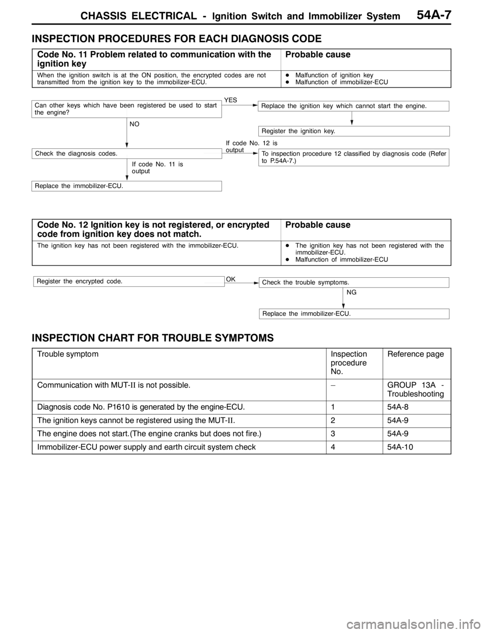
INSPECTION PROCEDURES FOR EACH DIAGNOSIS CODE
Code No. 11 Problem related to communication with the
ignition keyProbable cause
When the ignition switch is at the ON position, the encrypted codes are not
transmitted from the ignition key to the immobilizer-ECU.DMalfunction of ignition key
DMalfunction of immobilizer-ECU
YES
NOCan other keys which have been registered be used to start
the engine?Replace the ignition key which cannot start the engine.
If code No. 12 is
output
Check the diagnosis codes.To inspection procedure 12 classified by diagnosis code (Refer
to P.54A-7.)
Replace the immobilizer-ECU.
Register the ignition key.
If code No. 11 is
output
Code No. 12 Ignition key is not registered, or encrypted
code from ignition key does not match.Probable cause
The ignition key has not been registered with the immobilizer-ECU.DThe ignition key has not been registered with the
immobilizer-ECU.
DMalfunction of immobilizer-ECU
OK
NG
Replace the immobilizer-ECU.
Check the trouble symptoms.Register the encrypted code.
INSPECTION CHART FOR TROUBLE SYMPTOMS
Trouble symptomInspection
procedure
No.Reference page
Communication with MUT-IIis not possible.–GROUP 13A -
Troubleshooting
Diagnosis code No. P1610 is generated by the engine-ECU.154A-8
The ignition keys cannot be registered using the MUT-II.254A-9
The engine does not start.(The engine cranks but does not fire.)354A-9
Immobilizer-ECU power supply and earth circuit system check454A-10
Page 1328 of 1449

CHASSIS ELECTRICAL -Ignition Switch and Immobilizer System54A-8
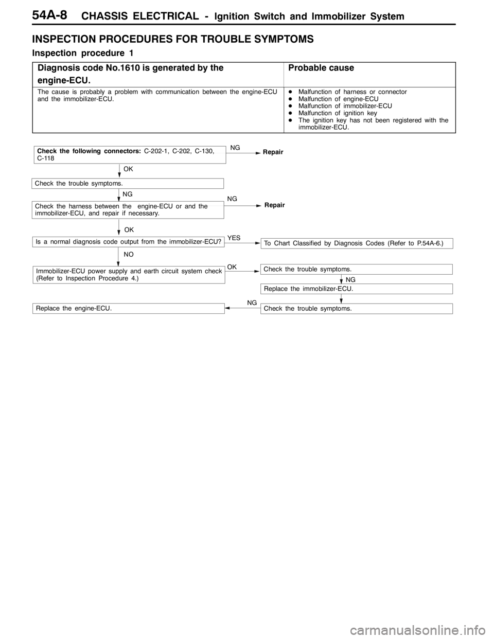
INSPECTION PROCEDURES FOR TROUBLE SYMPTOMS
Inspection procedure 1
Diagnosis code No.1610 is generated by the
engine-ECU.
Probable cause
The cause is probably a problem with communication between the engine-ECU
and the immobilizer-ECU.DMalfunction of harness or connector
DMalfunction of engine-ECU
DMalfunction of immobilizer-ECU
DMalfunction of ignition key
DThe ignition key has not been registered with the
immobilizer-ECU.
OKImmobilizer-ECU power supply and earth circuit system check
(Refer to Inspection Procedure 4.)
OK
Check the trouble symptoms.
NGRepair
NGCheck the following connectors:C-202-1, C-202, C-130,
C-118
Repair
NGCheck the harness between the engine-ECU or and the
immobilizer-ECU, and repair if necessary.
NG
Replace the immobilizer-ECU.
Check the trouble symptoms.
Check the trouble symptoms.Replace the engine-ECU.OK
Is a normal diagnosis code output from the immobilizer-ECU?
NOTo Chart Classified by Diagnosis Codes (Refer to P.54A-6.) YES
NG
Page 1329 of 1449

CHASSIS ELECTRICAL -Ignition Switch and Immobilizer System54A-9
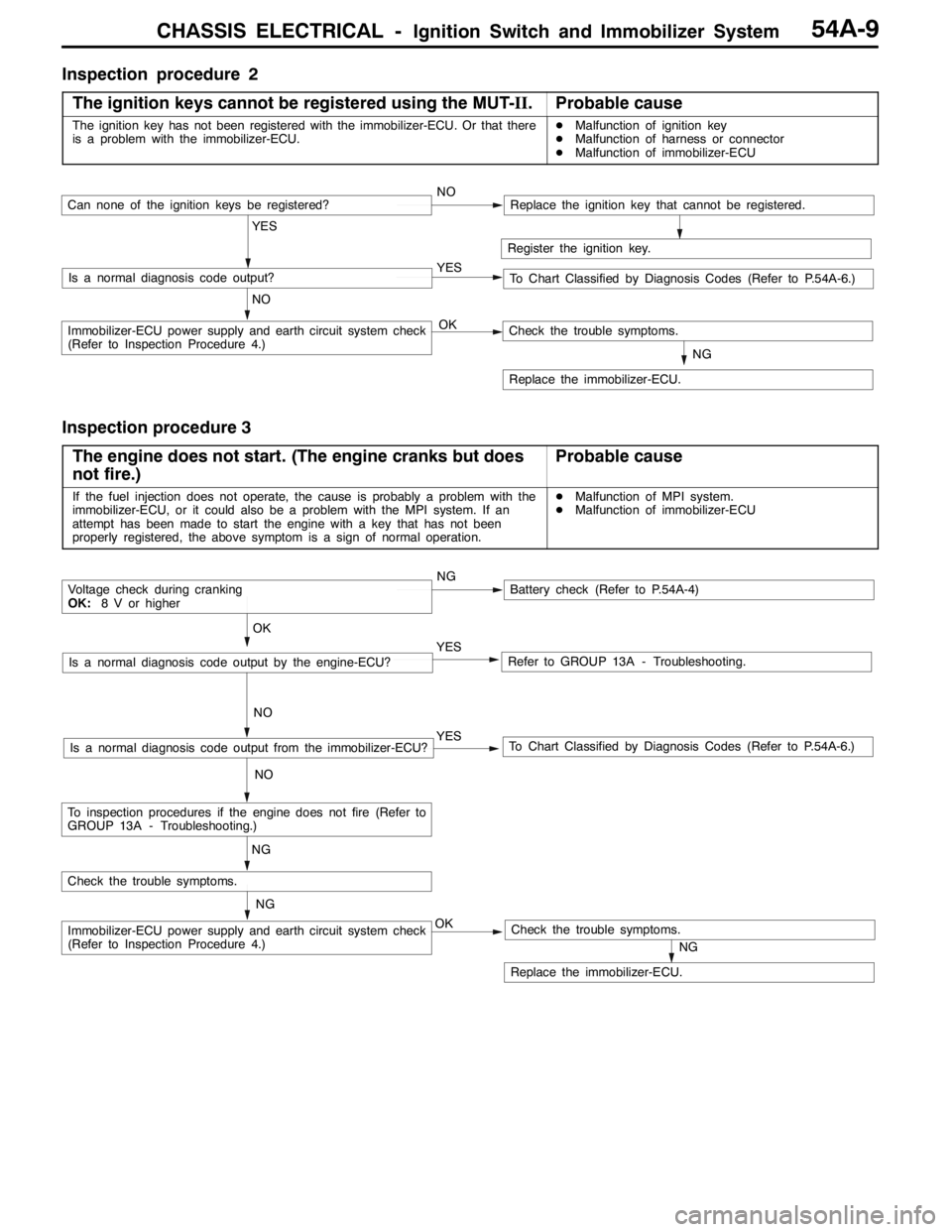
Inspection procedure 2
The ignition keys cannot be registered using the MUT-II.
Probable cause
The ignition key has not been registered with the immobilizer-ECU. Or that there
is a problem with the immobilizer-ECU.DMalfunction of ignition key
DMalfunction of harness or connector
DMalfunction of immobilizer-ECU
Register the ignition key.
YES
NO YESIs a normal diagnosis code output?
NOCan none of the ignition keys be registered?Replace the ignition key that cannot be registered.
To Chart Classified by Diagnosis Codes (Refer to P.54A-6.)
OKImmobilizer-ECU power supply and earth circuit system check
(Refer to Inspection Procedure 4.)
NG
Replace the immobilizer-ECU.
Check the trouble symptoms.
Inspection procedure 3
The engine does not start. (The engine cranks but does
not fire.)
Probable cause
If the fuel injection does not operate, the cause is probably a problem with the
immobilizer-ECU, or it could also be a problem with the MPI system. If an
attempt has been made to start the engine with a key that has not been
properly registered, the above symptom is a sign of normal operation.DMalfunction of MPI system.
DMalfunction of immobilizer-ECU
NGBattery check (Refer to P.54A-4)
YES
NO
Refer to GROUP 13A - Troubleshooting.YES
NO
To Chart Classified by Diagnosis Codes (Refer to P.54A-6.)Is a normal diagnosis code output from the immobilizer-ECU?
OK
Voltage check during cranking
OK:8 V or higher
Is a normal diagnosis code output by the engine-ECU?
NG
OKImmobilizer-ECU power supply and earth circuit system check
(Refer to Inspection Procedure 4.)
NG
Replace the immobilizer-ECU.
Check the trouble symptoms.
Check the trouble symptoms.
NG
To inspection procedures if the engine does not fire (Refer to
GROUP 13A - Troubleshooting.)