2007 MITSUBISHI LANCER EVOLUTION ignition
[x] Cancel search: ignitionPage 851 of 1449

MANUAL TRANSMISSION - On-vehicle Service22A-43
4. Set the gear to the 2nd gear or above, operate the MUT-II,
and check from the service data (Item No.09) that the
wheel speed is within 10 km/h to 20 km/h.
NOTE
(1) Set the steering wheel to the neutral position
(2) The ACD may continue operating (operation sounds
can be heard) when the steering wheel is steered,
this is not a system fault. In this case, set the steering
wheel to the neutral position, and perform the following
operations to stop the ACD.
DRelease the clutch.
DSet the gear to “N”.
DStop the engine
5. Perform the MUT-IIactuator test (Item No.05), and forcibly
drive the transfer.
NOTE
(1) The actuator test (Item No. 05: ACD Operation Check
Mode) is performed for 1 minute, after which it will
be cleared automatically. Drive can also be cleared
during forced driving using the clear key of the MUT-II.
(2) If the hydraulic unit function has been stopped by
fail-safe, the transfer cannot be forcibly driven.
6. Check that the front and rear wheel speeds satisfy the
following in the MUT-IIactuator test (Item No.05).
The front wheel will be faster than the back wheels by
more than 2 km/h.
NOTE
If the above are not satisfied, check the oil pressure as
the system may be faulty.
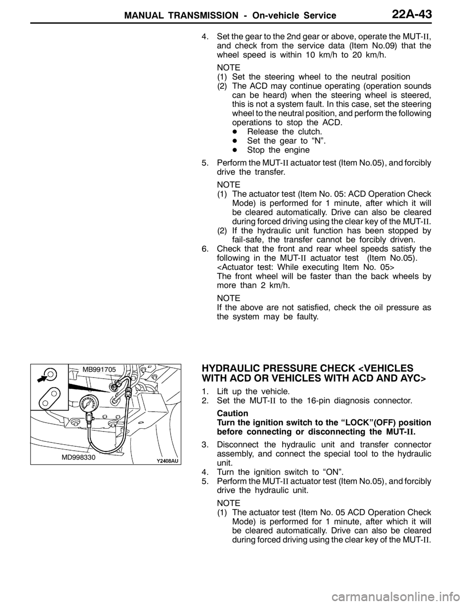
HYDRAULIC PRESSURE CHECK
1. Lift up the vehicle.
2. Set the MUT-IIto the 16-pin diagnosis connector.
Caution
Turn the ignition switch to the “LOCK”(OFF) position
before connecting or disconnecting the MUT-II.
3. Disconnect the hydraulic unit and transfer connector
assembly, and connect the special tool to the hydraulic
unit.
4. Turn the ignition switch to “ON”.
5. Perform the MUT-IIactuator test (Item No.05), and forcibly
drive the hydraulic unit.
NOTE
(1) The actuator test (Item No. 05 ACD Operation Check
Mode) is performed for 1 minute, after which it will
be cleared automatically. Drive can also be cleared
during forced driving using the clear key of the MUT-II.
MD998330
MB991705
Page 955 of 1449

REAR AXLE -Troubleshooting
ERASING THE DIAGNOSIS CODES
Connect the MUT-IIto the 16-pin diagnosis connector and
erase the diagnosis code. (Refer to GROUP 00 – How to
Use Troubleshooting/Inspection Service Points.)
Caution
Turn the ignition switch to the LOCK (OFF) position before
connecting or disconnecting the MUT-II.
INSPECTION CHART FOR DIAGNOSIS CODE
Diagnosis
code No.Diagnosis itemsReference page
12Power supply voltage (valve power supply) systemopen- or short-circuitRefer to
GROUP22
13Failsafe relay system
GROUP22.
21FR wheel speed sensor systemopen- or short-circuit
22FL wheel speed sensor systemopen- or short-circuit
23RR wheel speed sensor systemopen- or short-circuit
24RL wheel speed sensor systemopen- or short-circuit
25Wrong-diameter tire
26Wheel speed sensor (faulty output signal)
31Steer sensor (ST-1, ST-2, ST-N) systemopen- or short-circuit
32Steer sensor (ST-N) systemshort-circuit
33fixed
34Steer sensor (ST-1, ST-2) systemshort-circuit or output
fixed
41TPS systemopen-circuit or ground
42short-circuit
45Pressure sensor systemopen-circuit or ground
46open earth
47abnormal power supply
51G sensor (longitudinal) systemopen- or short-circuit
52defective sensor
56G sensor (lateral) systemopen- or short-circuit
57defective sensor
Page 956 of 1449

REAR AXLE -Troubleshooting
Diagnosis
code No.Reference page Diagnosis items
61Stop lamp switch systemopen-circuitRefer to
GROUP22
62ACD mode changeover switchstuck
GROUP22.
63Parking brake switch systemshort-circuit or not re-
turned
65ABS monitor systemopen-circuit or defective
ABS
71Proportioning valve
72Directional control valve (right) systemopen- or short-circuit27B-12
73Directional control valve (left) systemopen- or short-circuit27B-13
74Proportioning valve
GROUP22
81Electric pump relay systemopen- or short-circuit
GROUP22.
82electric pump malfunction
or pressure sensor defect
84AYC control error–
85ACD control errorRefer to
GROUP 22.
NOTE
Code No.84 is not a code number output due to malfunction, but a code number output when control
for the 4WD-ECU to protect the AYC is stopped in excessive driving. AYC control can be recovered
by turning the ignition switch ON to OFF to ON.
Page 960 of 1449

REAR AXLE -Troubleshooting
INSPECTION CHART FOR TROUBLE SYMPTOMS
Trouble symptomInspection
procedure No.Reference
page
Communication between MUT-IIand the whole system is not possible.1Refer to
GROUP22
Communication between MUT-IIand 4WD-ECU is not possible.2
GROUP22.
3 ACD mode indicator lamps do not light up when the ignition key is turned to “ON”
(engine stationary).3
3 ACD mode indicator lamps remain lit up after the engine has started.4
AYC is inoperative.
Unable to start or accelerate on slippery road surfaces.527B-14
Rear tires are noisy during low-speed cornering.
Vehicle skews.627B-15
Noise is produced from the torque transfer differential during turning.727B-15
INSPECTION PROCEDURE FOR TROUBLE SYMPTOMS
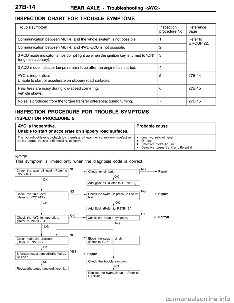
INSPECTION PROCEDURE 5
AYC is inoperative.
Unable to start or accelerate on slippery road surfaces.
Probable cause
The hydraulic oil level is probably low, there is an oil leak, the hydraulic unit is defective,
or the torque transfer differential is defective.DLow hydraulic oil level
DOil leak
DDefective hydraulic unit
DDefective torque transfer differential
NOTE
This symptom is limited only when the diagnosis code is correct.
NG
Replace the hydraulic unit. (Refer to
P.27B-61.)
NG
Add fluid. (Refer to P.27B-19.)
OKRepair
Check the trouble symptom.NO
Replace the torque transfer differential.
OK
Is foreign matter trapped in the hydrau-
lic line?YES
Repair
OK
Check the fluid level.
(Refer to P.27B-19.)Check the hydraulic pressure line for
leak.
OK
Add gear oil. (Refer to P.27B-16.)
OK
Check hydraulic pressure.
(Refer to P.27-21.)NGBleed the system of air.
(Refer to P.27-19.)
Check the gear oil level. (Refer to
P.27B-16.)NGCheck for oil leak.NG
Repair
Check the AYC for operation.
(Refer to P.27B-20.)Check the trouble symptom. OKOK
NGNormal
NGNG
Page 965 of 1449

REAR AXLE -On-vehicle Service27B-19
FLUID LEVEL CHECK
1. Remove the maintenance lid located in the luggage
compartment.
2.
If the vehicle has been run, leave it for 90 min. or more
in an ordinary temperature (10_C–30_C) to allow the
accumulator internal pressure to drop.
NOTE
If the ambient temperature is 10_C or less, allow more
time to leave the vehicle to stand idle.
Set MUT-IIto 16 pin diagnostic connector. Turn the ignition
switch to the ON position, operate MUT-II, drive the
hydraulic unit (item No.03) forcibly, release the pressure in
the accumulator.
Caution
Turn the ignition switch to the LOCK (OFF) position
before connecting or disconnecting the MUT-II.
NOTE
(1) To drive (oil level check mode) forcibly, turn the
directional valve of the hydraulic unit 20 turns from
side to side, release the differential automatically.
Drive can also be cleared forcibly using the Clear
key of MUT-II.
(2) If the function has been stopped by fail safe, the
hydraulic unit can not be cleared forcibly.
3. Check that the fluid level in the oil reservoir is in the
range between MAX and MIN.
4. If the fluid level is lower than MIN, add the specified
fluid.
Specified fluid: ATF-SP III
5. Reinstall the maintenance lid.
BLEEDING
1. Lift up the vehicle.
2. Set the MUT-IIto the 16-pin diagnosis connector.
Caution
Turn the ignition switch to the LOCK (OFF) position
before connecting or disconnecting the MUT-II.
3. Turn the ignition switch to the ON position.
4. Set the steering wheel in the straight-ahead position.
5. Operating the MUT-II, drive the hydraulic unit (item No.02)
forcibly.
NOTE
(1) Drive the bleeding mode forcibly for 5 minutes, release
the operation automatically. Drive can also be cleared
forcibly using the Clear key of MUT-II.
(2) If the function has been stopped by fail safe, the
hydraulic unit cannot be cleared forcibly.
Page 966 of 1449

REAR AXLE -On-vehicle Service27B-20
6. Remove the cap of the left bleeder screw on the torque
transfer differential and connect a vinyl hose.
7. Gradually turn the steering wheel clockwise from the
straight-ahead position. At this time, loosen the left bleeder
screw and check that fluid is discharged with air.
8. After air has been completely discharged, tighten bleeder
screw and turn the steering wheel in the straight-ahead
position.
Caution
While the system is being bled of air, add fluid as
necessary to ensure that it is left in the oil reservoir
during the entire procedure.
9. Repeat steps 6 and 7 two to three times until no air
bubbles are recognized in the fluid that comes out. Then,
tighten the bleeder screw to the specified torque.
Tightening torque: 9±1 N·m
10. Perform steps 5 through 8 for the right bleeder screw.
Note, however, that the steering wheel should be turned
conterclockwise.
11. When removing the hydraulic unit, bleed the fluid line
in ACD side. (Refer to GROUP 22 – On-vehicle Service.)
12. After the system has been completely bled of air, check
for the fluid level. (Refer to P. 27B-19.)
Caution
If the system is not completely bled of air, the hydraulic
unit could generate noise, degrading pump durability.
AYC OPERATION CHECK
1. Lift up the vehicles.
2. Set the MUT-IIto the 16-pin diagnosis connector.
Caution
Turn the ignition switch to the LOCK (OFF) position
before connecting or disconnecting the MUT-II.
3. Start the engine.
4. Set the gear to the 2nd gear or above, operate MUT-II,
and check from the service data (Item No.09) that the
wheel speed is within 10 km/h to 20 km/h.
NOTE
(1) Set the steering wheel to the neutral position.
(2) When turning the steering wheel, AYC operates
continually (operation sound from the torque transfer
differential), but it is not system fault. In this case,
set the steering wheel to the neutral position, and
perform the following operations in order to stop the
ACD.
DRelease the clutch.
DSet the gear to ”Neutral”.
DStop the engine.
Bleeder
screw
Vinyl hose
Page 967 of 1449

REAR AXLE -On-vehicle Service27B-21
5. Operate the MUT-II, drive the torque transfer differential
(item No.06 and 07) forcibly.
NOTE
(1) Drive the clutch operating mode forcibly for 1 minutes,
release the operation automatically. Drive can also
be cleared forcibly using the Clear key of MUT-II.
(2) If the hydraulic unit function has been stopped by
fail-safe, the torque transfer differential cannot be
forcibly driven.
6. Operating the MUT-II, by service data (item no.07 and 08),
check the condition of the wheel speed below.
The left rear wheel is faster 2km/h than right rear wheel.
The right rear wheel is faster 2km/h than left rear wheel.
NOTE
If the above are not satisfied, check the oil pressure as
the system may be faulty.
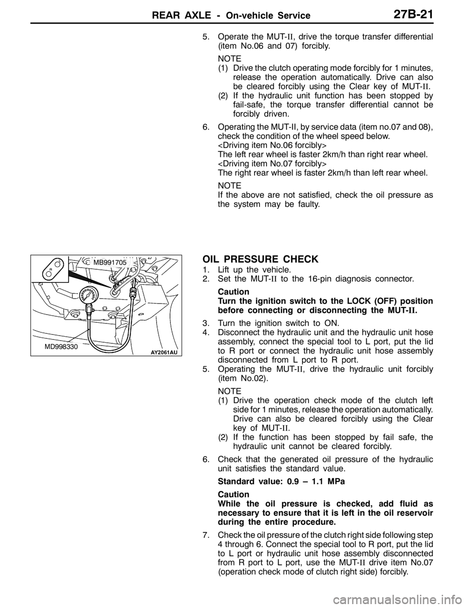
OIL PRESSURE CHECK
1. Lift up the vehicle.
2. Set the MUT-IIto the 16-pin diagnosis connector.
Caution
Turn the ignition switch to the LOCK (OFF) position
before connecting or disconnecting the MUT-II.
3. Turn the ignition switch to ON.
4. Disconnect the hydraulic unit and the hydraulic unit hose
assembly, connect the special tool to L port, put the lid
to R port or connect the hydraulic unit hose assembly
disconnected from L port to R port.
5. Operating the MUT-II, drive the hydraulic unit forcibly
(item No.02).
NOTE
(1) Drive the operation check mode of the clutch left
side for 1 minutes, release the operation automatically.
Drive can also be cleared forcibly using the Clear
key of MUT-II.
(2) If the function has been stopped by fail safe, the
hydraulic unit cannot be cleared forcibly.
6. Check that the generated oil pressure of the hydraulic
unit satisfies the standard value.
Standard value: 0.9 – 1.1 MPa
Caution
While the oil pressure is checked, add fluid as
necessary to ensure that it is left in the oil reservoir
during the entire procedure.
7. Check the oil pressure of the clutch right side following step
4 through 6. Connect the special tool to R port, put the lid
to L port or hydraulic unit hose assembly disconnected
from R port to L port, use the MUT-IIdrive item No.07
(operation check mode of clutch right side) forcibly.
MD998330
MB991705
Page 1022 of 1449

POWER PLANT MOUNT - Crossmember32-8
CROSSMEMBER
REMOVAL AND INSTALLATION
Caution
1. Before removing the steering wheel and air bag module assembly, always refer to GROUP
52B - Service Precautions, Air bag Module and Clock Spring. Also, set the front wheels so
that they are facing straight forward, and remove the ignition key. If you fail to do this, the
SRS clock spring will be damaged, causing the SRS air bag to be inoperative and serious
injury.
2. *
1: Indicates parts which should be initially tightened, and then fully tightened after placing
the vehicle horizontally and loading the full weight of the engine on the vehicle body.
3. *
2: Indicates parts which should be temporarily tightened, and then fully tightened with the
vehicle on the ground in the unladen condition.
Caution
If the vehicle is equipped the Brembo disc brake, during maintenance, take care not to contact
the parts or tools to the caliper because the paint of caliper will be scratched.
Pre-removal Operations
DUnder Cover Removal
(Refer to GROUP 51 - Front Bumper.)
DCentermember, Crossmember Bar Removal
(Refer to P.32-6.)
DFront Exhaust Pipe Removal
(Refer to GROUP 15.)
DSteering Wheel Air Bag Module Assembly Removal
(Refer to GROUP 37A.)
DPower Steering Fluid Draining
(Refer to GROUP 37A - On-vehicle Service.)Post-installation Operations
DCentermember, Crossmember Bar Installation
(Refer to P.32-6.)
DFront Exhaust Pipe Installation
(Refer to GROUP 15.)
DSteering Wheel Air Bag Module Assembly
Installation (Refer to GROUP 37A.)
DPower Steering Fluid Supplying
(Refer to GROUP 37A - On-vehicle Service.)
DPower Steering Fluid Line Bleeding
(Refer to GROUP 37A - On-vehicle Service.)
DPress the dust cover with a finger to check whether
the dust cover is cracked or damaged.
DChecking Steering Wheel Position with Wheels
Straight Ahead
DFront Wheel Alignment Check and Adjustment
(Refer to GROUP 37A - On-vehicle Service.)
DUnder Cover Installation
(Refer to GROUP 51 - Front Bumper.)