2007 MITSUBISHI LANCER EVOLUTION ignition
[x] Cancel search: ignitionPage 840 of 1449

MANUAL TRANSMISSION - Troubleshooting
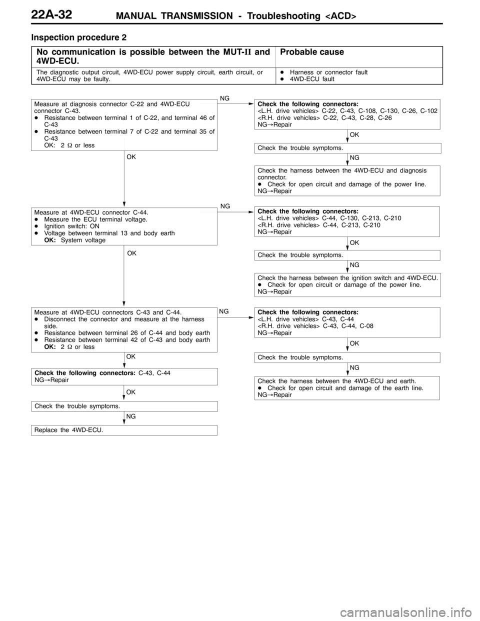
Inspection procedure 2
No communication is possible between the MUT-IIand
4WD-ECU.
Probable cause
The diagnostic output circuit, 4WD-ECU power supply circuit, earth circuit, or
4WD-ECU may be faulty.DHarness or connector fault
D4WD-ECU fault
NG OK OK
NG OK OK
NG OK
OK
NG
NG
NG
Check the trouble symptoms.
Check the harness between the 4WD-ECU and earth.
DCheck for open circuit and damage of the earth line.
NG→Repair
Check the following connectors:
NG→Repair
Check the harness between the ignition switch and 4WD-ECU.
DCheck for open circuit or damage of the power line.
NG→Repair
Check the trouble symptoms.
Measure at 4WD-ECU connector C-44.
DMeasure the ECU terminal voltage.
DIgnition switch: ON
DVoltage between terminal 13 and body earth
OK:System voltageCheck the following connectors:
NG→Repair
Check the harness between the 4WD-ECU and diagnosis
connector.
DCheck for open circuit and damage of the power line.
NG→Repair
Check the trouble symptoms.
Measure at diagnosis connector C-22 and 4WD-ECU
connector C-43.
DResistance between terminal 1 of C-22, and terminal 46 of
C-43
DResistance between terminal 7 of C-22 and terminal 35 of
C-43
OK: 2Ωor lessCheck the following connectors:
NG→Repair
Replace the 4WD-ECU.
Measure at 4WD-ECU connectors C-43 and C-44.
DDisconnect the connector and measure at the harness
side.
DResistance between terminal 26 of C-44 and body earth
DResistance between terminal 42 of C-43 and body earth
OK:2Ωor less
NG OK
Check the trouble symptoms.
Check the following connectors:C-43, C-44
NG→Repair
Page 841 of 1449

MANUAL TRANSMISSION - Troubleshooting
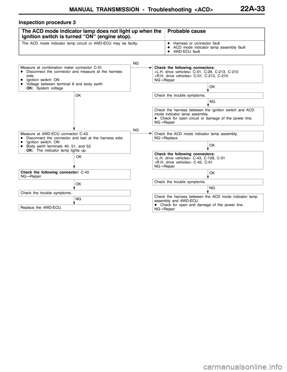
Inspection procedure 3
The ACD mode indicator lamp does not light up when the
ignition switch is turned “ON” (engine stop).
Probable cause
The ACD mode indicator lamp circuit or 4WD-ECU may be faulty.DHarness or connector fault
DACD mode indicator lamp assembly fault
D4WD-ECU fault
OK OK OKOK
NG
OK
NG
NG
NG
Check the harness between the ACD mode indicator lamp
assembly and 4WD-ECU.
DCheck for open and damage of the power line.
NG→Repair
Replace the 4WD-ECU.
Measure at 4WD-ECU connector C-43.
DDisconnect the connector and test at the harness side.
DIgnition switch: ON
DBody earth terminals 40, 51, and 52.
OK:The indicator lamp lights up.
Check the trouble symptoms.
Measure at combination meter connector C-01.
DDisconnect the connector and measure at the harness
side.
DIgnition switch: ON
DVoltage between terminal 9 and body earth
OK:System voltageCheck the following connectors:
NG→Repair
Check the trouble symptoms.
Check the ACD mode indicator lamp assembly.
NG→Replace
Check the harness between the ignition switch and ACD
mode indicator lamp assembly.
DCheck for open circuit or damage of the power line.
NG→Repair
Check the following connectors:
NG→Repair
OK
NG
Check the trouble symptoms.
Check the following connector:C-43
NG→Repair
Page 843 of 1449

MANUAL TRANSMISSION - Troubleshooting
DATA LIST REFERENCE TABLE
Item
no.Check itemCheck conditionNormal conditions
01Wheel speed sensor
play and MUT-IIdis-
lth02Wheel speed sensor
py
play match.
03Wheel speed sensor
04Wheel speed sensor
05Wheel speed sensor
06Wheel speed sensor
07Wheel speed sensor
08Wheel speed sensor
09Vehicle speed
10Battery voltageIgnition switch: ONSystem voltage
11Proportional valve cur-
rent
12Proportional valve cur-
rent
13TPS voltageIgnition switch: ON
Engine: StoppedAccelerator pedal: Full
closed535 - 735 mV
Engine:Stopped
Accelerator pedal: PressGradually rises from
the above value
Accelerator pedal: Full
throttle4,500 - 5,000 mV
14Longitudinal G sensor
voltageIgnition switch: ONVehicle stopped (horizon-
tal) state2.4 - 2.6 V
g
Actual drivingThe displayed value
increases and de-
creases mainly around
2.5 V.
15Lateral G sensor volt-
ageIgnition switch: ONVehicle stopped (horizon-
tal) state2.4 - 2.6 V
g
Perform actual drivingThe displayed value
increases and de-
creases mainly around
2.5 V.
16Steering operation
angleIgnition switch: ONSteering wheel: Steer by 90
degrees to the rightR90 deg
g
Steering wheel: Steer by 90
degrees to the leftL90 deg
17Steering angle velocityIgnition switch: ONSteering wheel: No steering0 deg/sggyg
Steering wheel: SteerThe display changes
according to the revolu-
tion speed.
18Pressure sensorDuring electric pump motor operations1.0 - 1.6 MPa
Page 844 of 1449

MANUAL TRANSMISSION - Troubleshooting
Item
no.Normal conditions Check condition Check item
19Pressure sensor power
supplyIgnition switch: ONApprox.5 V
20Valve power supplyIgnition switch: ONSystem voltage
21Steering wheel sensor
voltage
are displayed alter-
nately.
22Steering wheel sensor
voltage
are displayed alter-
nately.
23Steering wheel sensor
ltSTN
Ignition switch: ONSteering wheel: Neutral1-2Vg
voltage
g
Steering wheel: Turn2.5 - 4.5 V
51Idle switchIgnition switch: ONAccelerator pedal: Full
closedON
Accelerator pedal: PressOFF
52Steering wheel sensor
STN
Ignition switch: ONsteering wheel: NeutralONg
g
Steering wheel: Turn from
the neutral positionOFF
53Steering wheel sensor
played alternaltely.
54Steering wheel sensor
played alternately
55Steering wheel sensor
learning
tral position learning exe-
cutedON
Steering wheel sensor neu-
tral position learning unex-
ecutedOFF
56Stop lamp switchIgnition switch: ONBrake pedal: DepressONppg
Engine: StoppedBrake pedal: ReleaseOFF
57Motor monitorElectric pump motor is currently operatingON
Electric pump motor is currently not operatingOFF
58Oil pressure stateElectric pump motor is currently operatingLOWp
Electric pump motor is currently not operatingHIGH
59Directional valve
Ri ht
AYC clutch right side is currently operatingON
60Directional valve
Lft
AYC clutch left side is currently operatingON
61ABS monitorABS is currently operatingON
ABS is currently not operatingOFF
62Parking brake switchIgnition switch: ONParking brake lever: PullONgg
Engine:StoppedParking brake lever: Re-
leaseOFF
63ACD mode switchIgnition switch: ONACD mode switch: PressONg
Engine:StoppedACD mode switch: ReleaseOFF
Page 846 of 1449

MANUAL TRANSMISSION - Troubleshooting
CHECK AT 4WD-ECU TERMINALS
NOTE:
1. *1indicates the eliminated terminal when only ACD is installed.
2. *2indicates the terminal added when only ACD is installed.
Termi-
nal no.
Check itemCheck conditionNormal state
1Proportional valve
Operate the Proportional
valveintheactuatortest
While executing the actuator testSystem voltage
(Item No.01).
3*1Proportional valve
Operate the Proportional
valveintheactuatortest
While executing the actuator testSystem voltage
(Item No. 02).
6Wheel speed sensor
FL
Vehicle is stopping1 V or lessp
7Wheel speed sensor
RR
Vehicle is stopping1 V or lessp
8Wheel speed sensor
RL
Vehicle is stopping1 V or lessp
9Wheel speed sensor
FR
Vehicle is stopping1 V or lessp
10Pressure sensor earthAny time1 V or less
11Lateral G sensorIgnition switch: ON
Vehicle horizontal state2.4 - 2.6 V
134WD-ECU power sup-
l
Ignition switch: OFF0Vpp
plyIgnition switch: ONSystem voltage
14*1Directional valve
valve
actuator test (Item No.
07)After completing the actuator test1 V or less
15*1Directional valve
Operate the directional
valve
While executing the actuator testSystem voltage
tor test (Item No. 06)After completing the actuator test1 V or less
16Electric pump relay
l
When the electric pump motor is not operating0Vppy
power supplyWhile the electric pump motor is operatingSystem voltage
19*2Wheel speed sensor
earth
20*2Wheel speed sensor
earth
21*2Wheel speed sensor
earth
22*2Wheel speed sensor
earth
23Longitudinal G sensorIgnition switch: ON
Vehicle horizontal state2.4 - 2.6 V
Page 847 of 1449

MANUAL TRANSMISSION - Troubleshooting
Termi-
nal no.Normal state Check condition Check item
24*2Longitudinal G sensor
earth, lateral G sensor
earthAny time1 V or less
26ECU earthAny time1 V or less
31ECU backup power
supplyAny timeSystem voltage
32Pressure sensorIgnition switch: ON0.5 - 1.5 V
33Steering wheel sensor
4.5 V flushing
34Steering wheel sensor
4.5 V flushing
35Diagnosis data input/
output--
36Idle switchIgnition switch: ONAccelerator pedal: Full closed1 V or lessg
Accelerator pedal: Depress4.5 - 5.0 V
37Parking brake switchIgnition switch: ONParking brake lever: Pull1 V or lessgg
Parking brake lever: ReleaseSystem voltage
38Stop lamp switchIgnition switch: ONBrake pedal: DepressSystem voltageppg
Brake pedal: Release1 V or less
39TPSIgnition switch: ONAccelerator pedal: Full closed0.5 - 0.7 Vg
Accelerator pedal: Full throttle4.5 - 5.5 V
40ACD mode indicator
lamp
TARMAC0V
p
ACD mode indicator lamp position:
Except for aboveApprox. 10.5 V
42ECU earthAny time1 V or less
43Pressure sensor earthAny time1 V or less
44Steering wheel sensor
STN
Ignition switch: ONSteering wheel: Neutral1-2Vg
g
Steering wheel: Turn from the
neutral position2.5 - 4.5 V
46Diagnosis control--
47ACD mode switchIgnition switch: ONSwitch: PressSystem voltageg
Switch: Release0V
49*1ABS monitorWith ABS not activeSystem voltage
With ABS active1.5 V or less
50*2EarthAny time1 V or less
51ACD mode indicator
lamp
SNOW0V
p
ACD mode indicator lamp position:
Except for aboveApprox. 10.5 V
52ACD mode indicator
lamp
GRAVEL0V
p
ACD mode indicator lamp position:
Except for aboveApprox. 10.5 V
Page 849 of 1449

MANUAL TRANSMISSION - On-vehicle Service22A-41
4. Fill with specified oil till the level comes to the lower portion
of oil filler plug hole.
Specified transfer oil:
MITSUBISHI Genuine Gear Oil Part No.8149630
EX, CASTROL HYPOY LS (GL-5, SAE 90),
SHELL-LSD (GL-5, SAE 80W - 90) or equivalent
Quantity:
0.55 L
0.6 L
5. Tighten the oil filler plug to the specified torque.
Tightening torque: 32±2 N·m
FLUID CHECK
1. Remove the maintenance lid located in the luggage
compartment.
2.
If the vehicle has been run, leave it for 90 min. or more
in an ordinary temperature (10_C–30_C) to allow the
accumulator internal pressure to drop.
NOTE
If the ambient temperature is 10_C or less, allow more
time to leave the vehicle to stand idle.
Set the MUT-IIto the 16-pin diagnosis connector. Turn ON
the ignition switch, perform MUT-IIactuator test (Item
No.03), forcibly drive the hydraulic unit and remove the
pressure in the accumulator.
Caution
Turn the ignition switch to the “LOCK”(OFF) position
before connecting or disconnecting the MUT-II.
NOTE
(1) In the actuator test (Item No. 03: Oil Level Check
Mode), the directional valve of the hydraulic unit is
moved to the left and right for 20 times, and then
the differential is cleared automatically. Drive can also
be cleared forcibly using the Clear key of the MUT-II.
(2) If the function has been stopped by fail-safe, the
hydraulic unit cannot be cleared forcibly.
3. Check that the fluid level in the oil reservoir is in the
range between MAX and MIN.
4. If the fluid level is lower than MIN, add the specified
fluid.
Specified fluid: Dia Queen ATF SP III
5. Reinstall the maintenance lid.
Page 850 of 1449

MANUAL TRANSMISSION - On-vehicle Service22A-42
BLEEDING
1. Lift up the vehicle.
2. Set the MUT-IIto the 16-pin diagnosis connector.
Caution
Turn the ignition switch to the “LOCK”(OFF) position
before connecting or disconnecting the MUT-II.
3. Turn the ignition switch to the “ON” position.
4. Set the steering wheel in the straight-ahead position.
5. Perform the MUT-IIactuator test (Item No.02), and forcibly
drive the hydraulic unit.
NOTE
(1) The actuator test (Item No.01: Bleeding Mode) will
be performed for 5 minutes, after which it will be
cleared automatically. Drive can also be cleared during
forced driving using the clear key of the MUT-II.
(2) If the hydraulic unit function has been stopped by
fail-safe, the hydraulic unit cannot be forcibly driven.
6. Remove the cap of the bleeder screw on the transfer,
and connect the vinyl hose.
7
.Slowly turn the steering wheel to the left or right from
the neutral state. Loosen the bleeder screw, and check
that air is discharged together with the fluid.
8
.After the air is discharged, tighten the bleeder screw,
and return the steering wheel to the neutral state.
Caution
During bleeding, replenish the fluid so that some
always remains in the oil reservoir.
9. Repeat steps 6 and 7 several 2 to 3 times, and after
checking that no more air mixes in, tighten the bleeder
screw at the specified torque.
Tightening torque: 5±1 N·m
10. After bleeding, check the fluid level. (Refer to P. 22A-41.)
Caution
If bleeding is not performed completely, noise may
be produced from the hydraulic unit, or the durability
of the pump, etc. may drop.
11. On vehicles with AYC, perform bleeding when the
hydraulic unit is removed. (Refer to GROUP 27B -
On-vehicle Service.)
ACD OPERATION CHECK
1. Lift up the vehicle.
2
.Set the MUT-IIto the 16-pin diagnosis connector.
Caution
Turn the ignition switch to the “LOCK”(OFF) position
before connecting or disconnecting the MUT-II.
3. Start the engine.
Bleeder screw
Front exhaust pipe