Page 766 of 1449
ENGINE ELECTRICAL -Ignition System16-34
IGNITION COIL
REMOVAL AND INSTALLATION
Pre-removal and Post-installation Operation
Center Cover Removal and Installation (Refer to GROUP 11A - Camshaft and Camshaft Oil Seal.)
10±2 N·m
12
25±4 N·m
3
4
14
5
10±2 N·m
Removal steps
1. Ignition coil connector
2. Spark plug cable No.1
3. Spark plug cable No.34. Ignition coil
5. Spark plug
Page 767 of 1449
ENGINE ELECTRICAL -Ignition System16-35
CAMSHAFT POSITION SENSOR
REMOVAL AND INSTALLATION
1 2
3
8.8±1.0 N·m
Removal steps
1. Camshaft position sensor connector
2. Camshaft position sensor
3. O-ring
CRANK ANGLE SENSOR
REMOVAL AND INSTALLATION
Caution
If the vehicle is equipped with the Brembo disc brake, during maintenance, take care not to contact
the parts or tools to the caliper because the paint of caliper will be scratched.
Pre-removal and Post-installation Operation
DCenter Cover Removal and Installation (Refer to GROUP 11A - Camshaft and Camshaft Oil Seal.)
DTiming Belt Removal and Installation (Refer to GROUP 11A.)
DReserve Tank Removal and Installation (Refer to GROUP 14 - Radiator.)
Page 768 of 1449
ENGINE ELECTRICAL -Ignition System16-36
12
3
8.8±1.0 N·m
4 5
6 7
8.8±1.0 N·m49±9 N·m
49±9 N·m40±5 N·m 12±2 N·m
22±4 N·m
22±4 N·m
12±2 N·m
22±4 N·m
Removal steps
1. Power steering oil pressure switch
connector
2. Heat protector
AA"3. Power steering oil pump, bracket and
oil reservoir assembly4. Power steering oil pump bracket
5. Crank angle sensor connector
6. Crank angle sensor
7. Connector bracket
REMOVAL SERVICE POINT
AA"POWER STEERING OIL PUMP, BRACKET AND
OIL RESERVOIR ASSEMBLY REMOVAL
Remove the power steering oil pump, bracket and oil reservoir
assembly with the hose attached from the bracket.
NOTE
Tie the removed oil pump with a rope and set aside where
they cannot hinder the removal of the power steering oil pump
bracket.
Page 769 of 1449
ENGINE ELECTRICAL -Ignition System16-37
DETONATION SENSOR
REMOVAL AND INSTALLATION
Caution
Do not give any impact during removal and installation of detonation sensor.
Pre-removal and Post-installation Operation
Intake Manifold Stay Removal and Installation (Refer to GROUP 15 - Intake Manifold.)
1
2
23±2 N·m
Removal steps
1. Detonation sensor connector
AA""AA2. Detonation sensor
REMOVAL SERVICE POINT
AA"DETONATION SENSOR REMOVAL
INSTALLATION SERVICE POINT
"AADETONATION SENSOR INSTALLATION
MD998773
Page 772 of 1449

ENGINE AND EMISSION CONTROL -Engine Control System17-2
ENGINE CONTROL SYSTEM
GENERAL INFORMATION
A cable-type accelerator mechanism and a
suspended-type pedal have been adopted.
SERVICE SPECIFICATIONS
ItemsStandard value
Accelerator cable play mm1-2
Engineidlespeedr/min850±50Engineidle speed±/min850±50
ON-VEHICLE SERVICE
ACCELERATOR CABLE CHECK AND
ADJUSTMENT
1. Turn A/C and lamps OFF.
Inspect and adjust at no load.
2. Warm engine until stabilized at idle.
3. Confirm idle speed is at prescribed value.
Standard value: 850±50 r/min
4. Stop engine (ignition switch OFF).
5. Confirm there are no sharp bends in accelerator cable.
6. Check inner cable for correct slack.
Standard value: 1 - 2 mm
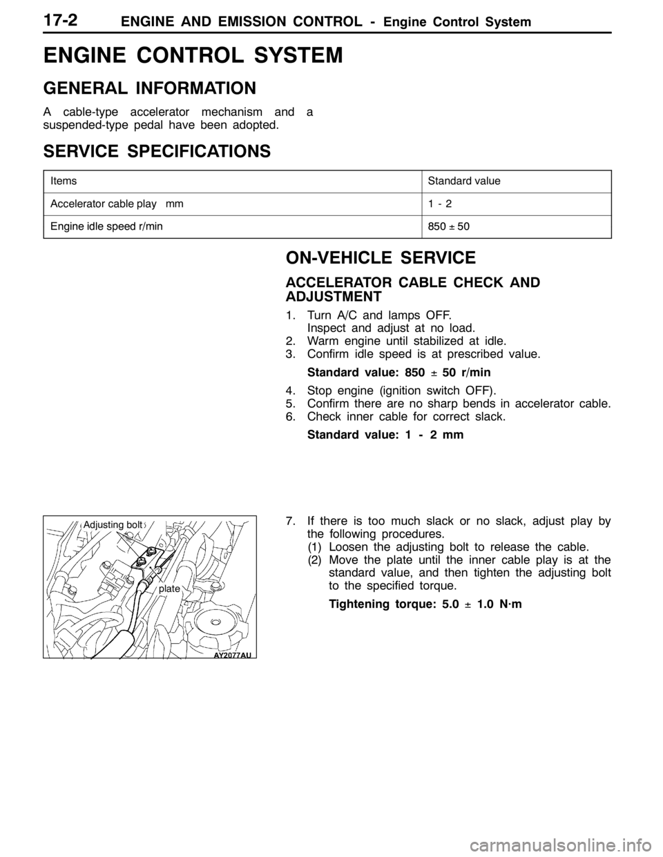
7. If there is too much slack or no slack, adjust play by
the following procedures.
(1) Loosen the adjusting bolt to release the cable.
(2) Move the plate until the inner cable play is at the
standard value, and then tighten the adjusting bolt
to the specified torque.
Tightening torque: 5.0±1.0 N·m
plate
Adjusting bolt
Page 813 of 1449

MANUAL TRANSMISSION - Troubleshooting 22A-5
TROUBLESHOOTING
BASIC TROUBLESHOOTING CONDITIONS
Refer to GROUP 00 - How to Use Troubleshooting/Inspection Service Points.
NOTE
Before starting the troubleshooting procedure, make sure that the following items have been checked
okay.
DIs the appropriate steering wheel installed at the center of the steering column shaft correctly?
DAre the tire, wheel size, specifications, air pressure, balance, and wear state normal?
DIs the wheel alignment normal?
DHas the engine, suspension, etc. been remodeled in such a way that it will affect the ACD and AYC
systems?
DIAGNOSIS FUNCTION
READING DIAGNOSIS CODE
Read a diagnosis code by the MUT-IIor ACD mode indicator
lamp. (Refer to GROUP 00 - How to Use Troubleshooting/
Inspection Service Points.)
NOTE
Connect the MUT-IIto the diagnosis connector (16-pin).
ERASING DIAGNOSIS CODES
When using the MUT-II
Connect the MUT-IIto the diagnosis connector (16-pin) and
erase the diagnosis code.
Caution
Turn the ignition switch to the “LOCK”(OFF) position
before connecting or disconnecting the MUT-II.
ACDmode indicator lamp
Page 815 of 1449
MANUAL TRANSMISSION - Troubleshooting 22A-7
Diagnosis
code No.Reference page Diagnosis items
81Electric pump relay systemopen circuit or short-circuit22A-29
82electric pump malfunction
or pressure sensor defect22A-30
84AYC control errorRefer to
GROUP 27B.
85ACD control error-
NOTE
Code No.85 is not a code number output due to malfunction, but a code number output when control
for the 4WD-ECU to protect the ACD is stopped in excessive driving. ACD control can be recovered
by turning the ignition switch ON to OFF to ON.
Page 816 of 1449

MANUAL TRANSMISSION - Troubleshooting 22A-8
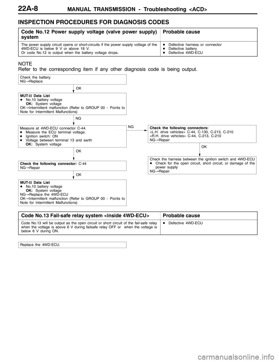
INSPECTION PROCEDURES FOR DIAGNOSIS CODES
Code No.12 Power supply voltage (valve power supply)
systemProbable cause
The power supply circuit opens or short-circuits if the power supply voltage of the
4WD-ECU is below 9 V or above 18 V.
Or code No.12 is output when the battery voltage drops.DDefective harness or connector
DDefective battery
DDefective 4WD-ECU
NOTE
Refer to the corresponding item if any other diagnosis code is being output.
OKOK
NG
NG
OK
Check the battery.
NG→Replace
Measure at 4WD-ECU connector C-44.
DMeasure the ECU terminal voltage.
DIgnition switch: ON
DVoltage between terminal 13 and earth
OK:System voltageCheck the following connectors:
C-44, C-130, C-213, C-210
C-44, C-213, C-210
NG→Repair
MUT-IIData List
DNo.10 battery voltage
OK:System voltage
OK→Intermittent malfunction (Refer to GROUP 00 - Points to
Note for Intermittent Malfunctions)
OK
Check the following connector:C-44
NG→Repair
MUT-IIData List
DNo.10 battery voltage
OK:System voltage
NG→Replace the 4WD-ECU
OK→Intermittent malfunction (Refer to GROUP 00 - Points to
Note for Intermittent Malfunctions)
Check the harness between the ignition switch and 4WD-ECU
DCheck for the open circuit, short circuit, or damage of the
power supply
NG→Repair
Code No.13 Fail-safe relay system Probable cause
Code No.13 will be output as the open circuit or short circuit of the fail-safe relay
when the voltage is above 6 V during failsafe relay OFF or when the voltage is
below 6 V during ON.DDefective 4WD-ECU
Replace the 4WD-ECU.