2007 MITSUBISHI LANCER EVOLUTION ignition
[x] Cancel search: ignitionPage 660 of 1449
MPI -On-vehicle Service13A-128
6. If not within the standard value range, turn the speed
adjusting screw to make the necessary adjustment.
7. Press the MUT-IIclear key, and release the idle speed
control servo from the Actuator test mode.
NOTE
Unless the idle speed control servo is released, the
Actuator test mode will continue 27 minutes.
8. Turn the ignition switch to “LOCK” (OFF) position.
9. Disconnect the MUT-II.
10. Start the engine again and let it run at idle speed for
approximately 10 minutes; check that the idling condition
is normal.
FUEL PRESSURE TEST
1. Release residual pressure from the fuel pipe line to prevent
fuel gush out. (Refer to P.13A-125.)
2. Disconnect the high-pressure fuel hose at the delivery
pipe side.
Caution
Cover the hose connection with rags to prevent splash
of fuel that could be caused by some residual pressure
in the fuel pipe line.
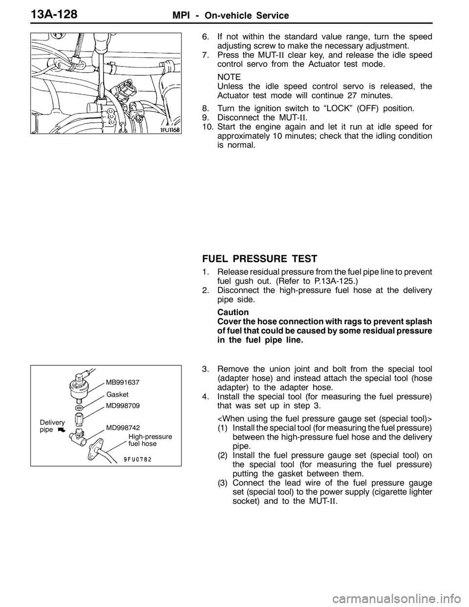
3. Remove the union joint and bolt from the special tool
(adapter hose) and instead attach the special tool (hose
adapter) to the adapter hose.
4. Install the special tool (for measuring the fuel pressure)
that was set up in step 3.
(1) Install the special tool (for measuring the fuel pressure)
between the high-pressure fuel hose and the delivery
pipe.
(2) Install the fuel pressure gauge set (special tool) on
the special tool (for measuring the fuel pressure)
putting the gasket between them.
(3) Connect the lead wire of the fuel pressure gauge
set (special tool) to the power supply (cigarette lighter
socket) and to the MUT-II.
MB991637
Gasket
MD998709
MD998742
High-pressure
fuel hose
Delivery
pipe
Page 661 of 1449
MPI -On-vehicle Service13A-129
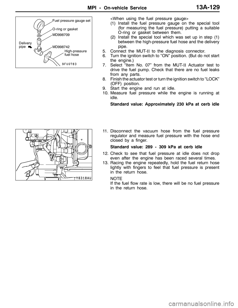
(1) Install the fuel pressure gauge on the special tool
(for measuring the fuel pressure) putting a suitable
O-ring or gasket between them.
(2) Install the special tool which was set up in step (1)
between the high-pressure fuel hose and the delivery
pipe.
5. Connect the MUT-IIto the diagnosis connector.
6. Turn the ignition switch to “ON” position. (But do not start
the engine.)
7. Select “Item No. 07” from the MUT-IIActuator test to
drive the fuel pump. Check that there are no fuel leaks
from any parts.
8. Finish the actuator test or turn the ignition switch to “LOCK”
(OFF) position.
9. Start the engine and run at idle.
10. Measure fuel pressure while the engine is running at
idle.
Standard value: Approximately 230 kPa at cerb idle
11. Disconnect the vacuum hose from the fuel pressure
regulator and measure fuel pressure with the hose end
closed by a finger.
Standard value: 289 - 309 kPa at cerb idle
12. Check to see that fuel pressure at idle does not drop
even after the engine has been raced several times.
13. Racing the engine repeatedly, hold the fuel return hose
lightly with fingers to feel that fuel pressure is present
in the return hose.
NOTE
If the fuel flow rate is low, there will be no fuel pressure
in the return hose.Fuel pressure gauge set
O-ring or gasket
MD998709
MD998742
High-pressure
fuel hose
Delivery
pipe
Page 663 of 1449

MPI -On-vehicle Service13A-131
COMPONENT LOCATION
NameSymbolNameSymbol
A/C relayJFuel pump relay 1, 2Q
A/C switchTFuel pump relay 3H
Air flow sensor (integrated intake air tempera-
ture sensor and barometric pressure sensor)OFuel pump resistorH
Camshaft position sensorNIdle speed control servo (stepper motor)G
Crank angle sensorKIgnition coil (integrated power transister)M
Detonation sensorEInjectorC
Diagnosis connectorSOxygen sensor (front)L
EGR control solenoid valveDOxygen sensor (rear)X
Engine control relayIPower steering fluid pressure switchA
Engine coolant temperature sensorNResistor (for injector)H
Engine warning lamp (check engine lamp)RSecondary air control solenoid valveD
Engine-ECUUThrottle position sensorG
Fan motor relayJVehicle speed sensorF
Fuel pressure control solenoid valveBWaste gate solenoid valveP
ABCDEFGHIJK
LMNOP
QRSTU
Page 669 of 1449

MPI -On-vehicle Service13A-137
MB991607
High-pressure fuel hoseMD998741
MD998706Return hose
BatteryInjectorFuel pressure regulator
Clip
(MB991608)
4. Connect the MUT-IIto the diagnosis connector.
5. Turn the ignition switch to “ON” position. (But do not start
the engine.)
6. Select “Item No. 07” from the MUT-IIActuator test to
drive the fuel pump.
7. Activate the injector and check the atomized spray
condition of the fuel.
The condition can be considered satisfactory unless it
is extremely poor.
8. Stop the actuation of the injector, and check for leakage
from the injector’s nozzle.
Standard value: 1 drop or less per minute
9. Activate the injector without activating the fuel pump; then,
when the spray emission of fuel from the injector stops,
disconnect the special tool and restore it to its original
condition.
10. Disconnect the MUT-II.
High-pressure
fuel hose
BatteryInjectorReturn hose
Page 670 of 1449
MPI -On-vehicle Service13A-138
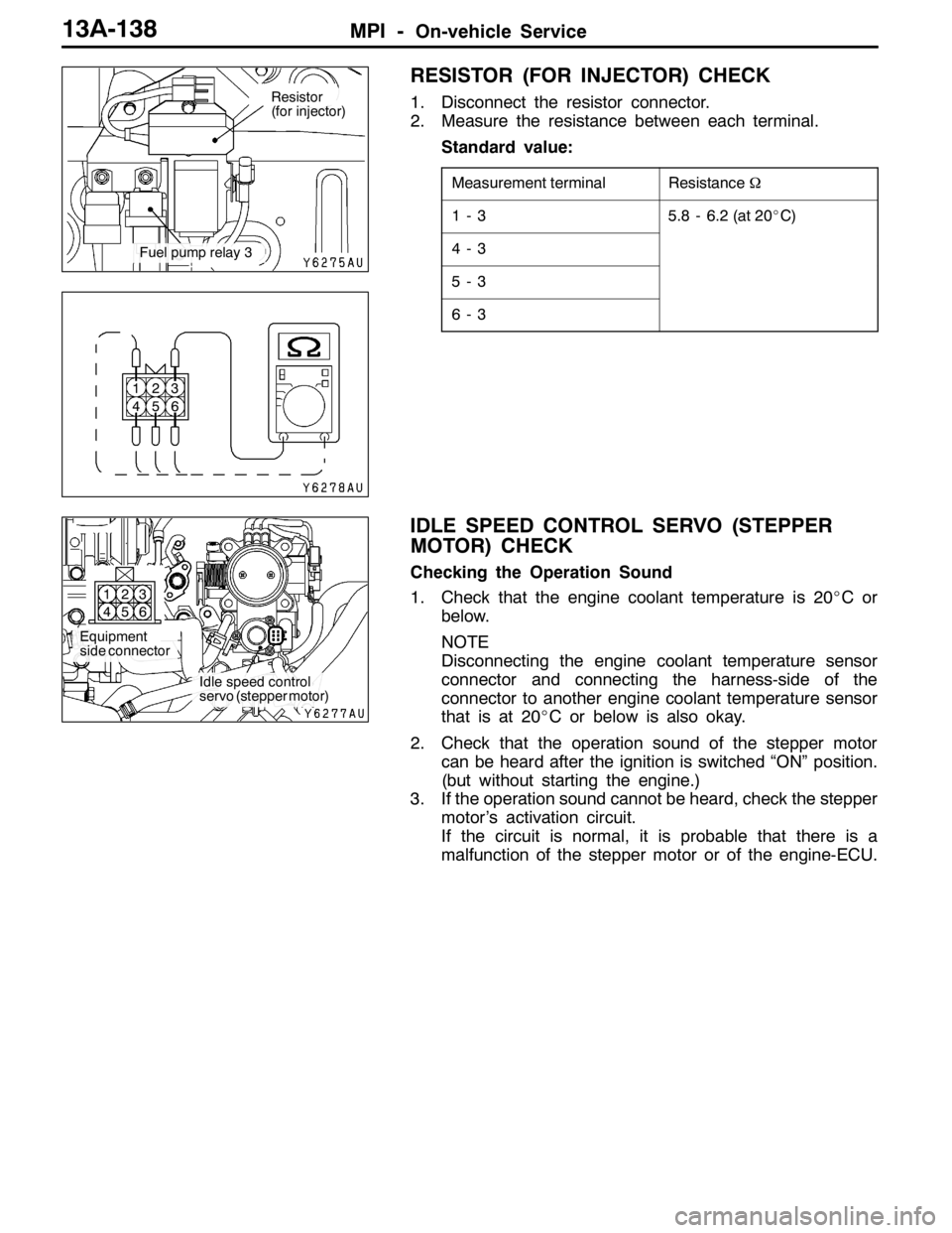
RESISTOR (FOR INJECTOR) CHECK
1. Disconnect the resistor connector.
2. Measure the resistance between each terminal.
Standard value:
Measurement terminalResistanceΩ
1-35.8 - 6.2 (at 20_C)
4-3
5-3
6-3
IDLE SPEED CONTROL SERVO (STEPPER
MOTOR) CHECK
Checking the Operation Sound
1. Check that the engine coolant temperature is 20_Cor
below.
NOTE
Disconnecting the engine coolant temperature sensor
connector and connecting the harness-side of the
connector to another engine coolant temperature sensor
that is at 20_C or below is also okay.
2. Check that the operation sound of the stepper motor
can be heard after the ignition is switched “ON” position.
(but without starting the engine.)
3. If the operation sound cannot be heard, check the stepper
motor’s activation circuit.
If the circuit is normal, it is probable that there is a
malfunction of the stepper motor or of the engine-ECU.
Resistor
(for injector)
Fuel pump relay 3
1
42
53
6
Equipment
side connector
Idle speed control
servo (stepper motor) 1
42
53
6
Page 692 of 1449
ENGINE COOLING -Troubleshooting14-4
Measure at the engine-ECU connector C-126.
DConnect the connector.
DPull out the teminal No.21 to disconnect it
(Ignition switch: ON)
OK:Radiator fan motor is rotated.
YES
Engine-ECU terminal voltage check
(Refer to GROUP 13A - Troubleshooting.)NO
Replace the radiator fan controller.
NG
Repair
OK
NG
Repair
OK
Check the harness wire between radiator fan controller and
engine-ECU.
Measure at the engine-ECU connector C-126.
DConnect the connector.
DVoltage between terminal 21 and body earth
(Engine: Idling, engine coolant temperature: 95_C or more)
OK:0.7 V or more
DConnect the connector.
DVoltage between terminal 21 and body earth
(Engine: Idling, A/C switch: ON)
OK:0.7 V or more (When A/C compressor is operating)NG
(2) NGCheck the harness wire between radiator fan controller and
body earth, and repair if necessary.
OK
Measure at the radiator fan controller connector A-21.
DDisconnect the connector, and measure at the harness
side.
(1) Voltage between terminal 3 and body earth
(Ignition switch: ON)
OK:Battery voltage
(2) Continuity between terminal 1 and body earth
OK:Continuity(1) NGCheck the harness wire between radiator fan controller and
radiator fan relay, and repair if necessary.
(3) NGCheck the harness wire between radiator fan relay and body
earth, and repair if necessary.
(2) NGCheck the harness wire between radiator fan relay and engine
control relay, and repair if necessary.
OK
Measure at the radiator fan control relay connector A-09X.
DRemove the relay, and measure at the relay box side.
(1) Voltage between terminal 4 and body earth
OK:Battery voltage
(2) Voltage between terminal 1 and body earth
(Ignition switch: ON)
OK:Battery voltage
(3) Continuity between terminal 3 and body earth
OK:Continuity(1) NGCheck the harness wire between radiator fan relay and fusible
link (2), and repair if necessary.
DFusible link (2) check
DRadiator fan relay continuity check
(Refer to P.14-8.)
DRadiator fan motor check (Refer to P.14-10.)NG
Replace
OK
OK
Engine-ECU terminal voltage check
(Refer to GROUP 13A - Troubleshooting.)
Check the following connectors:
NG
Check the trouble symptoms.
Page 693 of 1449
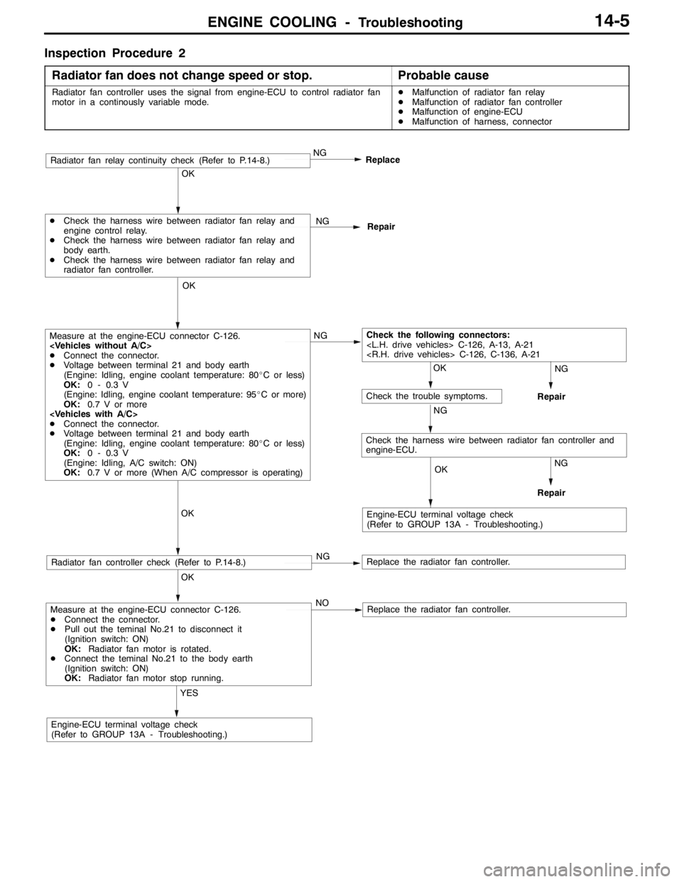
ENGINE COOLING -Troubleshooting14-5
Inspection Procedure 2
Radiator fan does not change speed or stop.
Probable cause
Radiator fan controller uses the signal from engine-ECU to control radiator fan
motor in a continously variable mode.DMalfunction of radiator fan relay
DMalfunction of radiator fan controller
DMalfunction of engine-ECU
DMalfunction of harness, connector
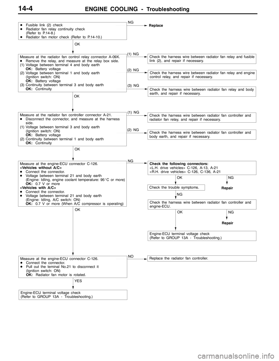
Measure at the engine-ECU connector C-126.
DConnect the connector.
DPull out the teminal No.21 to disconnect it
(Ignition switch: ON)
OK:Radiator fan motor is rotated.
DConnect the teminal No.21 to the body earth
(Ignition switch: ON)
OK:Radiator fan motor stop running.
YES
Engine-ECU terminal voltage check
(Refer to GROUP 13A - Troubleshooting.)NO
Replace the radiator fan controller.
OK
Radiator fan controller check (Refer to P.14-8.)NGReplace the radiator fan controller.
OK
Measure at the engine-ECU connector C-126.
DConnect the connector.
DVoltage between terminal 21 and body earth
(Engine: Idling, engine coolant temperature: 80_C or less)
OK:0 - 0.3 V
(Engine: Idling, engine coolant temperature: 95_C or more)
OK:0.7 V or more
DConnect the connector.
DVoltage between terminal 21 and body earth
(Engine: Idling, engine coolant temperature: 80_C or less)
OK:0 - 0.3 V
(Engine: Idling, A/C switch: ON)
OK:0.7 V or more (When A/C compressor is operating)NG
OK
DCheck the harness wire between radiator fan relay and
engine control relay.
DCheck the harness wire between radiator fan relay and
body earth.
DCheck the harness wire between radiator fan relay and
radiator fan controller.NG
Repair
NG
Replace
OK
OK
OK
Check the following connectors:
NG
Engine-ECU terminal voltage check
(Refer to GROUP 13A - Troubleshooting.)
Check the trouble symptoms.
NG
NG
Repair
Repair
Radiator fan relay continuity check (Refer to P.14-8.)
Check the harness wire between radiator fan controller and
engine-ECU.
Page 710 of 1449
INTAKE AND EXHAUST -On-vehicle Service15-4
4. When the indicated supercharging is more than standard
value, supercharging control may be faulty, therefore
check the followings.
DMalfunction of the waste gate actuator
DMalfunction of waste gate valve
DDisconnection or cracks of the waste gate actuator
rubber hose
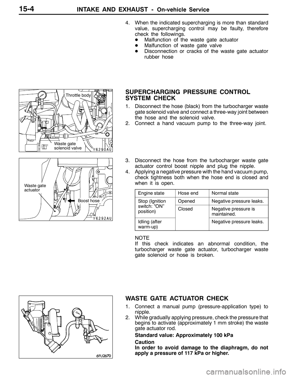
SUPERCHARGING PRESSURE CONTROL
SYSTEM CHECK
1. Disconnect the hose (black) from the turbocharger waste
gate solenoid valve and connect a three-way joint between
the hose and the solenoid valve.
2. Connect a hand vacuum pump to the three-way joint.
3. Disconnect the hose from the turbocharger waste gate
actuator control boost nipple and plug the nipple.
4. Applying a negative pressure with the hand vacuum pump,
check tightness both when the hose end is closed and
when it is open.
Engine stateHose endNormal state
Stop (Ignition
it h“ON”
OpenedNegative pressure leaks.p(g
switch: “ON”
position)ClosedNegative pressure is
maintained.
Idling (after
warm-up)Negative pressure leaks.
NOTE
If this check indicates an abnormal condition, the
turbocharger waste gate actuator, turbocharger waste
gate solenoid or hose is broken.
WASTE GATE ACTUATOR CHECK
1. Connect a manual pump (pressure-application type) to
nipple.
2. While gradually applying pressure, check the pressure that
begins to activate (approximately 1 mm stroke) the waste
gate actuator rod.
Standard value: Approximately 100 kPa
Caution
In order to avoid damage to the diaphragm, do not
apply a pressure of 117 kPa or higher.
Waste gate
solenoid valveThrottle body
Waste gate
actuator
Boost hose