2007 MITSUBISHI LANCER EVOLUTION weight
[x] Cancel search: weightPage 861 of 1449

MANUAL TRANSMISSION - Transmission Assembly22A-53
10
10 11
9
1412 88
13
48±5 N·m
48±5 N·m
48±5 N·m
48±5 N·m
9.0±1.0 N·m
26±5 N·m
82±7 N·m*
47±7 N·m*
8. Transmission assembly upper part
coupling bolts
AA"9. Transmission mount assembly
"AA10. Transmission mount stopper
11. Transmission mount bracket
AB"DEngine assembly supporting
AC"DClutch release bearing connection
12. Bell housing cover13. Transmission assembly lower part
coupling bolts
14. Transmission assembly
Caution
*: Indicates parts which should be initially tightened,
and then fully tightened after placing the vehicle
horizontally and loading the full weight of the engine
on the vehicle body.
REMOVAL SERVICE POINTS
AA"ENGINE AND TRANSMISSION ASSEMBLY
SUPPORTING/TRANSMISSION MOUNT
ASSEMBLY REMOVAL
While supporting the engine and transmission assembly with
a garage jack, remove the transmission mount assembly.Engine and transmission
assembly
Garage jack
Page 935 of 1449
FRONT AXLE -Hub and Knuckle Assembly26-7
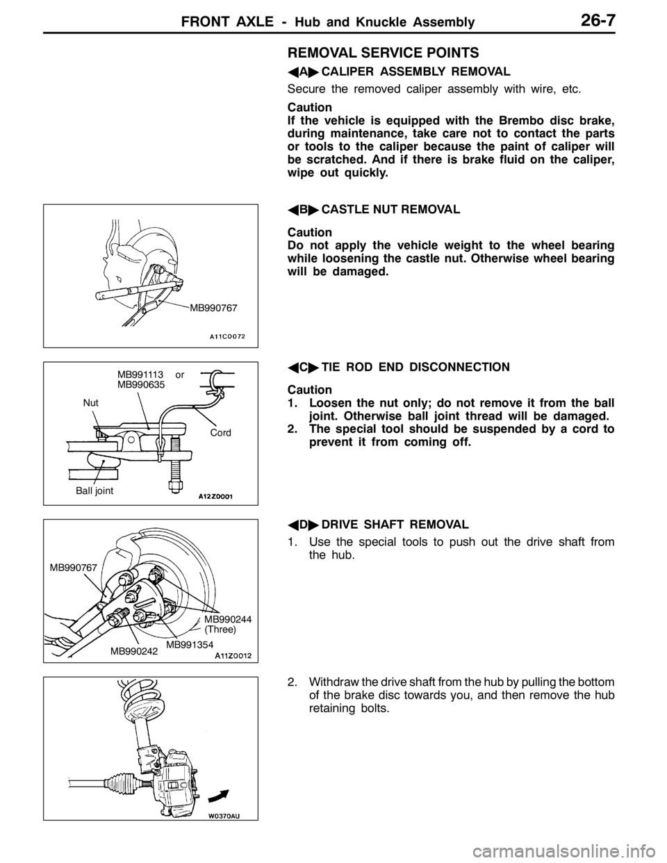
REMOVAL SERVICE POINTS
AA"CALIPER ASSEMBLY REMOVAL
Secure the removed caliper assembly with wire, etc.
Caution
If the vehicle is equipped with the Brembo disc brake,
during maintenance, take care not to contact the parts
or tools to the caliper because the paint of caliper will
be scratched. And if there is brake fluid on the caliper,
wipe out quickly.
AB"CASTLE NUT REMOVAL
Caution
Do not apply the vehicle weight to the wheel bearing
while loosening the castle nut. Otherwise wheel bearing
will be damaged.
AC"TIE ROD END DISCONNECTION
Caution
1. Loosen the nut only; do not remove it from the ball
joint. Otherwise ball joint thread will be damaged.
2. The special tool should be suspended by a cord to
prevent it from coming off.
AD"DRIVE SHAFT REMOVAL
1. Use the special tools to push out the drive shaft from
the hub.
2. Withdraw the drive shaft from the hub by pulling the bottom
of the brake disc towards you, and then remove the hub
retaining bolts.
MB990767
Nut
Cord
Ball joint
MB991113 or
MB990635
MB990242 MB990767MB991354
MB990244
(Three)
Page 939 of 1449
FRONT AXLE -Drive Shaft26-11
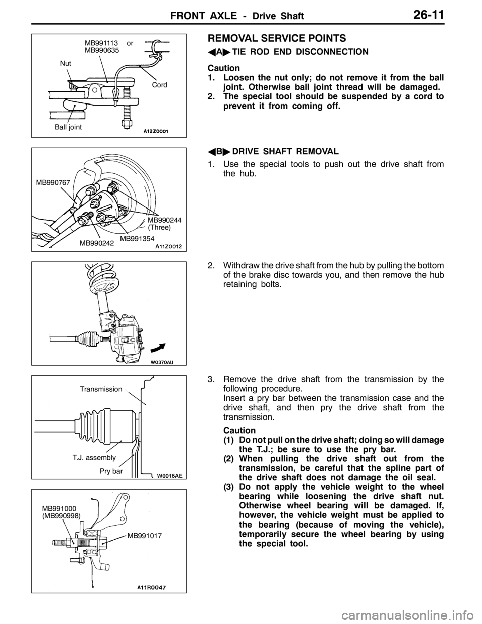
REMOVAL SERVICE POINTS
AA"TIE ROD END DISCONNECTION
Caution
1. Loosen the nut only; do not remove it from the ball
joint. Otherwise ball joint thread will be damaged.
2. The special tool should be suspended by a cord to
prevent it from coming off.
AB"DRIVE SHAFT REMOVAL
1. Use the special tools to push out the drive shaft from
the hub.
2. Withdraw the drive shaft from the hub by pulling the bottom
of the brake disc towards you, and then remove the hub
retaining bolts.
3. Remove the drive shaft from the transmission by the
following procedure.
Insert a pry bar between the transmission case and the
drive shaft, and then pry the drive shaft from the
transmission.
Caution
(1) Do not pull on the drive shaft; doing so will damage
the T.J.; be sure to use the pry bar.
(2) When pulling the drive shaft out from the
transmission, be careful that the spline part of
the drive shaft does not damage the oil seal.
(3) Do not apply the vehicle weight to the wheel
bearing while loosening the drive shaft nut.
Otherwise wheel bearing will be damaged. If,
however, the vehicle weight must be applied to
the bearing (because of moving the vehicle),
temporarily secure the wheel bearing by using
the special tool.
Nut
Cord
Ball joint
MB991113 or
MB990635
MB990242 MB990767MB991354
MB990244
(Three)
T.J. assembly
Pry bar
Transmission
MB991000
(MB990998)
MB991017
Page 972 of 1449
REAR AXLE -Rear Hub Assembly27B-26
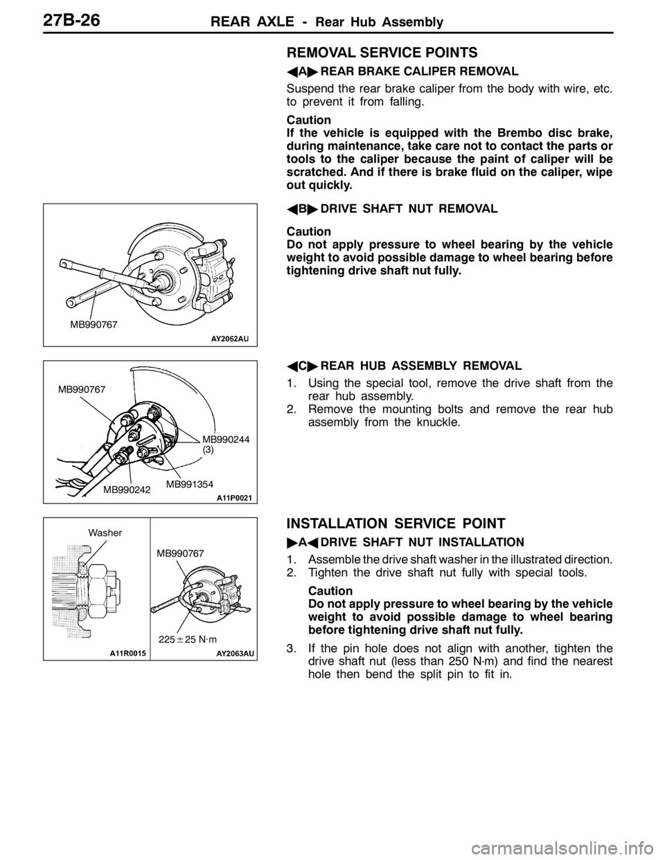
REMOVAL SERVICE POINTS
AA"REAR BRAKE CALIPER REMOVAL
Suspend the rear brake caliper from the body with wire, etc.
to prevent it from falling.
Caution
If the vehicle is equipped with the Brembo disc brake,
during maintenance, take care not to contact the parts or
tools to the caliper because the paint of caliper will be
scratched. And if there is brake fluid on the caliper, wipe
out quickly.
AB"DRIVE SHAFT NUT REMOVAL
Caution
Do not apply pressure to wheel bearing by the vehicle
weight to avoid possible damage to wheel bearing before
tightening drive shaft nut fully.
AC"REAR HUB ASSEMBLY REMOVAL
1. Using the special tool, remove the drive shaft from the
rear hub assembly.
2. Remove the mounting bolts and remove the rear hub
assembly from the knuckle.
INSTALLATION SERVICE POINT
"AADRIVE SHAFT NUT INSTALLATION
1. Assemble the drive shaft washer in the illustrated direction.
2. Tighten the drive shaft nut fully with special tools.
Caution
Do not apply pressure to wheel bearing by the vehicle
weight to avoid possible damage to wheel bearing
before tightening drive shaft nut fully.
3. If the pin hole does not align with another, tighten the
drive shaft nut (less than 250 N
·m) and find the nearest
hole then bend the split pin to fit in.
MB990767
MB990767
MB990242MB991354
MB990244
(3)
MB990767
225±25 N·m
Washer
Page 976 of 1449
REAR AXLE -Drive Shaft27B-30
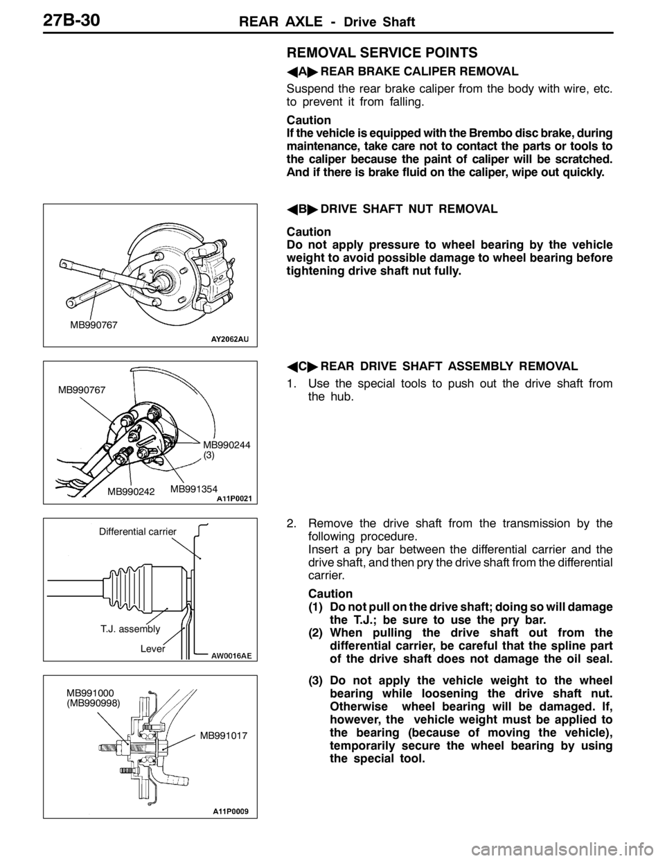
REMOVAL SERVICE POINTS
AA"REAR BRAKE CALIPER REMOVAL
Suspend the rear brake caliper from the body with wire, etc.
to prevent it from falling.
Caution
If the vehicle is equipped with the Brembo disc brake, during
maintenance, take care not to contact the parts or tools to
the caliper because the paint of caliper will be scratched.
And if there is brake fluid on the caliper, wipe out quickly.
AB"DRIVE SHAFT NUT REMOVAL
Caution
Do not apply pressure to wheel bearing by the vehicle
weight to avoid possible damage to wheel bearing before
tightening drive shaft nut fully.
AC"REAR DRIVE SHAFT ASSEMBLY REMOVAL
1. Use the special tools to push out the drive shaft from
the hub.
2. Remove the drive shaft from the transmission by the
following procedure.
Insert a pry bar between the differential carrier and the
drive shaft, and then pry the drive shaft from the differential
carrier.
Caution
(1) Do not pull on the drive shaft; doing so will damage
the T.J.; be sure to use the pry bar.
(2) When pulling the drive shaft out from the
differential carrier, be careful that the spline part
of the drive shaft does not damage the oil seal.
(3) Do not apply the vehicle weight to the wheel
bearing while loosening the drive shaft nut.
Otherwise wheel bearing will be damaged. If,
however, the vehicle weight must be applied to
the bearing (because of moving the vehicle),
temporarily secure the wheel bearing by using
the special tool.
MB990767
MB990767
MB990242MB991354
MB990244
(3)
Differential carrier
T.J. assembly
Lever
MB991017 MB991000
(MB990998)
Page 977 of 1449
REAR AXLE -Drive Shaft27B-31
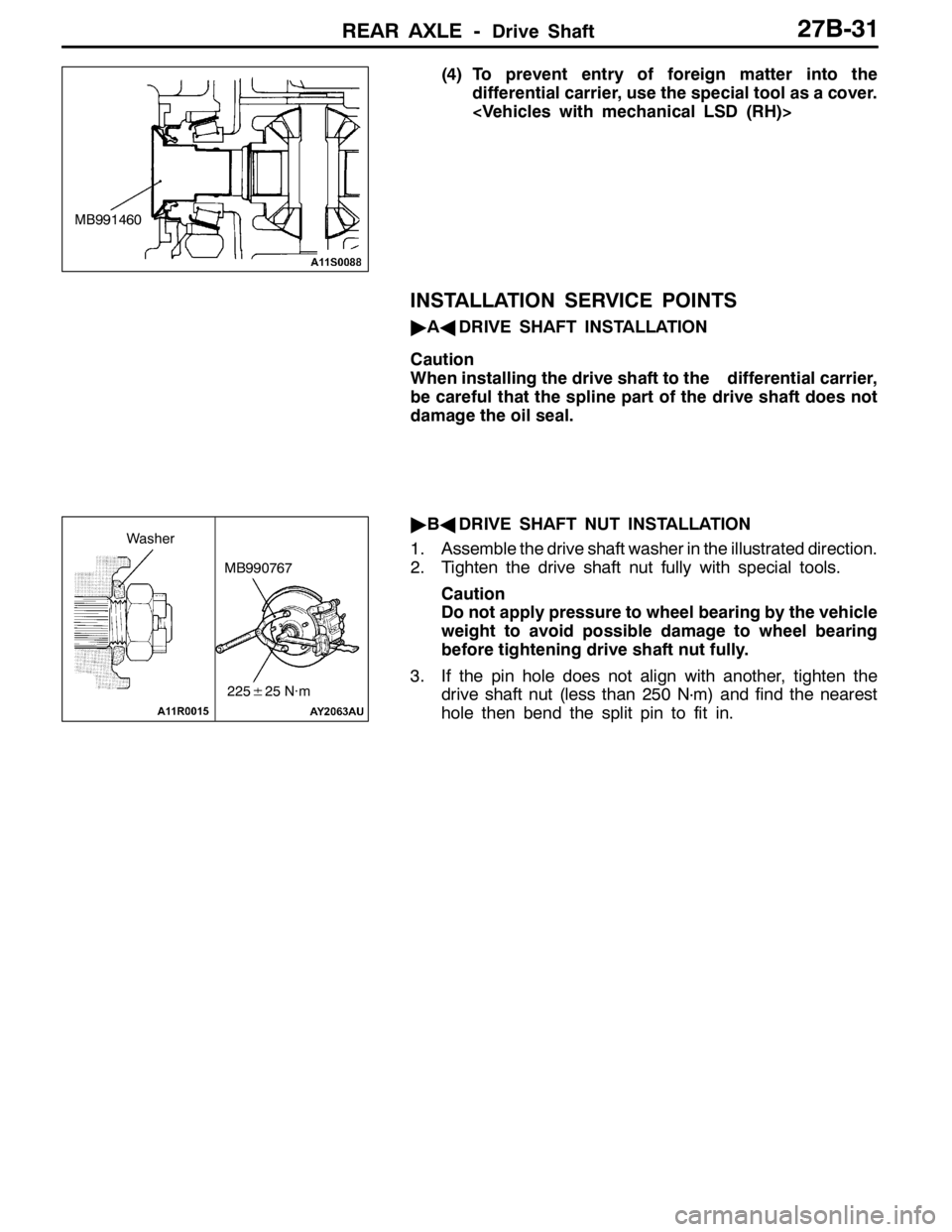
(4) To prevent entry of foreign matter into the
differential carrier, use the special tool as a cover.
INSTALLATION SERVICE POINTS
"AADRIVE SHAFT INSTALLATION
Caution
When installing the drive shaft to the differential carrier,
be careful that the spline part of the drive shaft does not
damage the oil seal.
"BADRIVE SHAFT NUT INSTALLATION
1. Assemble the drive shaft washer in the illustrated direction.
2. Tighten the drive shaft nut fully with special tools.
Caution
Do not apply pressure to wheel bearing by the vehicle
weight to avoid possible damage to wheel bearing
before tightening drive shaft nut fully.
3. If the pin hole does not align with another, tighten the
drive shaft nut (less than 250 N
·m) and find the nearest
hole then bend the split pin to fit in.
MB991460
MB990767
225±25 N·m
Washer
Page 1012 of 1449

WHEEL AND TYRE -Troubleshooting31-4
WHEEL BALANCE ACCURACY
PURPOSE
This section contains tips and procedures for
achieving accurate wheel balance. Steering wheel
vibration and /or body shake can result if any of
these procedures are not carefully observed.
1. Wheels and tires must be properly mounted
on a balancer in order to achieve correct
balance. Centering the wheel on the shaft of
the balancer is essential for proper mounting.
2. Off-the-car wheel balancers must be calibrated
periodically to ensure good balancing results.
An inaccurately calibrated balancer could cause
unnecessary replacement of tires, shocks,
suspension components, or steering
components.Check your balancer’s calibration approximately
every 100 balances. Your wheel balancer’s
instruction manual should include calibration
procedures. If the calibration procedures
specifically for your balancer are missing, use the
generic steps in this section for zero calibration,
static balance, and dynamic balance checks. The
wheel balancer calibration checks are also
described in the flowchart. (Refer to P.31-5.)
PROCEDURE
Balancing Tips
1. Confirm that the balancer’s cone and the wheel
mounting cone are undamaged and free of
dirt and rust.
2. On this vehicle the wheel’s center hole on the
hub side has a chamfered edge. Use a
back-mounting cone on your wheel balancer
to center the wheel on the balancer shaft.3. Install a wheel mounting cone. The appropriate
size cone for this vehicle is 67.0 mm.
4. Before balancing the wheel, remove any wheel
weights from both sides. Also check both sides
for any damage.
5. When installing wheel weights, hammer them
at a straight (not diagonal) angle.
Hub/shaft assembly
Spring plateClamping cup
Wheel mounting
cone
Standard passenger
car wheelWing nut
Confirming Proper Balance
1. After balancing the wheel, loosen the wing nut
and turn the wheel 180°against the balancer’s
hub. Then retighten the wing nut and check
the balance again. Repeat wheel balance if
necessary.2. Turn the wheel again 180°against the
balancer’s hub. If the wheel becomes
out-of-balance each time it is turned against
the balancer’s hub, the wheel balancer may
require calibration.
Wheel Balancer Calibration Checks
1. Mount an undamaged original-equipment alloy
rim and tire assembly (wheel) onto your
off-the-car wheel balancer. Balance the wheel.2.<
Loosen the balancer wing nut, rotate the wheel
a half turn (180°), and retighten the nut.
Recheck the balance.
Page 1013 of 1449
WHEEL AND TYRE -Troubleshooting31-5
DIf the imbalance is 5 g or less, the zero
calibration is OK. Rebalance the wheel, then
go to Step 4 to check static balance.
DIf the imbalance is more than 5 g, go to Step
3.
3. Loosen the balancer wing nut, rotate the wheel
1/4 turn (90°), and retighten the nut. Recheck
the wheel balance.
DIf the imbalance is 5 g or less, the wheel may
not be centered on the balancer, or the
balancing cones, the cup, and/or wing nut are
damaged, dirty, or inappropriate for the wheel.
You may need to refer to the balancer
manufacturer’s instructions to verify the correct
attachments. after making the necessary
corrections, recheck the wheel balance. If OK,
then go to Step 4.
DIf the imbalance is more than 5 g, the balancer
requires calibration. Contact the balancer
manufacturer for calibration by their repair
representative.
4.<
Attach a 5-g weight to the outer rim. Recheck
the balancer. The balancer should detect 5±2
g of imbalance 170°to 190°away from both the
inner and outer 5-g weights.DIf the imbalance is within specification, the static
balance calibration is correct. Go to Step 5
to check the dynamic balance.
DIf the imbalance is out of specification, the
balancer requires calibration. Contact the
balancer manufacturer for calibration by their
repair representative.
5.<
Attach a 5-g weight to the inner rim at 180°
opposite the 5-g weight that was added in step
4. Recheck the balance. The balancer should
detect 5±2g of imbalance 170°to 190°away
from both the inner and outer 5-g weights.
DIf the imbalance is within specification, the
dynamic balance calibration is correct. The
balancer calibration checks are complete.
DIf the imbalance is out of specification, the
balancer requires calibration. Contact the
balancer manufacturer for calibration by their
repair representative.
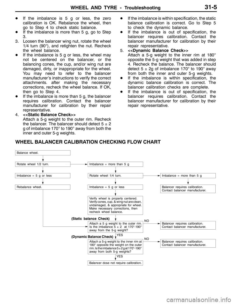
WHEEL BALANCER CALIBRATION CHECKING FLOW CHART
(Dynamic Balance Check)
(Static balance Check)
Balance wheel.
Rotate wheel 1/2 turn.Imbalance = more than 5 g
Imbalance = 5 g or lessRotate wheel 1/4 turn.Imbalance = more than 5 g
Imbalance = 5 g or less
Verify wheel is properly centered.
Verify cones, cup, & wing nut are clean,
undamaged, & appropriate for wheel.
Make necessary corrections, then
recheck wheel balance.
Attach a 5 g weight to the outer rim.
Is the imbalance 5±2 at 170°-190°
away from the 5-g weight?NOBalancer requires calibration.
Contact balancer manufacturer.
Balancer requires calibration.
Contact balancer manufacturer.
YES
Attach a 5-g weight to the inner rim at
180°opposite the weight on the outer
rim. Is the imbalance 5±2gat170°-190°
away from both 5-g weights?NOBalancer requires calibration.
Contact balancer manufacturer.
Rebalance wheel.
YES
Balancer dose not require calibration.