Page 1018 of 1449
POWER PLANT MOUNT - Engine Mounting32-4
ENGINE MOUNTING
REMOVAL AND INSTALLATION
Caution
*: Indicates parts which should be initially tightened, and then fully tightened after placing the
vehicle horizontally and loading the full weight of the engine on the vehicle body.
Pre-removal and Post-installation Operation
DUnder Cover Removal and Installation (Refer to
GROUP 51 - Front Bumper.)DRaise the engine and transmission assembly until
its weight is not applied to the insulator, and support
it securely.
98±10 N·m*
67±7 N·m*
1
2
12±2 N·m
3 44
Removal steps
1. Power steering pressure hose as-
sembly
2. Engine mounting connecting bolt3. Engine mounting bracket
"AA4. Engine mounting insulator
INSTALLATION SERVICE POINT
"AAENGINE MOUNTING INSULATOR INSTALLATION
Arrow marks on the engine mount insulator should face the
shown direction.
NOTE
Disregard F and R stamped as a shared part.
Engine sideEngine side
Engine mounting insulator
>
Page 1019 of 1449

POWER PLANT MOUNT - Transmission Mounting32-5
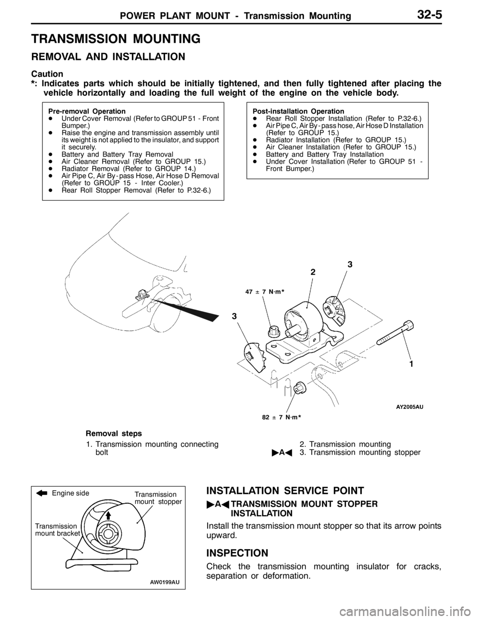
TRANSMISSION MOUNTING
REMOVAL AND INSTALLATION
Caution
*: Indicates parts which should be initially tightened, and then fully tightened after placing the
vehicle horizontally and loading the full weight of the engine on the vehicle body.
Pre-removal Operation
DUnder Cover Removal (Refer to GROUP 51 - Front
Bumper.)
DRaise the engine and transmission assembly until
its weight is not applied to the insulator, and support
it securely.
DBattery and Battery Tray Removal
DAir Cleaner Removal (Refer to GROUP 15.)
DRadiator Removal (Refer to GROUP 14.)
DAir Pipe C, Air By - pass Hose, Air Hose D Removal
(Refer to GROUP 15 - Inter Cooler.)
DRear Roll Stopper Removal (Refer to P.32-6.)Post-installation Operation
DRear Roll Stopper Installation (Refer to P.32-6.)
DAir Pipe C, Air By - pass hose, Air Hose D Installation
(Refer to GROUP 15.)
DRadiator Installation (Refer to GROUP 15.)
DAir Cleaner Installation (Refer to GROUP 15.)
DBattery and Battery Tray Installation
DUnder Cover Installation (Refer to GROUP 51 -
Front Bumper.)
47±7 N·m*
3
3
82±7 N·m*
2
1
Removal steps
1. Transmission mounting connecting
bolt2. Transmission mounting
"AA3. Transmission mounting stopper
INSTALLATION SERVICE POINT
"AATRANSMISSION MOUNT STOPPER
INSTALLATION
Install the transmission mount stopper so that its arrow points
upward.
INSPECTION
Check the transmission mounting insulator for cracks,
separation or deformation.
Engine side
Transmission
mount bracketTransmission
mount stopper
Page 1020 of 1449
POWER PLANT MOUNT - Engine Roll Stopper, Centermember32-6
ENGINE ROLL STOPPER, CENTERMEMBER
REMOVAL AND INSTALLATION
Caution
*: Indicates parts which should be initially tightened, and then fully tightened after placing the
vehicle horizontally and loading the full weight of the engine on the vehicle body.
Pre-removal and Post-installation Operation
Under Cover Removal and Installation (Refer to GROUP 51 - Front Bumper.)
52±7 N·m*
69±10 N·m
52±7 N·m*
52±7 N·m*
70±10 N·m
1 2
3 45 6
1 78
70±10 N·m
49±10 N·m
69±10 N·m
49±10 N·m
9
35±5 N·m*
10
35±5 N·m*
Front roll stopper and centermember
removal steps
1. Crossmember bar
2. Front roll stopper connecting bolt
3. Centermember
"AA4. Front roll stopper
5. Front roll mount bracketRear roll rod removal steps
6. Rear roll rod connecting bolt
7. Rear roll mount bracket
8. Rear roll rod connecting bolt
9. Rear roll rod bracket
10. Rear roll rod assembly
Page 1022 of 1449

POWER PLANT MOUNT - Crossmember32-8
CROSSMEMBER
REMOVAL AND INSTALLATION
Caution
1. Before removing the steering wheel and air bag module assembly, always refer to GROUP
52B - Service Precautions, Air bag Module and Clock Spring. Also, set the front wheels so
that they are facing straight forward, and remove the ignition key. If you fail to do this, the
SRS clock spring will be damaged, causing the SRS air bag to be inoperative and serious
injury.
2. *
1: Indicates parts which should be initially tightened, and then fully tightened after placing
the vehicle horizontally and loading the full weight of the engine on the vehicle body.
3. *
2: Indicates parts which should be temporarily tightened, and then fully tightened with the
vehicle on the ground in the unladen condition.
Caution
If the vehicle is equipped the Brembo disc brake, during maintenance, take care not to contact
the parts or tools to the caliper because the paint of caliper will be scratched.
Pre-removal Operations
DUnder Cover Removal
(Refer to GROUP 51 - Front Bumper.)
DCentermember, Crossmember Bar Removal
(Refer to P.32-6.)
DFront Exhaust Pipe Removal
(Refer to GROUP 15.)
DSteering Wheel Air Bag Module Assembly Removal
(Refer to GROUP 37A.)
DPower Steering Fluid Draining
(Refer to GROUP 37A - On-vehicle Service.)Post-installation Operations
DCentermember, Crossmember Bar Installation
(Refer to P.32-6.)
DFront Exhaust Pipe Installation
(Refer to GROUP 15.)
DSteering Wheel Air Bag Module Assembly
Installation (Refer to GROUP 37A.)
DPower Steering Fluid Supplying
(Refer to GROUP 37A - On-vehicle Service.)
DPower Steering Fluid Line Bleeding
(Refer to GROUP 37A - On-vehicle Service.)
DPress the dust cover with a finger to check whether
the dust cover is cracked or damaged.
DChecking Steering Wheel Position with Wheels
Straight Ahead
DFront Wheel Alignment Check and Adjustment
(Refer to GROUP 37A - On-vehicle Service.)
DUnder Cover Installation
(Refer to GROUP 51 - Front Bumper.)
Page 1116 of 1449

STEERING -General Information37A-2
GENERAL INFORMATION
The system has been equipped with the MOMO
leather 3-spoke-type steering wheel with built-in
SRS airbag.
The steering column is equipped with tilt steering
mechanism.
The power steering is an integral rack and piniontype that combines the steering gear and linkage
into one light-weight and compact assembly.
The steering system uses a vane oil pump with
a fluid flow control system, so that steering effort
varies with engine speed.
ItemLancer EVOLUTION-
Steering wheelTypeMOMO 3-spoke typeg
Outside diameter mm380 ,
365
Maximum number of turns2.1
Steering columnColumn mechanismTilt steering
Power steering typeIntegral type
Oil pumpTypeVariable capacity type (vane pump)pp
Basic discharge amount cm3/rev.9.6
Relief pressure MPa8.3 - 9.0
Reservoir typeSeparate type
Pressure switchEquipped
Steering gear and linkageTypeRack and pinionggg
Stroke ratio (Rack stroke/Steering wheel
Maximum turning radius)68.61
Rack stroke mm146
Steering angleInner wheel32°gg
Outer wheel (for reference)27°
Power steering fluidSpecified lubricantsAutomatic transmission fluid DEXRON IIg
Quantity LApproximately 1.0
Page 1144 of 1449
STEERING - Power Steering Oil Pump/Power Steering Oil Hoses37A-30
"BAPRESSURE HOSE ASSEMBLY/SUCTION HOSE
REMOVAL
Install the pressure hose assembly and suction hose as
illustrated.
DISASSEMBLY AND REASSEMBLY
21±3 N·m
3
4
2 1
39±5 N·m
: Automatic transmission fluid DEXRONII
NOTE
Disassembly steps
1. Suction connector
2. O-ring3. Connector
4. Gasket
POWER STEERING OIL HOSES
REMOVAL AND INSTALLATION
Caution
1. Before removing the clock spring, always see GROUP 52B - Caution for Service and Air Bag
Module Clock Spring
2. If the vehicle is equipped with the Brembo disc brake, during maintenance, take care not to
contact the parts or tools to the caliper, because the paint of caliper will be scratched.
3. On the tightening section indicated in the mark (*), lightly tighten the nut first, and then finally
tighten it with the engine weight applied on the body.
Suction hose
Pressure hose
assembly
Marking
Notch
Page 1345 of 1449

CHASSIS ELECTRICAL -Headlamp Assembly54A-25
4. If the fuel tank is not full, place a weight in luggage room
of vehicle to simulate weight of a full tank 0.8 kg per litre.
5. There should be no other load in the vehicle other than
driver or substituted weight of approximately 75 kg placed
in driver’s position.
6. Thoroughly clean headlamp lenses.
7. Place the vehicle on a level floor, perpendicular to a flat
screen 10m away from the bulb center - marks on the
headlamp lens.
8. Rock vehicle sideways to allow vehicle to assume its
normal position.
9. Bounce the front suspension through three (3) oscillations
by applying the body weight to hood or bumper.
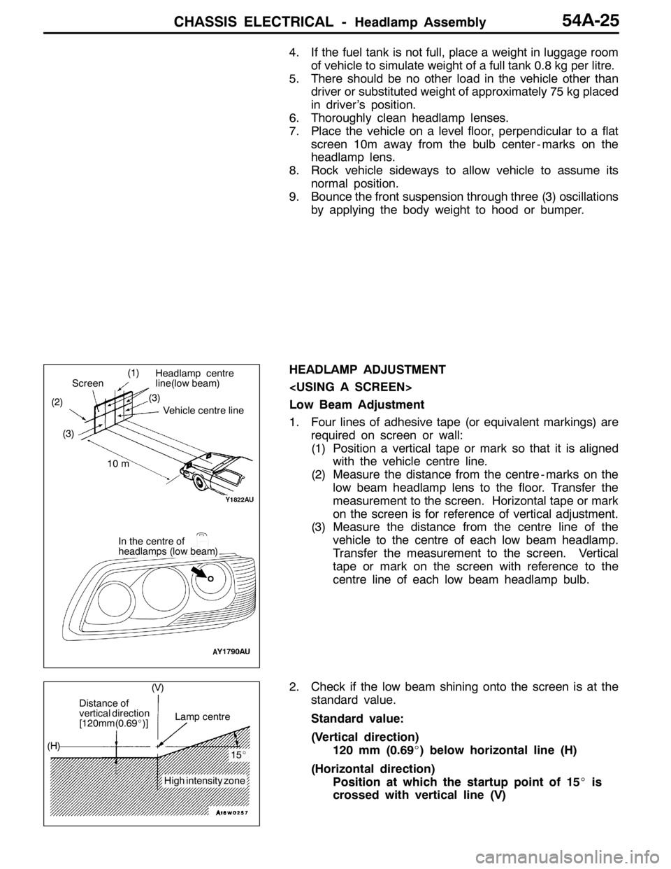
HEADLAMP ADJUSTMENT
Low Beam Adjustment
1. Four lines of adhesive tape (or equivalent markings) are
required on screen or wall:
(1) Position a vertical tape or mark so that it is aligned
with the vehicle centre line.
(2) Measure the distance from the centre - marks on the
low beam headlamp lens to the floor. Transfer the
measurement to the screen. Horizontal tape or mark
on the screen is for reference of vertical adjustment.
(3) Measure the distance from the centre line of the
vehicle to the centre of each low beam headlamp.
Transfer the measurement to the screen. Vertical
tape or mark on the screen with reference to the
centre line of each low beam headlamp bulb.
2. Check if the low beam shining onto the screen is at the
standard value.
Standard value:
(Vertical direction)
120 mm (0.69_) below horizontal line (H)
(Horizontal direction)
Position at which the startup point of 15_is
crossed with vertical line (V)
(1)
(2)(3)
Headlamp centre
line(low beam)
Vehicle centre line
Screen
10 m
In the centre of
headlamps (low beam) (3)
Distance of
vertical direction
[120mm(0.69_)]Lamp centre
15_
High intensity zone (H)(V)
Page:
< prev 1-8 9-16 17-24