Page 696 of 1449
ENGINE COOLING -On-vehicle Service14-8
RADIATOR FAN RELAY CONTINUITY CHECK
Battery voltageTerminal No.
1234
When current is not
supplied
When current is
supplied
RADIATOR FAN CONTROLLER CHECK
1. Remove the center under cover.
(Refer to GROUP 51 - Front Bumper.)
2. Insert the special tool at the back of the radiator fan
motor connector.
3. Connect the special tool to the circuit tester.
4. Disconnect the engine coolant temperature sensor
connector.
Air cleaner
Radiator fan
controller
MB991222
Circuit tester
Connector
rear view
Water outlet
fitting
Engine coolant
temperature
sensor
Page 737 of 1449

ENGINE ELECTRICAL -Charging System16-5
(6) Reconnect the negative battery cable.
(7) Connect a tachometer or the MUT-II.
(Refer to GROUP 11 - On-vehicle Service.)
(8) Leave the hood open.
(9) Start the engine.
(10)With the engine running at 2,500 r/min, turn
the headlamps and other lamps on and off
to adjust the alternator load so that the value
displayed on the ammeter is slightly above 30
A.
Adjust the engine speed by gradually
decreasing it until the value displayed on the
ammeter is 30 A. Take a reading of the value
displayed on the voltmeter at this time.
Limit: max. 0.3 V
NOTE
When the alternator output is high and the value
displayed on the ammeter does not decrease
until 30 A, set the value to 40 A. Read the
value displayed on the voltmeter at this time.
When the value range is 40 A, the limit is max.
0.4 V.(11) If the value displayed on the voltmeter is above
the limit value, there is probably a malfunction
in the alternator output wire, so check the wiring
between the alternator “B” terminal and the
battery (+) terminal (including fusible link).
If a terminal is not sufficiently tight or if the
harness has become discolored due to
overheating, repair and then test again.
(12)After the test, run the engine at idle.
(13)Turn off all lamps and the ignition switch.
(14)Remove the tachometer or the MUT-II.
(15)Disconnect the negative battery cable.
(16)Disconnect the ammeter and voltmeter.
(17)Connect the alternator output wire to the
alternator “B” terminal.
(18)Connect the negative battery cable.
OUTPUT CURRENT TEST
Charging warning lampVoltmeter
Ammeter
Ignition switch
Alternator relayLoad
Battery
Engine-ECUAlternatorFR
L
S
G
+ -+-
B
Page 780 of 1449

ENGINE AND EMISSION CONTROL -Emission Control System
Vacuum tank
Alternator
Purge control solenoid valve
17-10
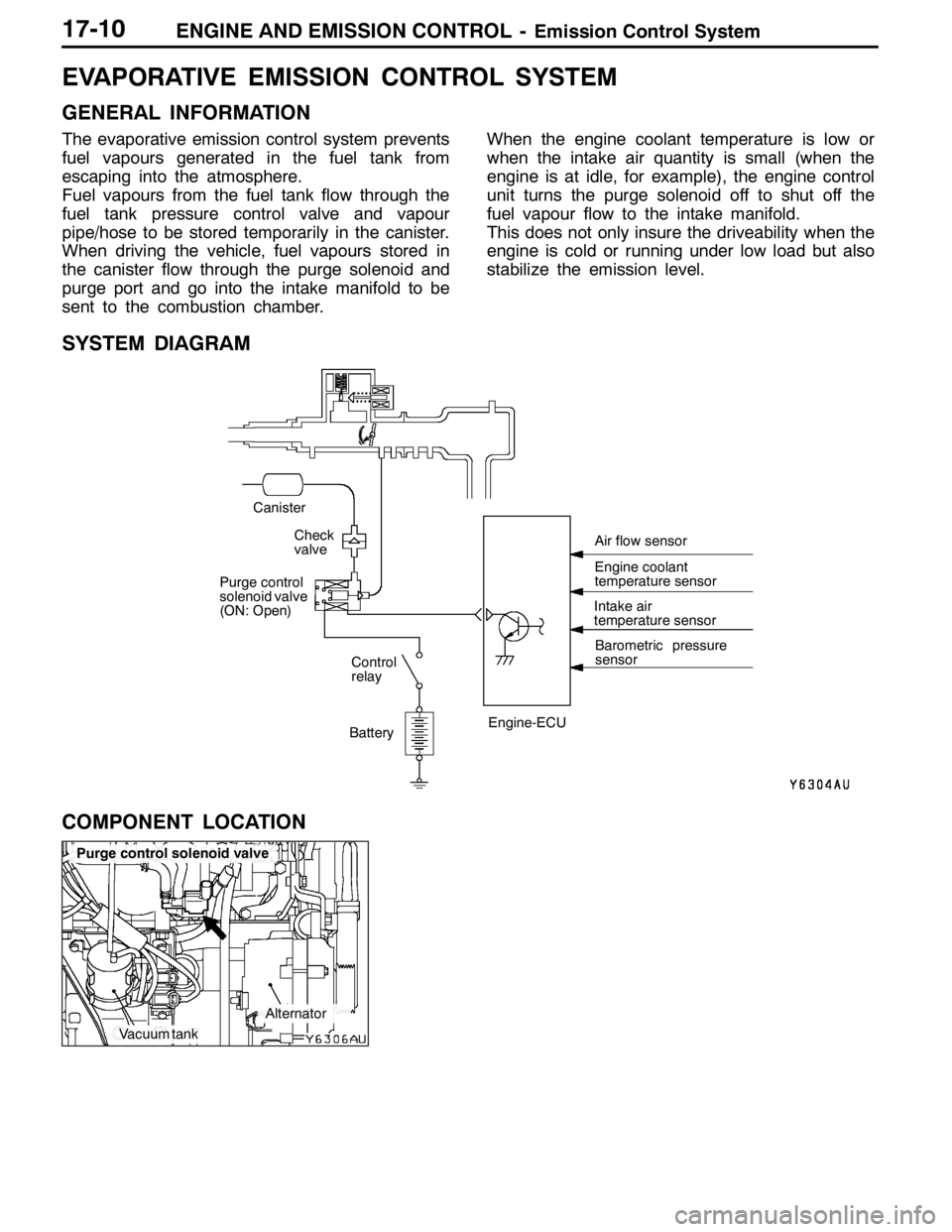
EVAPORATIVE EMISSION CONTROL SYSTEM
GENERAL INFORMATION
The evaporative emission control system prevents
fuel vapours generated in the fuel tank from
escaping into the atmosphere.
Fuel vapours from the fuel tank flow through the
fuel tank pressure control valve and vapour
pipe/hose to be stored temporarily in the canister.
When driving the vehicle, fuel vapours stored in
the canister flow through the purge solenoid and
purge port and go into the intake manifold to be
sent to the combustion chamber.When the engine coolant temperature is low or
when the intake air quantity is small (when the
engine is at idle, for example), the engine control
unit turns the purge solenoid off to shut off the
fuel vapour flow to the intake manifold.
This does not only insure the driveability when the
engine is cold or running under low load but also
stabilize the emission level.
SYSTEM DIAGRAM
BatteryIntake air
temperature sensor
Barometric pressure
sensor
Check
valve
Canister
Control
relay
Purge control
solenoid valve
(ON: Open)
Engine-ECUEngine coolant
temperature sensor Air flow sensor
COMPONENT LOCATION
Page 783 of 1449

ENGINE AND EMISSION CONTROL -Emission Control System17-13
EXHAUST GAS RECIRCULATION (EGR) SYSTEM
GENERAL INFORMATION
The exhaust gas recirculation (EGR) system lowers
the nitrogen oxide (NOx) emission level. When the
air/fuel mixture combustion temperature is high,
a large quantity of nitrogen oxides (NOx) is
generated in the combustion chamber. Therefore,
this system recirculates part of emission gas fromthe exhaust port of the cylinder head to the
combustion chamber through the intake manifold
to decrease the air/fuel mixture combustion
temperature, resulting in reduction of NOx.
The EGR flow rate is controlled by the EGR valve
so as not to decrease the driveability.
OPERATION
The EGR valve is being closed and does not
recirculate exhaust gases under one of the following
conditions. Otherwise, the EGR valve is opened
and recirculates exhaust gases.DThe engine coolant temperature is low.
DThe engine is at idle.
DThe throttle valve is widely opened.
SYSTEM DIAGRAM
ON Throttle body
EGR control
solenoid valve
Engine
control
relay
Battery EGR valve
Crank angle sensor
Throttle position sensor Engine-ECU
Engine coolant
temperature sensor Air flow sensor
Page 810 of 1449

22A-2
MANUAL
TRANSMISSION
CONTENTS
GENERAL 3.................................
Outline of Changes 3...........................
GENERAL INFORMATION 3..................
SERVICE SPECIFICATION 3..................
LUBRICANTS 3..............................
SPECIAL TOOLS 4...........................
TROUBLESHOOTING 5...............
ON-VEHICLE SERVICE 40....................
Transmission Oil Check 40......................
Transmission Oil Replacement 40................
Transfer Oil Check 40..........................
Transfer Oil Replacement 40....................
Fluid Check
ACD and AYC> 41.............................
Bleeding
ACD and AYC> 42.............................ACD Operation Check
vehicles with ACD and AYC> 42................
Hydraulic Pressure Check
vehicles with ACD and AYC> 43................
Wheel Speed Sensor Output Voltage
Measurement
ACD and AYC> 44.............................
TRANSMISSION CONTROL* 46...............
TRANSFER ASSEMBLY 49...................
TRANSMISSION ASSEMBLY 52...............
4WD-ECU
VEHICLES WITH ACD AND AYC> 55.........
SENSOR, SWITCH AND RELAY
WITH ACD OR VEHICLES WITH ACD AND
AYC> 56.....................................
HYDRAULIC UNIT Refer to GROUP27B.......
WARNING REGARDING SERVICING OF SUPPLEMENTAL RESTRAINT SYSTEM (SRS) EQUIPPED VEHICLES
WARNING!
(1) Improper service or maintenance of any component of the SRS, or any SRS-related component, can lead to personal
injury or death to service personnel (from inadvertent firing of the air bag) or to driver and passenger (from rendering
the SRS inoperative).
(2) Service or maintenance of any SRS component or SRS-related component must be performed only at an authorized
MITSUBISHI dealer.
(3) MITSUBISHI dealer personnel must thoroughly review this manual, and especially its GROUP 52B - Supplemental
Restraint System (SRS) before beginning any service or maintenance of any component of the SRS or any SRS-related
component.
NOTE
The SRS includes the following components: SRS-ECU, SRS warning lamp, air bag module, clock spring, and interconnecting
wiring. Other SRS-related components (that may have to be removed/installed in connection with SRS service or maintenance) are
indicated in the table of contents by an asterisk (*).
Page 814 of 1449

MANUAL TRANSMISSION - Troubleshooting 22A-6
INSPECTION CHART FOR DIAGNOSIS CODES
Diagnosis
code No.Diagnosis itemsReference page
12Power supply voltage (valve power supply) systemopen circuit or short-circuit22A-8
13Fail-safe relay system open circuit or short-circuit22A-8
21Wheel speed sensor systemopen circuit or short-circuit22A-9
22Wheel speed sensor systemopen circuit or short-circuit22A-9
23Wheel speed sensor systemopen circuit or short-circuit22A-9
24Wheel speed sensor systemopen circuit or short-circuit22A-9
25Wrong-diameter tire22A-11
26Wheel speed sensor (faulty output signal)22A-13
31Steering wheel sensor systemopen circuit or short-circuit22A-15
32Steering wheel sensor systemshort-circuit22A-16
33fixed22A-16
34Steering wheel sensor systemshort-circuit or output
fixed22A-17
41TPS systemopen circuit or ground22A-18
42short-circuit22A-18
45Pressure sensor systemopen circuit or ground22A-19
46open earth22A-19
47abnormal power supply22A-20
51Longitudinal G sensor systemopen circuit or short-circuit22A-21
52defective sensor22A-22
56Lateral G sensor systemopen circuit or short-circuit22A-23
57defective sensor22A-24
61Stop lamp switch systemopen circuit22A-25
62ACD mode switch systemstuck22A-26
63Parking brake switch systemshort-circuit or not re-
turned to original position22A-27
65ABS monitor systemopen circuit or defective
ABS22A-28
71Proportional valve systemopen circuit or short-circuitRefer to
GROUP27B
72Directional control valve systemopen circuit or short-circuit
GROUP27B.
73Directional control valve systemopen circuit or short-circuit
74Proportional valve systemopen circuit or short-circuit22A-29
Page 815 of 1449
MANUAL TRANSMISSION - Troubleshooting 22A-7
Diagnosis
code No.Reference page Diagnosis items
81Electric pump relay systemopen circuit or short-circuit22A-29
82electric pump malfunction
or pressure sensor defect22A-30
84AYC control errorRefer to
GROUP 27B.
85ACD control error-
NOTE
Code No.85 is not a code number output due to malfunction, but a code number output when control
for the 4WD-ECU to protect the ACD is stopped in excessive driving. ACD control can be recovered
by turning the ignition switch ON to OFF to ON.
Page 816 of 1449

MANUAL TRANSMISSION - Troubleshooting 22A-8
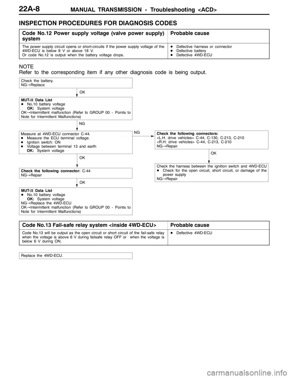
INSPECTION PROCEDURES FOR DIAGNOSIS CODES
Code No.12 Power supply voltage (valve power supply)
systemProbable cause
The power supply circuit opens or short-circuits if the power supply voltage of the
4WD-ECU is below 9 V or above 18 V.
Or code No.12 is output when the battery voltage drops.DDefective harness or connector
DDefective battery
DDefective 4WD-ECU
NOTE
Refer to the corresponding item if any other diagnosis code is being output.
OKOK
NG
NG
OK
Check the battery.
NG→Replace
Measure at 4WD-ECU connector C-44.
DMeasure the ECU terminal voltage.
DIgnition switch: ON
DVoltage between terminal 13 and earth
OK:System voltageCheck the following connectors:
C-44, C-130, C-213, C-210
C-44, C-213, C-210
NG→Repair
MUT-IIData List
DNo.10 battery voltage
OK:System voltage
OK→Intermittent malfunction (Refer to GROUP 00 - Points to
Note for Intermittent Malfunctions)
OK
Check the following connector:C-44
NG→Repair
MUT-IIData List
DNo.10 battery voltage
OK:System voltage
NG→Replace the 4WD-ECU
OK→Intermittent malfunction (Refer to GROUP 00 - Points to
Note for Intermittent Malfunctions)
Check the harness between the ignition switch and 4WD-ECU
DCheck for the open circuit, short circuit, or damage of the
power supply
NG→Repair
Code No.13 Fail-safe relay system Probable cause
Code No.13 will be output as the open circuit or short circuit of the fail-safe relay
when the voltage is above 6 V during failsafe relay OFF or when the voltage is
below 6 V during ON.DDefective 4WD-ECU
Replace the 4WD-ECU.