Page 663 of 1449
MPI -On-vehicle Service13A-131
COMPONENT LOCATION
NameSymbolNameSymbol
A/C relayJFuel pump relay 1, 2Q
A/C switchTFuel pump relay 3H
Air flow sensor (integrated intake air tempera-
ture sensor and barometric pressure sensor)OFuel pump resistorH
Camshaft position sensorNIdle speed control servo (stepper motor)G
Crank angle sensorKIgnition coil (integrated power transister)M
Detonation sensorEInjectorC
Diagnosis connectorSOxygen sensor (front)L
EGR control solenoid valveDOxygen sensor (rear)X
Engine control relayIPower steering fluid pressure switchA
Engine coolant temperature sensorNResistor (for injector)H
Engine warning lamp (check engine lamp)RSecondary air control solenoid valveD
Engine-ECUUThrottle position sensorG
Fan motor relayJVehicle speed sensorF
Fuel pressure control solenoid valveBWaste gate solenoid valveP
ABCDEFGHIJK
LMNOP
QRSTU
Page 664 of 1449

MPI -On-vehicle Service13A-132
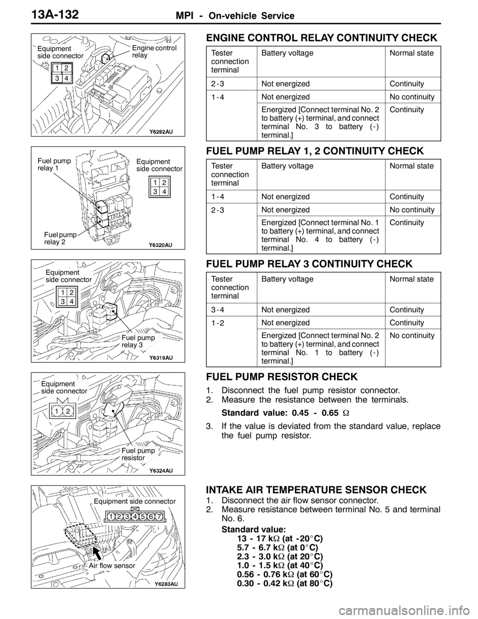
ENGINE CONTROL RELAY CONTINUITY CHECK
Tester
connection
terminalBattery voltageNormal state
2-3Not energizedContinuity
1-4Not energizedNo continuity
Energized [Connect terminal No. 2
to battery (+) terminal, and connect
terminal No. 3 to battery ( - )
terminal.]Continuity
FUEL PUMP RELAY 1, 2 CONTINUITY CHECK
Tester
connection
terminalBattery voltageNormal state
1-4Not energizedContinuity
2-3Not energizedNo continuity
Energized [Connect terminal No. 1
to battery (+) terminal, and connect
terminal No. 4 to battery ( - )
terminal.]Continuity
FUEL PUMP RELAY 3 CONTINUITY CHECK
Tester
connection
terminalBattery voltageNormal state
3-4Not energizedContinuity
1-2Not energizedContinuity
Energized [Connect terminal No. 2
to battery (+) terminal, and connect
terminal No. 1 to battery ( - )
terminal.]No continuity
FUEL PUMP RESISTOR CHECK
1. Disconnect the fuel pump resistor connector.
2. Measure the resistance between the terminals.
Standard value: 0.45 - 0.65Ω
3. If the value is deviated from the standard value, replace
the fuel pump resistor.
INTAKE AIR TEMPERATURE SENSOR CHECK
1. Disconnect the air flow sensor connector.
2. Measure resistance between terminal No. 5 and terminal
No. 6.
Standard value:
13 - 17 kΩ(at - 20_C)
5.7 - 6.7 kΩ(at 0_C)
2.3 - 3.0 kΩ(at 20_C)
1.0 - 1.5 kΩ(at 40_C)
0.56 - 0.76 kΩ(at 60_C)
0.30 - 0.42 kΩ(at 80_C)
Equipment
side connectorEngine control
relay
1
32
4
Equipment
side connector Fuel pump
relay 1
Fuel pump
relay 21
32
4
Equipment
side connector
Fuel pump
relay 3 1
32
4
Equipment
side connector
Fuel pump
resistor 12
Air flow sensor
Equipment side connector
123456 7
Page 670 of 1449

MPI -On-vehicle Service13A-138
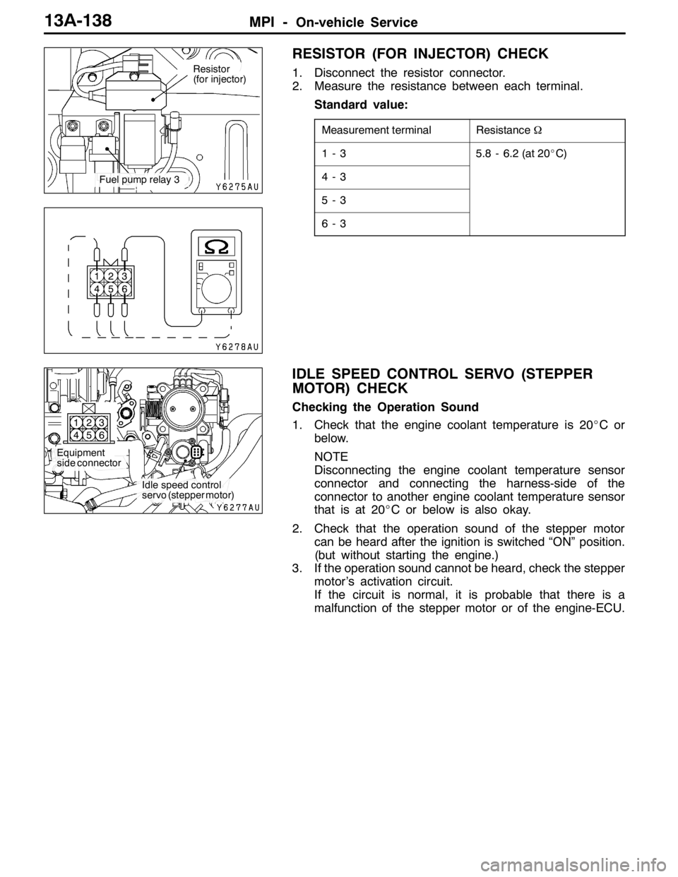
RESISTOR (FOR INJECTOR) CHECK
1. Disconnect the resistor connector.
2. Measure the resistance between each terminal.
Standard value:
Measurement terminalResistanceΩ
1-35.8 - 6.2 (at 20_C)
4-3
5-3
6-3
IDLE SPEED CONTROL SERVO (STEPPER
MOTOR) CHECK
Checking the Operation Sound
1. Check that the engine coolant temperature is 20_Cor
below.
NOTE
Disconnecting the engine coolant temperature sensor
connector and connecting the harness-side of the
connector to another engine coolant temperature sensor
that is at 20_C or below is also okay.
2. Check that the operation sound of the stepper motor
can be heard after the ignition is switched “ON” position.
(but without starting the engine.)
3. If the operation sound cannot be heard, check the stepper
motor’s activation circuit.
If the circuit is normal, it is probable that there is a
malfunction of the stepper motor or of the engine-ECU.
Resistor
(for injector)
Fuel pump relay 3
1
42
53
6
Equipment
side connector
Idle speed control
servo (stepper motor) 1
42
53
6
Page 678 of 1449
MPI -Engine Control Resistor, Relay13A-146
ENGINE CONTROL RESISTOR, RELAY
REMOVAL AND INSTALLATION
Pre-removal and Post-installation Operation
DStrut Tower Bar Removal and Installation (Refer to GROUP 42.)
DHarness Connector Connection
213
4
5.0�¶1.0 N·m
5.0±1.0N·m5.0±1.0N·m
2.5±0.5N·m
5.0±1.0N·m
AYC relay
4 2
5.0±1.0N·m
5.0±1.0N·mAYC relay5.0±1.0N·m5.0±1.0N·m
2.5±0.5N·m13
Removal steps
DAYC relay
1. Fuel pump relay
2. Injector resistor
3. Bracket
4. Fuel pump resistor
Page 689 of 1449
14-1
ENGINE COOLING
CONTENTS
GENERAL INFORMATION 2..................
SERVICE SPECIFICATIONS 2.................
LUBRICANT 2...............................
SEALANT 2..................................
SPECIAL TOOLS 3...........................
TROUBLESHOOTING 3.......................
ON-VEHICLE SERVICE 6.....................
Engine Coolant Leak Checking 6................
Radiator Cap Opening Pressure Check 6........Engine Coolant Replacement 6..................
Concentration Measurement 7...................
Radiator Fan Relay Continuity Check 8..........
Radiator Fan Controller Check 8................
Radiator Fan Motor Check 10...................
THERMOSTAT 11............................
WATER PUMP 13............................
WATER HOSE AND WATER PIPE 14..........
RADIATOR 15................................
Page 691 of 1449

ENGINE COOLING -Special Tools/Troubleshooting14-3
SPECIAL TOOLS
ToolNumberNameUse
A
B
C
DMB991223
A: MB991219
B: MB991220
C: MB991221
D: MB991222Harness set
A: Test harness
B: LED harness
C: LED harness
adapter
D: ProbeDMeasurement of terminal voltage
DInspection of radiator fan controller
A: Connector pin contact pressure
inspection
B: Power circuit inspection
C: Power circuit inspection
D: Commercial tester connection
MB991658Test harnessInspection of radiator fan controller
APS
MB991791Throttle cotrollerInspection of radiator fan controller
[Use the accelerator pedal position sensor
disconnected from harness.]
TROUBLESHOOTING
INSPECTION CHART FOR TROUBLE SYMPTOMS
Trouble symptomsInspection procedure
No.Reference page
Radiator fan does not operate.114-3
Radiator fan does not change speed or stop.214-5
INSPECTION PROCEDURE FOR TROUBLE SYMPTOMS
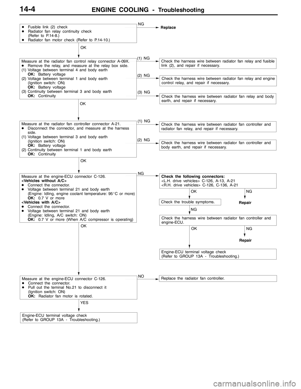
Inspection Procedure 1
Radiator fan does not operate.
Probable cause
Failure may occur on the power supply of the radiator fan controller and the
earth circuit.
Failure may also occur on the radiator fan controller and engine-ECU.DMalfunction of fusible link
DMalfunction of radiator fan relay
DMalfunction of radiator fan controller
DMalfunction of radiator fan motor
DMalfunction of engine-ECU
DMalfunction of harness, connector
Page 692 of 1449

ENGINE COOLING -Troubleshooting14-4
Measure at the engine-ECU connector C-126.
DConnect the connector.
DPull out the teminal No.21 to disconnect it
(Ignition switch: ON)
OK:Radiator fan motor is rotated.
YES
Engine-ECU terminal voltage check
(Refer to GROUP 13A - Troubleshooting.)NO
Replace the radiator fan controller.
NG
Repair
OK
NG
Repair
OK
Check the harness wire between radiator fan controller and
engine-ECU.
Measure at the engine-ECU connector C-126.
DConnect the connector.
DVoltage between terminal 21 and body earth
(Engine: Idling, engine coolant temperature: 95_C or more)
OK:0.7 V or more
DConnect the connector.
DVoltage between terminal 21 and body earth
(Engine: Idling, A/C switch: ON)
OK:0.7 V or more (When A/C compressor is operating)NG
(2) NGCheck the harness wire between radiator fan controller and
body earth, and repair if necessary.
OK
Measure at the radiator fan controller connector A-21.
DDisconnect the connector, and measure at the harness
side.
(1) Voltage between terminal 3 and body earth
(Ignition switch: ON)
OK:Battery voltage
(2) Continuity between terminal 1 and body earth
OK:Continuity(1) NGCheck the harness wire between radiator fan controller and
radiator fan relay, and repair if necessary.
(3) NGCheck the harness wire between radiator fan relay and body
earth, and repair if necessary.
(2) NGCheck the harness wire between radiator fan relay and engine
control relay, and repair if necessary.
OK
Measure at the radiator fan control relay connector A-09X.
DRemove the relay, and measure at the relay box side.
(1) Voltage between terminal 4 and body earth
OK:Battery voltage
(2) Voltage between terminal 1 and body earth
(Ignition switch: ON)
OK:Battery voltage
(3) Continuity between terminal 3 and body earth
OK:Continuity(1) NGCheck the harness wire between radiator fan relay and fusible
link (2), and repair if necessary.
DFusible link (2) check
DRadiator fan relay continuity check
(Refer to P.14-8.)
DRadiator fan motor check (Refer to P.14-10.)NG
Replace
OK
OK
Engine-ECU terminal voltage check
(Refer to GROUP 13A - Troubleshooting.)
Check the following connectors:
C-126, A-13, A-21
C-126, C-136, A-21
NG
Check the trouble symptoms.
Page 693 of 1449

ENGINE COOLING -Troubleshooting14-5
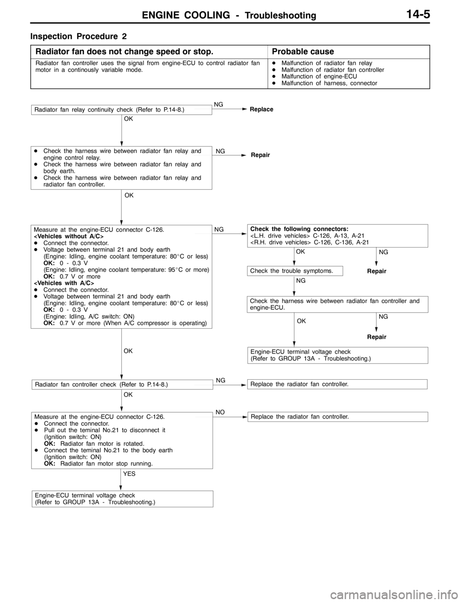
Inspection Procedure 2
Radiator fan does not change speed or stop.
Probable cause
Radiator fan controller uses the signal from engine-ECU to control radiator fan
motor in a continously variable mode.DMalfunction of radiator fan relay
DMalfunction of radiator fan controller
DMalfunction of engine-ECU
DMalfunction of harness, connector
Measure at the engine-ECU connector C-126.
DConnect the connector.
DPull out the teminal No.21 to disconnect it
(Ignition switch: ON)
OK:Radiator fan motor is rotated.
DConnect the teminal No.21 to the body earth
(Ignition switch: ON)
OK:Radiator fan motor stop running.
YES
Engine-ECU terminal voltage check
(Refer to GROUP 13A - Troubleshooting.)NO
Replace the radiator fan controller.
OK
Radiator fan controller check (Refer to P.14-8.)NGReplace the radiator fan controller.
OK
Measure at the engine-ECU connector C-126.
DConnect the connector.
DVoltage between terminal 21 and body earth
(Engine: Idling, engine coolant temperature: 80_C or less)
OK:0 - 0.3 V
(Engine: Idling, engine coolant temperature: 95_C or more)
OK:0.7 V or more
DConnect the connector.
DVoltage between terminal 21 and body earth
(Engine: Idling, engine coolant temperature: 80_C or less)
OK:0 - 0.3 V
(Engine: Idling, A/C switch: ON)
OK:0.7 V or more (When A/C compressor is operating)NG
OK
DCheck the harness wire between radiator fan relay and
engine control relay.
DCheck the harness wire between radiator fan relay and
body earth.
DCheck the harness wire between radiator fan relay and
radiator fan controller.NG
Repair
NG
Replace
OK
OK
OK
Check the following connectors:
C-126, A-13, A-21
C-126, C-136, A-21
NG
Engine-ECU terminal voltage check
(Refer to GROUP 13A - Troubleshooting.)
Check the trouble symptoms.
NG
NG
Repair
Repair
Radiator fan relay continuity check (Refer to P.14-8.)
Check the harness wire between radiator fan controller and
engine-ECU.