2007 MITSUBISHI LANCER EVOLUTION relay
[x] Cancel search: relayPage 630 of 1449

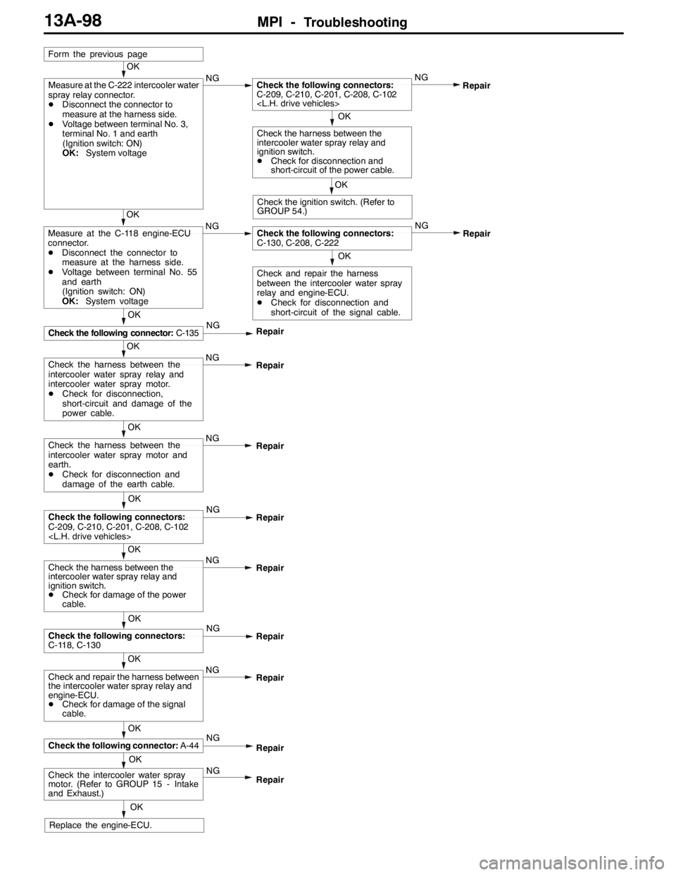
MPI -Troubleshooting13A-98
OK
NG
OK
Check the harness between the
intercooler water spray relay and
ignition switch.
DCheck for damage of the power
cable.Repair
OK
OK
Check the following connector:C-135NG
Repair
NG
NG
OK
Measure at the C-118 engine-ECU
connector.
DDisconnect the connector to
measure at the harness side.
DVoltage between terminal No. 55
and earth
(Ignition switch: ON)
OK:System voltageOKCheck the following connectors:
C-130, C-208, C-222NG
NG
OK
Measure at the C-222 intercooler water
spray relay connector.
DDisconnect the connector to
measure at the harness side.
DVoltage between terminal No. 3,
terminal No. 1 and earth
(Ignition switch: ON)
OK:System voltage
Form the previous page
OKRepair
Check the harness between the
intercooler water spray relay and
intercooler water spray motor.
DCheck for disconnection,
short-circuit and damage of the
power cable.
Check the following connectors:
C-209, C-210, C-201, C-208, C-102
Repair
Replace the engine-ECU.
OK
Check the following connectors:
C-209, C-210, C-201, C-208, C-102
Repair
OK
Check and repair the harness
between the intercooler water spray
relay and engine-ECU.
DCheck for disconnection and
short-circuit of the signal cable.
OK
Check the ignition switch. (Refer to
GROUP 54.)
Check the harness between the
intercooler water spray relay and
ignition switch.
DCheck for disconnection and
short-circuit of the power cable.
Repair
NG
OK
Check the harness between the
intercooler water spray motor and
earth.
DCheck for disconnection and
damage of the earth cable.Repair
OK
Check the following connectors:
C-118, C-130NG
Repair
NG
OK
Check and repair the harness between
the intercooler water spray relay and
engine-ECU.
DCheck for damage of the signal
cable.Repair
OK
Check the following connector:A-44NG
Repair
OK
Check the intercooler water spray
motor. (Refer to GROUP 15 - Intake
and Exhaust.)Repair NG
Page 632 of 1449

MPI -Troubleshooting13A-100
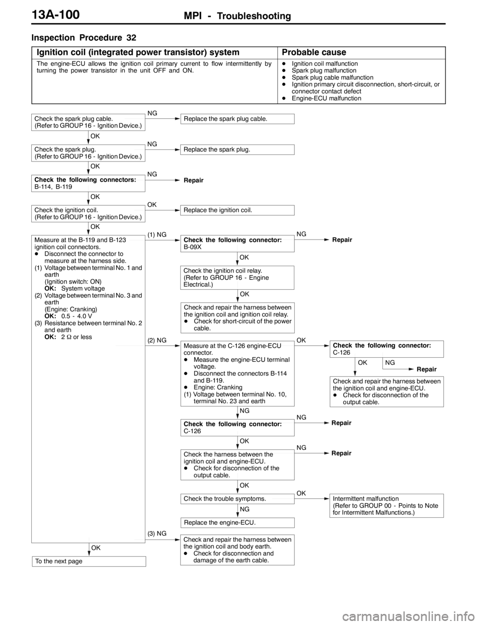
Inspection Procedure 32
Ignition coil (integrated power transistor) system
Probable cause
The engine-ECU allows the ignition coil primary current to flow intermittently by
turning the power transistor in the unit OFF and ON.DIgnition coil malfunction
DSpark plug malfunction
DSpark plug cable malfunction
DIgnition primary circuit disconnection, short-circuit, or
connector contact defect
DEngine-ECU malfunction
OK
Check and repair the harness between
the ignition coil and engine-ECU.
DCheck for disconnection of the
output cable.
OK
To the next page
(3) NGCheck and repair the harness between
the ignition coil and body earth.
DCheck for disconnection and
damage of the earth cable.
NG
Replace the engine-ECU.
OK
Check the trouble symptoms.OKIntermittent malfunction
(Refer to GROUP 00 - Points to Note
for Intermittent Malfunctions.) NG
OK
Check the harness between the
ignition coil and engine-ECU.
DCheck for disconnection of the
output cable.Repair NG
NG
Check the following connector:
C-126Repair
(2) NGMeasure at the C-126 engine-ECU
connector.
DMeasure the engine-ECU terminal
voltage.
DDisconnect the connectors B-114
and B-119.
DEngine: Cranking
(1) Voltage between terminal No. 10,
terminal No. 23 and earthOKCheck the following connector:
C-126
OK
Check and repair the harness between
the ignition coil and ignition coil relay.
DCheck for short-circuit of the power
cable.
OK
Check the ignition coil relay.
(Refer to GROUP 16 - Engine
Electrical.)
OK
Measure at the B-119 and B-123
ignition coil connectors.
DDisconnect the connector to
measure at the harness side.
(1) Voltage between terminal No. 1 and
earth
(Ignition switch: ON)
OK:System voltage
(2) Voltage between terminal No. 3 and
earth
(Engine: Cranking)
OK:0.5 - 4.0 V
(3) Resistance between terminal No. 2
and earth
OK:2Ωor less(1) NGCheck the following connector:
B-09XNG
Repair
OK
Check the ignition coil.
(Refer to GROUP 16 - Ignition Device.)OKReplace the ignition coil.
OK
Check the following connectors:
B-114, B-119NG
Repair
OK
Check the spark plug.
(Refer to GROUP 16 - Ignition Device.)NGReplace the spark plug.
Check the spark plug cable.
(Refer to GROUP 16 - Ignition Device.)NGReplace the spark plug cable.
NG
Repair
Page 633 of 1449

MPI -Troubleshooting13A-101
NG
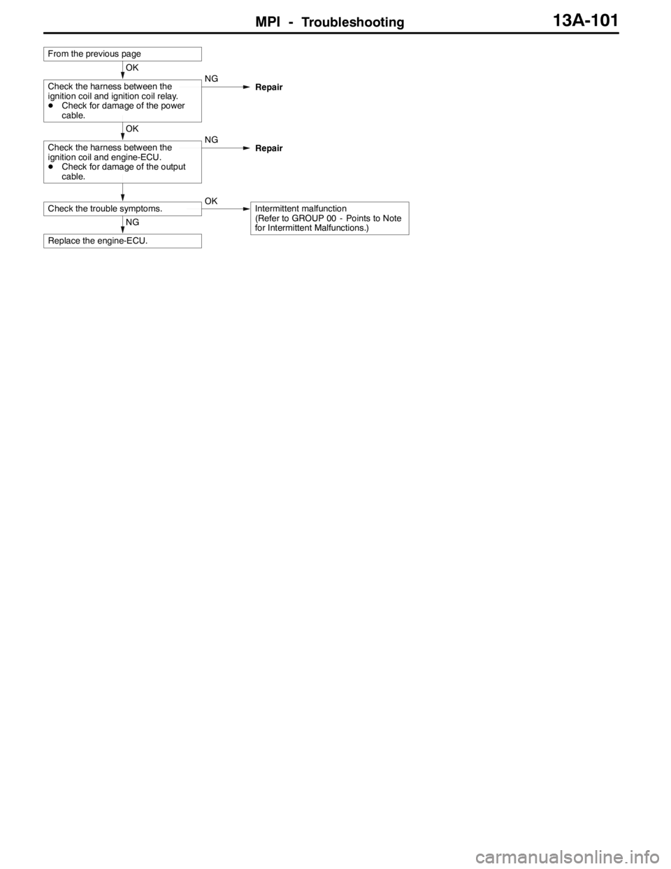
Replace the engine-ECU.
Check the trouble symptoms.OKIntermittent malfunction
(Refer to GROUP 00 - Points to Note
for Intermittent Malfunctions.)
OK
Check the harness between the
ignition coil and engine-ECU.
DCheck for damage of the output
cable.NG
Repair
OK
Check the harness between the
ignition coil and ignition coil relay.
DCheck for damage of the power
cable.NG
Repair
From the previous page
Page 637 of 1449

MPI -Troubleshooting13A-105
Item
No.Reference
page Inspection
procedure
No. Normal condition Inspection contents Inspection
item
44Ignition ad-
vanceDEngine: After
having warmed
up
DTiming lamp is
set(Thetiming
Engine: Idle operation0-13_BTDC--
set.(Thetiming
lamp is set in
order to check
actual ignition
timing.)
2,500 r/min20 - 40_BTDC
45Idle speed
control
(stepper)
motor
position*
3
DEngine coolant
temperature:
80 - 90_C
DLamps, electric
cooling fan and
all accessories:
OFF
DTransmission:
A/C switch: OFF2 - 25 STEP--
DTransmission:
Neutral
DEngine: Idle
operation
DWhen A/C switch
is ON, A/C
compressor
should be operat-
ing
A/C switch: OFF→ONIncreases by 10 -
70 steps
49A/C relayEngine: After having
warmed up/Engine is
idlingA/C switch: OFFOFF (Compressor
clutch is not oper-
ating)Procedure
No. 2713A-92
A/C switch: ONON (Compressor
clutch is operat-
ing)
59Oxygen
sensor
(rear)Engine: After having
warmed-upWhen engine is sud-
denly raced0 and 600 - 1,000
mV alternate.Code No.
P013613A-27
81LLearned
valueEngine: After having warmed up, running with no
load at 2,500 r/min. (During air/fuel ratio
feedback control)- 12.5 - 12.5%--
82LFeedbackEngine: After having warmed up, running with no
load at 2,500 r/min. (During air/fuel ratio
feedback control)- 20 - 20%--
87LEngine
load
Engine: After having
warmedup
Idle operation15 - 35%--
loadwarmedup
2,500 r/min15 - 35%--
Page 639 of 1449

MPI -Troubleshooting13A-107
ACTUATOR TEST REFERENCE TABLE
Item
No.Inspection
itemDrive contentsInspection contentsNormal conditionInspection
procedure
No.Reference
page
01InjectorsCut fuel to No.
1 injectorEngine: After having warmed
up/Engine is idling
(C tthfllth
Idling condition
becomes different
(becomesunsta
Code No.
P020113A-30
02Cut fuel to No.
2 injector(Cut the fuel supply to each
injector in turn and check
cylinders which don’t affect
idli )
(becomes unsta-
ble).Code No.
P020213A-31
03Cut fuel to No.
3 injector
y
idling.)Code No.
P020313A-32
04Cut fuel to No.
4 injectorCode No.
P020413A-33
07Fuel pumpFuel pump
operates and
fuel is recircu-
lated.DEngine:
Cranking
DFuel
pump:
Forced
driving
Inspect
according
Pinch the
return hose
with fingers
to feel the
pulse of the
fuel being
recirculated.Pulse is felt.Procedure
No. 2313A-85
according
to both
the above
conditions.
Listen near
the fuel tank
for the
sound of
fuel pump
operation.Sound of opera-
tion is heard.
08Purge
control
solenoid
valveSolenoid valve
turns from
OFF to ON.Ignition switch: “ON”Sound of opera-
tion can be heard
when solenoid
valve is driven.Code No.
P044313A-41
09Fuel
pressure
control
solenoid
valveSolenoid valve
turns from
OFF to ON.Ignition switch: “ON”Sound of opera-
tion can be heard
when solenoid
valve is driven.Code No.
P110513A-48
10EGR con-
trol sole-
noid valveSolenoid valve
turns from
OFF to ON.Ignition switch: “ON”Sound of opera-
tion can be heard
when solenoid
valve is driven.Code No.
P040313A-39
12Waste
gate sole-
noid valveSolenoid valve
turns from
OFF to ON.Ignition switch: “ON”Sound of opera-
tion can be heard
when solenoid
valve is driven.Code No.
P110413A-47
13Fuel pump
relay 3Fuel pump
relay 3 turns
from OFF to
ON.DIgnition switch: “ON”
DListen near the fuel tank
for the sound of fuel pump
operation.Sound of opera-
tion is heard.Procedure
No. 2313A-85
17Basic igni-
tion timingSet to ignition
timing
adjustment
modeEngine: Idling
Timing light is set5_BTDC--
Page 641 of 1449

MPI -TroubleshootingMPI -Troubleshooting13A-109
Engine-ECU Connector Terminal Arrangement
Terminal No.Check itemCheck condition (Engine condition)Normal condition
1No. 1 injectorWhile engine is idling after having warmed up,
suddenlydepresstheacceleratorpedal
From 11 - 14 V, momentarily
dropsslightly
14No. 2 injector
suddenlydepressthe accelerator pedal.drops slightly
2No. 3 injector
15No. 4 injector
3Fuel pressure control
solenoidvalve
Ignition switch: “ON”System voltage
solenoidvalve
Engine: Cranking→Idle operation
(within approximately 2 minutes or less)1 V or less→System voltage
4Stepper motor coil
startedSystem voltage↔0-6V
(Changes repeatedly)
17Stepper motor coil
5Stepper motor coil
18Stepper motor coil
6EGR control solenoid
valve
Ignition switch: “ON”System Voltage
valve
While engine is idling, suddenly depress the
accelerator pedal.From system voltage,
momentarily drops
8A/C relayDEngine: Idle operation
DA/Cswitch:OFF→ON(A/Ccompressor
System voltage or momen-
tarily6Vormore→1VorDA/Cswitch:OFF→ON(A/Ccompressor
runs)tarily6Vor more→1Vor
less
9Purge control sole-
noidvalve
Ignition switch: “ON”System voltage
noidvalve
Engine: Idle operation1 V or less
10Ignition coil - No.1,
No.4Engine speed: 3,000 r/min0.3 - 3.0 V
23Ignition coil - No.2,
No.3
11Waste gate solenoid
valve
Ignition switch: “ON”System voltage
valve
Engine: After warm-up, idle operation
(When using premium gasoline)1 V or less
Page 642 of 1449

MPI -Troubleshooting13A-110
Terminal No.Normal condition Check condition (Engine condition) Check item
12Power supplyIgnition switch: “ON”System voltage
25
19Air flow sensor reset
signal
Engine: Idle operation0-1V
signal
Engine speed: 3,000 r/min6-9V
21Fan controllerRadiator fan is not operating0 - 0.3 V
Radiator fan is operating0.7 V or more
22Fuel pump relay 2Ignition switch: “ON”System voltage
Engine: Idle operation1 V or less
24A/C load signalDEngine:
Idle operation
DA/C switch: ON
(A/C compressor
runs)DOutdoor air
sensor ambient
temperature:
18_C or more
DA/C setting
temperature:
Minimum
temperature
DA/C air volume:
Maximum1 V or less
DA/C setting
temperature:
indoor
temperature
DA/C air volume:
MinimumSystem voltage
32Condenser fan motor
relay (HI)Fan inactive state
(Engine coolant temperature: 90_C or less)System voltage
Fan high-speed rotation state
(Engine coolant temperature: 105_C or more)1 V or less
33Alternator G terminalDEngine: After warm-up, idle operation
DRadiator fan: Not operating
DHeadlamp: OFF→ON
DStop lamp: OFF→ON
DRear defogger switch: OFF→ONVoltage increases by
0.2 - 3.5 V
34Condenser fan motor
relay (LOW)Fan inactive state
(Engine coolant temperature: 90_C or less)System voltage
Fan low-speed rotation state (Engine coolant
temperature: 95 - 100_C or more)1 V or less
35Intercooler water
spraylamp
Ignition switch: “ON”System voltage
spraylamp
Ignition switch: “LOCK” (OFF)1 V or less
36Engine warning lampIgnition switch: “LOCK” (OFF)→“ON”1 V or less→System
voltage (After several se-
conds have elapsed)
Page 643 of 1449

MPI -Troubleshooting13A-111
Terminal No.Normal condition Check condition (Engine condition) Check item
37Power steering fluid
pressure switchEngine: Idling after
warming upWhen steering wheel
is stationarySystem voltage
When steering wheel
is turned1 V or less
38Engine control relayIgnition switch: “LOCK” (OFF)System voltage
Ignition switch: “ON”1 V or less
39Fuel pump relay 3While engine is idling, suddenly depress the
accelerator pedal.Temporarily rises slightly
from 1 V or less.
41Alternator FR
terminalDEngine: After warm-up, idle operation
DRadiator fan: Not operating
DHead lamp: OFF→ON
DStop lamp: OFF→ON
DRear deffogger switch: OFF→ONVoltage decrease
44Intercooler water
spray switch (Auto)DIgnition switch: “ON”
DIntercooler water spray switch: ON1 V or less
DIgnition switch: “ON”
DIntercooler water spray switch: OFFSystem voltage
45A/C switchEngine: Idle operationTurn the A/C switch
OFF0.5 V or less
DA/C switch: ON
DA/C setting
temperature
When room tem-
perature is 25_C
or more: Max
Cool
When room tem-
perature is 25_C
or less: Max. HotSystem voltage
53Secondary air control
solenoid valveIgnition switch: “ON”System voltage
54Oxygen sensor
heater(Rear)
Engine: Idling after warming up1 V or less
heater(Rear)
Engine speed: 5,000r/minSystem voltage
55Intercooler water
sprayrelay
Ignition switch: “ON”System voltage
spray relay
Ignition switch: “LOCK” (OFF)1 V or less
58Tachometer signalEngine speed: 3,000r/min0.3 - 3.0 V
60Oxygen sensor
heater(front)
Engine: Idling after warming up1 V or less
heater(front)
Engine speed: 5,000r/minSystem voltage
71Ignition switch - STEngine: Cranking8 V or more